
Related Manuals for Sorel SBMC


Summary of Contents for Sorel SBMC
- Page 1 Biomass Controller SBMC Installation and operating instructions Read carefully before installation, commissioning and operation...
-
Page 2: Table Of Contents
Sensor Calibration Changes to the Unit Commissioning Warranty and Liability Factory Settings Disposal and Pollutants Heat quantity Flow rate supply flow (X) Description SBMC Offset ∆T Specifications Daylight saving time About the Controller Scope of supply 8. Menu Lock Hydraulic Variants 9. -
Page 3: Safety Instructions
Safety Instructions EU-Conformity By affixing the CE mark to the unit the manufacturer declares that the SBMC conforms to the following relevant safety regulations: EU low voltage directive 2014/35/EU EU electromagnetic compatibility directive 2014/30/EU conforms. Conformity has been verified and the corresponding documentation and the EU declaration of conformity are kept on file by the manufacturer. -
Page 4: Changes To The Unit
Changes to the Unit Changes, additions to or conversion of the unit are not permitted without written permission from the man- ufacturer. It is likewise forbidden to install additional components that have not been tested together with the unit. If it becomes clear that safe operation of the unit is no longer possible, for example because of damage to the housing, turn the Unit off immediately. -
Page 5: Description Sbmc
Description SBMC Specifications Model SBMC Biomass Controller Electrical specifications: Power supply 230 VAC +/- 10%, 50 ... 60 Hz Power consumption / standby 1,5 W - 2,0 W/ 1,5W Total switched power 460 VA for AC1 / 185 W for AC3... -
Page 6: About The Controller
About the Controller The Biomass Controller SBMC facilitates efficient use and function control of your System possible while its handling is intuitive. After every input step the suitable functions are matched to the keys and explained in a text above. In the menu 'measurement val- ues and settings' are help text and graphics in addition to key words. -
Page 7: Installation
Installation Electrical Terminals Mains voltages Low voltages 230 VAC 50 - 60 Hz max. 12 VAC / DC Terminal: Connection for: Terminal: Connection for: Network outer conductor L S1 (2x) Sensor 1 solid fuel boiler Network neutral conductor N S2 (2x) Sensor 2 storage Pump outer conductor L S3 (2x) -
Page 8: Wall Installation
Wall Installation 1. Unscrew cover screw completely. 2. Carefully pull upper part of housing from lower part. During the removal, the brackets are released as well. 3. Set upper part of housing aside Do not touch the electronics. 4. Hold the lower part of the housing up to the selected position and mark the three mounting holes. -
Page 9: Installing The Temperature Sensors
4. Install PE terminal block 5. Connect the supplied connection terminals see " Electrical Terminals " on page 7 and see " Hydraulic Variants " on page 6. When using fine-stranded cables with a screwdriver, press the orange handles. For single-wire cables or cables equipped with wire-end ferrules, simply insert the cable. -
Page 10: Operation
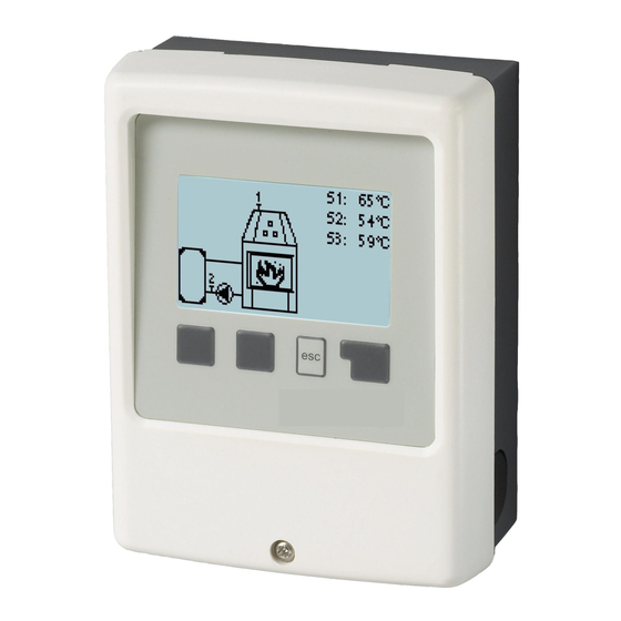
Operation Display and Input The display‘s (1), extensive text and graphical mode, enables simple, almost self-explanatory, operation of the con- troller. Entries are made using 4 keys (2+3), to which contextual functions are assigned. The ‚esc‘ key (3) is used to cancel an entry or to exit a menu. -
Page 11: Commissioning Help
Commissioning help 1. Set language and time 2. Commissioning help / setup wizard a) select or b) skip. The setup wizard guides through the necessary basic settings in the cor- rect order. Each parameter is explained in the control display. Pressing the „esc“ key takes you back to the previous setting. b) With free commissioning the settings should be made in the following order: menu 10. -
Page 12: Statistics
2. Statistics Serve for function control and long-term monitoring of the system. For system data statistics it is essential for the time to be set accurately on the controller. Please note that the clock con- tinues to run for about 24 hours if the mains voltage is inter- rupted, and afterward must be reset. -
Page 13: Eco Display Mode
Eco Display Mode In Eco Display Mode the backlight of the display is switched off if no buttons are pushed for 2 minutes. If a message exists, the backlight does not switch off until the message has been scanned by the user. 4. -
Page 14: Settings
5. Settings By no means does the controller replace the safety appliances on site! Tmin S1 Enable/start temperature at sensor 1: If this value on the sensor 1 (collector sensor) is exceeded and the other conditions are not fulfilled, the controller will turn on the affiliated pump or the valve. -
Page 15: Protective Functions
6. Protective Functions The 'Protective functions‘ can be used by specialists to activate and set vari- ous protective functions. By no means does the controller replace the safety appliances on site! Seizing Protection If the anti-seizing protection is activated, the controller switches the heat pump and the mixer on/off at 12:00 noon for 5 seconds to prevent seizing of the pump/valve after long periods of inactivity. -
Page 16: Special Functions
7. Special Functions Used to set basic items and expanded functions. The settings in this menu should only be changed by a specialist. Pump settings V1/ Signal V1 In this menu, the settings for the speed controlled output V1 are executed. Type of pump/ Type of signal The type of speed controlled pump used can be set here. -
Page 17: Setpoint
The specified percentages are variables, which may deviate more or less strongly depending on the system, pump and pump level. 100% is the maximum possible power of the controller. Setpoint This value is the control setpoint. If this value is below at the sensor, the speed is reduced. When it is exceeded, the speed is increased. -
Page 18: Offset ∆T
Offset ∆T Correction factor for the temperature difference for heat metering Since the collector temperature and the storage temperature can be used for the heat quantity metering, depending on the sys- tem, there may be deviations from the displayed collected temperature to the actual previous temperature or the displayed stor- age temperature to the actual return temperature. -
Page 19: Malfunctions/Maintenance
Malfunctions/Maintenance Replacing the Fuse Repairs and maintenance may only be performed by a specialist. Before working on the unit, switch off the power sup- ply and secure it against being switched on again! Check that there is no power flowing! Only use the supplied spare fuse or a fuse of the same design with the following specifications: 2 AT/250 VSOREL Art. - Page 20 Subject as a basic principle to errors and technical changes. Date and time of installation: Name of installation company: Space for notes: Your specialist dealer: Manufacturer: SOREL GmbH Mikroelektronik Reme-Str. 12 D - 58300 Wetter (Ruhr) +49 (0)2335 682 77 0 +49 (0)2335 682 77 10 info@sorel.de www.sorel.de...
Need help?
Do you have a question about the SBMC and is the answer not in the manual?
Questions and answers