Sorel CALEONbox Installation And Operating Instruction
Heating circuit controller for surface heating systems
Hide thumbs
Also See for CALEONbox:
- Installation and operating instruction (32 pages) ,
- System instruction (71 pages)

Related Manuals for Sorel CALEONbox


Summary of Contents for Sorel CALEONbox
- Page 1 °CALEONbox Heating circuit controller for surface heating systems Installation and operating instruction Read carefully before installation, commissioning and operation...
-
Page 2: Table Of Contents
CONTENT Safety Instructions EU-Conformity General Instructions Explanation of Symbols Changes to the Unit Warranty and Liability Disposal and Pollutants Description °CALEONbox Description Specifications Scope of supply Installation Wall Installation Electrical Connection Electrical Terminals Connection Examples Room Controller Connection Examples 1-Wire Sensors... -
Page 3: Safety Instructions
Safety Instructions EU-Conformity By affixing the CE mark to the unit the manufacturer declares that the°CALEONbox conforms to the following relevant safety reg- ulations: EU low voltage directive 2014/35/EU EU electromagnetic compatibility directive 2014/30/EU EU RoHS Directive 2011/65/EU EU WEEE Directive 2012/19/EU (Reg.nr. DE 23479719) conforms. -
Page 4: Changes To The Unit
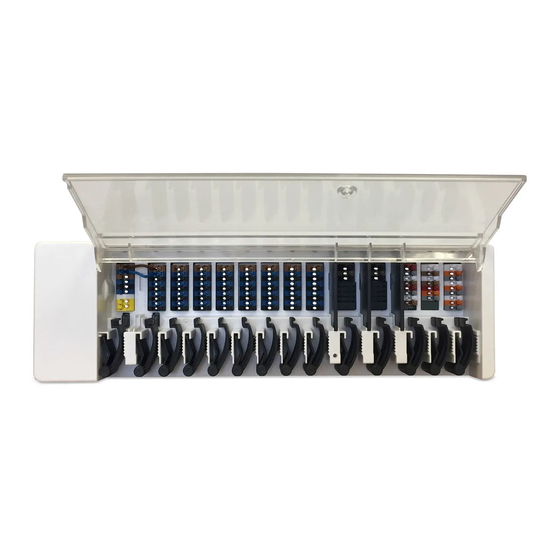
Description °CALEONbox Description The °CALEONbox is a universal heating and individual room controller for surface heating systems. In combination with up to 8 °CALEON Room Controllers, this enables efficient use and function control of your surface heating with intuitive operation. The inputs and outputs can be freely assigned via °CALEON or °CALEON Clima, so that different heating systems can be imple-... -
Page 5: Specifications
Specifications Model °CALEONbox Heating circuit controller for surface heating systems Temperature controller class (ErP) Energy efficiency (ErP) Standby loss 0,5 W Request type heater "On /off" and/or "modulating" Electrical specifications: Power supply 100-240VAC, 50 - 60 Hz Power consumption / standby... -
Page 6: Scope Of Supply
Wall Installation Fix the DIN rail horizontally to the wall using screws. Installation 1. Place the °CALEONbox on the upper edge of the DIN rail with the locking catch on top. 2 Engage the device by pressing it down. Ensure that the locking catches engage completely and that the device is firmly seated on the rail. -
Page 7: Electrical Terminals
The strain reliefs are suitable for flexible cables with a cable sheath diameter of 3 mm to 8 mm, primarily using the lower strain relief (as shown). Massive, thicker and thinner cables must be firmly laid and fixed on the installation side. -
Page 8: Connection Examples Room Controller
Connection Examples Room Controller Example 1: Tree Structure The first and last unit in the CAN-network in series must be fitted with terminating resistance. Example 2: Line The first and last unit in the CAN-network in series must be fitted with terminating resistance. -
Page 9: Connection Examples 1-Wire Sensors
Connection Examples 1-Wire Sensors Example 1: Tree structure - permitted total length 50 m A twisted pair cable must be used for the connecting cable. Example 2: Line - permitted total length 50 m The installation leads from one sensor to the next. A twisted pair cable must be used for the connecting cable. In parasitic operation (two wires), only the terminals GND and 1-Wire Data are used. -
Page 10: Operation
Operation To configure the °CALEONbox, you need at least one °CALEON Room Controller. This is connected to the °CALEONbox via the CAN bus as previously described (see " Electrical Connection " on page 6). Room Overview It displays room temperature, humidity and outdoor temperature. -
Page 11: Expert Menu
Expert Menu Overview > Operating Mode > Main Menu > Expert Language Selection Service values Set the device language. Overview of firmware and error mes- Time & Date sages. Setting of time and date and auto- Factory Settings matic summer/winter time The factory settings are restored in the changeover. -
Page 12: Devices
Signal setting for output N7. Signal N4 Signal setting for output N4. Overview > Operating mode > Main menu > Expert > Settings > Devices > °CALEONbox > Signal N1 Signal typ 0-10 / PWM Pump profile Setting of the signal type used... -
Page 13: Rooms
Rooms Overview > Operating mode > Main menu > Expert > Settings > Rooms Add Rooms °CALEON / Room 1 Adding rooms. Setting of location, sensors and actu- ators. Overview > Operating mode > Main menu > Expert > Settings > Rooms > °CALEON/ Room 1 Location Actuators Show the room in which the unit is... -
Page 14: Functions
Functions Overview > Operating mode > Main menu > Expert > Settings > Functions Thermostat 1 - 3 HC Mixer Activate and set the function. Activate and set the function. Heating Circuit Activate and set the function. Difference Activate and set the function. Timer 1 - 2 Activate and set the function. - Page 15 Overview > Operating mode > Main menu > Expert > Settings > Functions > Heating Circuit The heating circuit function starts the Flow heating pump at the defined output as Assignment of the heating circuit flow soon as at least one zone is active. sensor.
-
Page 16: Zones
Zones Overview > Operating mode > Main menu > Expert > Settings > Zones Zones Selection of the heating zone to be assigned or managed. Overview > Operating Mode > Main Menu > Expert > Settings > Zones > Zone B Output S/W Eco Assignment of the relay (output). -
Page 17: Example Zone Setting
Example Zone Setting Step 1 Select the relevant zone and assign an output (relay) to it. Step 2 Step 3 Step 4 Step 5 Select the room corresponding Set the mode in which the Set the desired outdoor switch- Set the desired outdoor switch- to the zone. -
Page 18: Service Values
Firmware CAN Status Displays the firmware version. Displays the CAN Status. Messages Status Displays the error memory. Displays the system status. Z-Wave Status CB Firmware Displays the Z-Wave status. Displays the °CALEONbox firmware version. WiFi Status Displays the WiFi status. -
Page 19: Set Operation Hours
Set Operation Hours Overview > Operating Mode > Main Menu > Timer Adjustment of individual heating times by a simple copy function for every day. Previous/Next week Selects the set day. Clock Time table of the selection in peri- ods of 30 minutes increments. Operating modes Menu Selects the operating mode to indi-... - Page 20 Subject as a basic principle to errors and technical changes. SOREL GmbH Mikroelektronik - Reme-Str. 12 - D - 58300 Wetter (Ruhr) - +49 (0)2335 682 77 0 - +49 (0)2335 682 77 10 - info@sorel.de - www.sorel.de...
Need help?
Do you have a question about the CALEONbox and is the answer not in the manual?
Questions and answers