Advertisement
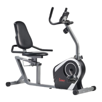
SMART MAGNETIC RESISTANCE RECUMBENT
BIKE WITH EASY ADJUSTABLE SEAT
SF-RB4616 SMART
USER MANUAL
IMPORTANT! Please retain owner's manual for maintenance and adjustment instructions. Your
satisfaction is very important to us, PLEASE DO NOT RETURN UNTIL YOU HAVE
CONTACTED US: support@sunnyhealthfitness.com or 1- 877 - 90SUNNY (877-907-8669).
Advertisement
Table of Contents

Subscribe to Our Youtube Channel
Related Manuals for Sunny SF-RB4616 SMART


Summary of Contents for Sunny SF-RB4616 SMART
- Page 1 SMART MAGNETIC RESISTANCE RECUMBENT BIKE WITH EASY ADJUSTABLE SEAT SF-RB4616 SMART USER MANUAL IMPORTANT! Please retain owner’s manual for maintenance and adjustment instructions. Your satisfaction is very important to us, PLEASE DO NOT RETURN UNTIL YOU HAVE CONTACTED US: support@sunnyhealthfitness.com or 1- 877 - 90SUNNY (877-907-8669).
-
Page 2: Important Safety Information
IMPORTANT SAFETY INFORMATION We thank you for choosing our product. To ensure your safety and health, please use this equipment correctly. It is important to read this entire manual before assembling and using the equipment. Safe and effective use can only be achieved if the equipment is assembled, maintained, and used properly. -
Page 3: Pre-Assembly Check List
PRE-ASSEMBLY CHECK LIST Before you start to assemble, please make sure all parts are included. SF-RB4616 SMART HARDWARE PACKAGE Step 5 Step 4 Step 1 #64 M8*25 2PCS # 5 5 1 6 * 8 * 1 . 5 4 P C S... -
Page 4: Hardware Package
HARDWARE PACKAGE SF-RB4616 SMART HARDWARE PACKAGE Step 5 Step 4 Step 1 #64 M8*25 2PCS # 5 5 1 6 * 8 * 1 . 5 4 P C S # 8 3 M 6 * 1 2 2 P C S Φ... - Page 5 ASSEMBLY INSTRUCTIONS We value your experience using Sunny Health and Fitness products. For assistance with parts or troubleshooting, please contact us at support@sunnyhealthfitness.com or 1-877-90SUNNY (877-907-8669). STEP 1: #66 S13-15-17 #58 M8*65 4PCS NOTE:The Front Stabilizer (No. 6F) is #54 φ20 *1.5 4PCS marked “FRONT”...
- Page 6 We value your experience using Sunny Health and Fitness products. For assistance with parts or troubleshooting, please contact us at support@sunnyhealthfitness.com or 1-877-90SUNNY (877-907-8669). STEP 3: #67 S6 Remove 4 Cross Head Screws (No. 51) #51 M5*10 4PCS from the back of the Computer (No. 24) using Allen Wrench (No.
- Page 7 We value your experience using Sunny Health and Fitness products. For assistance with parts or troubleshooting, please contact us at support@sunnyhealthfitness.com or 1-877-90SUNNY (877-907-8669). STEP 5: #68 S5 1 PC Attach the Slide Rail Assembly (No. #67 S6 1 PC 79) to the Main Frame (No.
- Page 8 MAINTENANCE & ADJUSTMENT GUIDE ADJUSTING THE SEAT To adjust the Seat Post (No. 4) forward or backward, while seated on the bike, put your feet on the floor. Shift down the Adjustable Handle (No. 76), then slide the seat to your desired position, lift the Adjustable Handle (No.
-
Page 9: Battery Installation And Replacement
BATTERY INSTALLATION AND REPLACEMENT Battery Battery Cover BATTERY INSTALLATION: 1. Take out 2 AAA batteries from computer box. 2. Press the buckle of battery cover on the back of the Computer (No. 24), then remove battery cover. -
Page 10: Exercise Computer
EXERCISE COMPUTER BLUETOOTH 1. The Bluetooth icon will flash when the meter is on or wakes from sleep mode. If no Bluetooth connection is established within 3 minutes, the Bluetooth icon will turn off. 2. The Bluetooth icon will stay on when it is connected. WIRELESS HEART RATE 1. - Page 11 FUNCTION SCAN: Display changes according to the next diagram every 6 seconds. and the icon will be flash TIME: The total working time with starting exercise. SPEED: The current speed with starting exercise. DISTANCE: The current distance with starting exercise. ...
-
Page 12: Troubleshooting
TROUBLESHOOTING PROBLEM SOLUTION 1. Remove the computer and verify that the wire from the computer is properly connected to the wire that comes from the front post. There is no display on the 2. Check if the batteries are correctly positioned and battery computer console. -
Page 13: Exploded Drawing
EXPLODED DRAWING ... -
Page 14: Parts List
PARTS LIST Description Spec. Description Spec. Main Frame Handle Grip Φ24*78 Front Post End Cap Φ25*1.5 Handle Pulse Front Handlebar 110*25 Sensor Seat Post End Cap 60*30*2.0 Rear Handlebar Grommet Φ15*12 Front Stabilizer Φ50*1.5*370 Tension Wire Rear Stabilizer Φ50*1.5*460 Spring Φ18*86.7 Idler Wheel Shaft Circlip... - Page 15 Description Spec. Description Spec. Allen Wrench Eccentric Wheel Φ25*38 Hexagon Socket Sensor Wire 1 L=350 M8*12 Fixing Bolt Hexagon Socket Sensor Wire 2 L=750 M6*12 Bolt Pulse Wire L=650 Flat Washer Φ16*Φ6.2*1.5 Outer Hexagon Hexagon Bolt M6*10 Foam Grip Φ23*3*430 Flat Washer Φ20*Φ8.3*2.0 Self-Tapping...
- Page 16 ...
Need help?
Do you have a question about the SF-RB4616 SMART and is the answer not in the manual?
Questions and answers