
Subscribe to Our Youtube Channel
Related Manuals for Sunny SF-RB4616


Summary of Contents for Sunny SF-RB4616
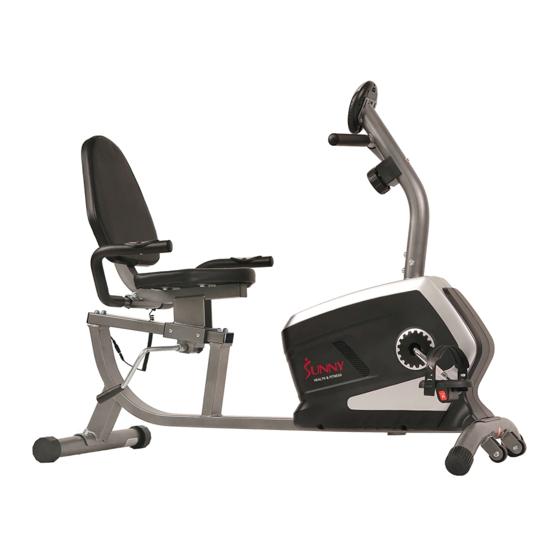
- Page 1 EASY ADJUSTABLE SEAT RECUMBENT BIKE SF-RB4616 USER MANUAL IMPORTANT: Please read this manual carefully before using the product. Retain owner’s manual future reference. Customer Service, please contact: support@sunnyhealthfitness.com...
-
Page 2: Important Safety Information
IMPORTANT SAFETY INFORMATION We thank you for choosing our product. To ensure your safety and health, please use this equipment correctly. It is important to read this entire manual before assembling and using the equipment. Safe and effective use can only be assured if the equipment is assembled, maintained, and used properly. -
Page 3: Exploded Drawing
EXPLODED DRAWING... -
Page 4: Hardware Package
HARDWARE PACKAGE... -
Page 5: Parts List
PARTS LIST Description Quantity External magnetic flywheels,200*72.5/3kg Main frame Bearing, 6000z Front post Tension spring, 18*48,Wire 2 Front Stabilizer Tap bolts, 9.8*4*M8*15,similar with BU3501 Cushion Frame Brake handle, 12*380 Handle bar Eccentric shaft,12*105 Adjusting tube Eccentric wheel,20*38 Magnetic board Powder metallurgy set,23*12.2*11 Idler link Lock washer, 30*2 Rear stabilizer... -
Page 6: Assembly Instructions
ASSEMBLY INSTRUCTIONS NOTICE A. Please make sure there has enough space around the machine before assembly. B. Ensure that you have the right tool. C. Check the parts and the hardware first. Span r tool Step1: Attach the Front Stabilizer (No. 3) to the Main Frame (No. 1) using 2 Bolts (No. 20). Tighten with Allen wrench. - Page 7 Step 2: Attach the Seat Cushion (No. 63) to the Cushion Frame (No. 4), making sure the correct side is facing up, using 2 Bolts (No. 28) and 2 Flat Washers (No. 23). Attach the Backrest Cushion (No. 64) to the Cushion Frame (No. 4) using 4 Bolts (No. 29) and 2 Flat Washers (No.
- Page 8 Step 4: Attach the Handle Bar (No. 5) to the Cushion Frame (No. 4) using Carriage Bolts (No. 25), Flat Washers (No. 23) and the Cap Nuts (No. 27). Step 5: Insert the Adjusting Tube (No. 6) into the Cushion Frame (No. 4) square tube holes and attach the Cushion Frame (No.
- Page 9 Step 6: Insert the Tension Control Wire (No. 72) to Tension Control Wire (No. 73) as shown, Then connect the Trunk Line (No. 78) with the Needle Sensor Line (No. 79) as shown and connect the Hand Pulse Wire 1 (No. 81) with the Hand Pulse Wire 2 (No. 82). Attach the Front post (No.
- Page 10 Step 8: Connect the Left & Right Pedal (No. 60L & R) onto the Left & Right Crank (No. 39). Left Pedal: Align the Left Pedal (No. 60) with the Left Crank Arm (No. 39) at 90 degrees and gently insert the pedal into the crank arm. Turn the pedal counter-clockwise as tightly as you can with your hand then secure with Spanner Tool.
- Page 11 ADJUSTING THE SADDLE Push the Brake Handle (No. 49) down to loosen (see Fig 1). Keep your feet on the pedals as leverage, then move the Cushion Frame (No. 4) to the desired position. Once positioned, pull up Brake Handle (No. 49) back to the vertical position to tighten (see Fig 2). Fig.
-
Page 12: Adjusting The Resistance
ADJUSTING THE RESISTANCE Adjust the resistance of the bike using the Tension Control (No. 72). Increase the level of resistance by turning the tension knob to the RIGHT (clockwise), decrease the level of resistance by turning the tension knob to the LEFT (counter-clockwise). ADJUSTING THE HEIGHT AND BALANCE In order to achieve a smooth and comfortable ride, you must ensure that the bike is stable. - Page 13 EXERCISE METER FUNCTIONAL BUTTONS MODE: Press this button to select functions. SET: Press to set the values of time, distance, calories, or pulse when not in scan mode. RESET: Press to reset time, distance and calories to zero when not in scan mode. FUNCTIONS Press “MODE”...
-
Page 14: Specifications
SPECIFICATIONS: AUTO SCAN Every 4 seconds 00:00’~99:59’ TIME CURRENT The maximum signal can be pickup is 99.9 SPEED MI/H FUNCTION TRIP DISTANCE 0.00~99.99 MI or 0.00~9999 MI CALORIES 0.1~999.9 KCAL 0.1~999.9 MI or 1 ~ 9999 MI PULSE RATE 40~206 BPM 2pcs of SIZE –AAA or UM –4 BATTERY TYPE OPERATING...
Need help?
Do you have a question about the SF-RB4616 and is the answer not in the manual?
Questions and answers
do I change batteries if the setting window is dark?