Table of Contents

Related Manuals for Sunny SF-RB4631


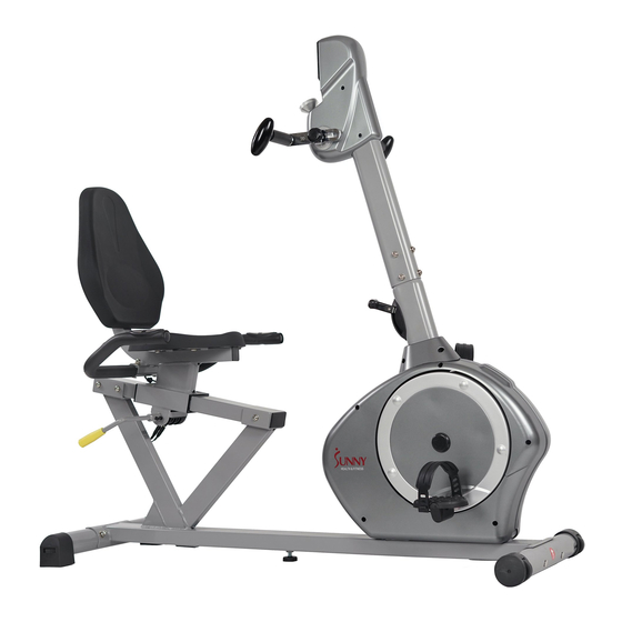
Summary of Contents for Sunny SF-RB4631
- Page 1 RECUMBENT BIKE WITH ARM EXERCISER SF-RB4631 USER MANUAL IMPORTANT! Read all instructions carefully before using this product. Retain owner’s manual for future reference. For customer service, please contact: support@sunnyhealthfitness.com...
-
Page 2: Important Safety Notice
IMPORTANT SAFETY NOTICE Note the following precaution before assembling and operating the machine. 1. Assemble the machine exactly as described in the instruction manual. 2. Check all the bolts, nuts and other connections before using the machine for the first time to ensure the machine is in the safe condition. - Page 3 EXPLODED DIAGRAM...
- Page 5 HARDWARE DRAWING & TOOLS Most of the listed assembly hardware have been packaged separately, but some hardware parts have been preassembled. In these instances, simply remove and reinstall the hardware as required.
- Page 6 PARTS LIST DESCRIPTION Q’TY DESCRIPTION Q’TY Main frame Wheeled end cap Seat tube Horseshoe-shaped end cap Handlebar 27L/R Pedal 1pr. Slide rail Adjustable pad Handlebar post Knob Front stabilizer Oval handle Rear stabilizer Foam grip Adjustment Handle Square plug 38*38*1.5 Square neck bolt Square plug 80*40*2 □...
-
Page 7: Main Frame (
ASSEMBLY INSTRUCTION STEP 1 1. Attach the Front Stabilizer (6) and the Rear Stabilizer (7) to the Main Frame (1) with the Square Neck Bolts (9), Arc Washers (12) and Ball Cap Nuts (11). 2. Attach the Adjustable Pad (28) to the Main Frame (1). STEP 2 Attach the Pedal (27L/R) to the Crank (40L/R) with the cross wrench. -
Page 8: Handlebar Post 1
STEP 3 Connect the Pulse Sensor Wire 2 (46) and Sensor Wire (43) with the wires of the Computer (44). Then attach the Handlebar Post (5) to the Main Frame (1) with the Hex Pan Head Screws (14), Arc Washers (13) and Washers (15). - Page 9 STEP 4 Attach the Rotating Handles (23L/R) to the Connecting Axle (45) with the Knob (29) and U Shape Board (24). Note: You can adjust the position of the Rotating Handles (23L/R) and Connecting Axle (45) by loosening the Knob (29), moving the Rotating Handles (23L/R) to desired position, and then tightening the Knob (29).
- Page 10 STEP 5 Attach the Slide Rail (4) to the Main Frame (1) with the Hex Pan Head Screws (14) and Washers (15) tightly.
-
Page 11: Adjustment Handle 1
STEP 6 1. Attach the Adjustment Handle (8) to the Axle (19), and secure tightly with the Hex Socket Cap Screws (22). Make sure the Adjustment Handle (8) is pointing up. 2. Set the Handlebar (3) onto the Seat Tube (2), and secure tightly with the Square Neck Bolts (10), Washers (15) and Ball Cap Nuts (11). - Page 12 STEP 7 1. Attach the Backrest (37) to the Seat Post (2) tightly with Hex Pan Head Screws (14) and Washers (15). 2. Attach the Saddle (36) to the Seat Post (2) tightly with Hex Pan Head Screws (14) and Washers (15).
-
Page 13: Knob
Adjusting the Tension To adjust the tension of the Rotating Handles (23L/R), turn the Tension Knob in front of the meter. Turn clockwise (+) to increase the tension, counterclockwise (-) to decrease the tension. To adjust the tension of the bike, move the Tension Switch B. 1 is the lowest tension. 8 is the highest tension. -
Page 14: Moving The Bike
Adjusting the Level If the bike is not level, adjust the End Caps (26). Moving the Bike Lift the bike by the Rear Stabilizer (7) until the wheels on the Front Stabilizer (6) touch the floor. Now you can move the bike. -
Page 15: Computer
EXERCISE COMPUTER INSTRUCTIONS MODE: Press to select function. Press and hold for 2 seconds to reset all values except TOTAL DIST FUNCTIONS AND OPERATIONS: 1. SCAN: Press MODE button until“▼ ”appears at SCAN Position. Computer will rotate through all the 6 functions: Time, Speed, Distance, Calorie, Total Distance, Pulse. Each function will display for 6 seconds.
Need help?
Do you have a question about the SF-RB4631 and is the answer not in the manual?
Questions and answers
how do you replace the batteries for the readout screen
To replace the batteries on the Sunny SF-RB4631 readout screen:
1. Use 2 AA batteries (included with the product).
2. If the display has a problem, replace both batteries at the same time.
3. Do not mix old and new batteries.
4. Do not mix different battery types.
5. Dispose of used batteries according to local and state guidelines.
This answer is automatically generated