Hyster H8.00-12.00XM Manual
Operators cab
Hide thumbs
Also See for H8.00-12.00XM:
- Service & repair manual (21 pages) ,
- Service & repair manual (21 pages)

Related Manuals for Hyster H8.00-12.00XM


Summary of Contents for Hyster H8.00-12.00XM
- Page 1 OPERATORS CAB H8.00-12.00XM (H170-280HD) [F007]; H13.00-16.00XM (H300-360HD) [E019]; H10.00-12.00XM-12EC (H360HD-EC) [E019] PART NO. 1494139 100 SRM 935...
-
Page 2: Table Of Contents
Heater and Air Conditioning Assembly......................Heater Parts, Replace............................ Heat Control Knob/Switches......................... Heat Control Knob/Cable ..........................Adjust ................................. Air Control Knob/Cable ..........................Adjust ................................. Air Filter, Replace............................Air Conditioning Condenser Fan(s), Standard .................... Remove............................... Install ................................. Air Conditioning Condenser Fan(s), Tropical ....................©2004 HYSTER COMPANY... - Page 3 Install ................................. Instruments, Switches, and Controls ....................... Switches ................................. Controls ................................Fuses and Relays ............................... Fuse Panel..............................Fuses ................................Relays ................................Label Replacement............................. Electrical Schematics............................This section is for the following models: H8.00-12.00XM (H170-280HD) [F007]; H13.00-16.00XM (H300-360HD) [E019]; H10.00-12.00XM-12EC (H360HD-EC) [E019]...
-
Page 4: General
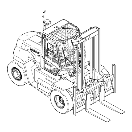
100 SRM 935 General General A fully-enclosed operator’s cab is positioned on four part of the operator’s cab. The cab is installed on a large rubber antivibration mounts to isolate opera- platform above main frame members. Step plates on tor from shock, noise, and vibration. See Figure 1. both sides of lift truck give access to cab. -
Page 5: Cab Repair
Cab Repair 100 SRM 935 Cab Repair REAR CAB ASSEMBLY NOTE: Interior covers are affixed with self-tapping screws. See Figure 2 for rear cab assembly. 1. COVER PLATE 6. HEADLINER 2. FUSE SECTION 7. REAR DUCT ASSEMBLY 3. RELAY SECTION 8. -
Page 6: Bottom Cab Assembly
100 SRM 935 Cab Repair BOTTOM CAB ASSEMBLY 4. Clear all obstacles from right-hand side (as seen from driver’s position) of truck. Provide mini- See Figure 3 for bottom cab assembly. mum of 2 m (7 ft) of clearance space. 5. -
Page 7: Lower Cab
Cab Repair 100 SRM 935 NOTE: If cab will not fully raise, lower cab until cab WARNING locks in partially open position, and fill tilt system Verify the lifting device has a minimum capac- with oil. See Oil Filling for Tilt System. ity to lift 1000 kg (2205 lb). -
Page 8: Install
100 SRM 935 Cab Repair 17. Connect a lift strap under overhead guard struc- 2. Verify that insulators are in place. See Figure 7. ture. Provide a cushion at top of door area to pre- vent damage. 18. Carefully lift cab away from lift truck. Set cab as- sembly in a suitable storage area and put blocks under cab to stabilize and prevent damage. -
Page 9: Oil Filling For Tilt System
Inching and Brake Pedals 100 SRM 935 Oil Filling for Tilt System CAUTION When oil has been added, put oil-absorbing ma- terial around filler plug before lowering cab. Excess oil may bleed out of relief valve, which is fitted in filler plug. 1. -
Page 10: Throttle Cable Adjustment
100 SRM 935 Throttle Cable Adjustment 1. BRAKE PEDAL 1. PEDAL ASSEMBLY AND FLOOR PLATES 2. INCHINGPEDAL 2. INCHING CABLE 3. ADJUSTMENT BOLT FOR BRAKE PEDAL 3. ADJUSTMENT CABLE COUPLING 4. ADJUSTMENT BOLT FOR INCHING/BRAKE 4. PEDAL END CABLE COUPLING PEDAL COUPLING 5. -
Page 11: Cable Alignment
Throttle Pedal Sensor 100 SRM 935 CABLE ALIGNMENT If increased throttle pedal effort is experienced over time, it may be due to alignment of the throttle cable. The throttle cable can be misaligned on: • Engine side • Pedal housing side In case of a misaligned cable, on either side, the ca- ble will show increased wear. -
Page 12: Seat Assembly Removal
100 SRM 935 Seat Assembly Removal Legend for Figure 14 1. DIMENSION A 2. THROTTLE PEDAL 3. THROTTLE PEDAL ADJUSTMENT 4. THROTTLE PEDAL SENSOR 5. MOUNTING SCREW 6. COUPLING 7. CABIN FLOOR PLATE 8. THROTTLE PEDAL STOP 9. COUNTERCLOCKWISE 10. SLOTTED HOLE Figure 14. -
Page 13: Power Assist Armrest
Steering Column Repair 100 SRM 935 Power Assist Armrest ADJUST 1. Disconnect cable from lever. See Figure 16. 2. Remove the mounting bolts that hold the gas spring assembly. 3. Loosen nut. 4. Adjust top section, clockwise or counterclock- wise, to obtain a free lever movement of 1.5 to 2.0 mm (0.06 to 0.079 in.). -
Page 14: Window Wipers Replacement
100 SRM 935 Window Wipers Replacement 5. Carefully mount steering pump with four steer- 6. Connect electrical connector. ing pump hex bolts to allow non-forced coupling 7. Connect battery ground lead. between steering pump and steering column. 8. Lower cab. See Lower Cab. 1. -
Page 15: Front Window Wiper Motor Assembly, Replace
Window Wipers Replacement 100 SRM 935 FRONT WINDOW WIPER MOTOR ASSEMBLY, REPLACE 1. Disconnect battery ground lead. 2. Disconnect connector. See Figure 20. 1. CONNECTOR 2. NUTS AND WASHERS Figure 21. Rear Wiper Motor Assembly TOP WINDOW WIPER MOTOR ASSEMBLY, REPLACE 1. -
Page 16: Window Washer Motors And Pumps
100 SRM 935 Window Replacement Window Washer Motors and Pumps WINDOW WIPER AND WASHER NOTE: Three window washer motors with pump as- semblies are attached to a water reservoir. See Fig- OPERATING SWITCHES ure 23. NOTE: The switch panel for the front, top, and rear NOTE: When replacing washer motor(s), verify that window wipers and washers is located on the side of water hose(s) is connected to proper pump(s). -
Page 17: Front Window, Replace
Window Replacement 100 SRM 935 1. FRONT WINDOW 1. FRONT WINDOW 3. TOP WINDOW 2. SEAL 2. REAR WINDOW 4. DOOR 3. CROSS SECTION SEAL ASSEMBLIES 4. STRING 5. PLASTIC THREAD (INSTALLATION TOOL) Figure 25. Doors/Glass Assemblies 6. CAB FRAME Figure 26. -
Page 18: Door Window, Replace
100 SRM 935 Window Replacement 11. Center the window and tighten bolts. NOTE: When replacement of window attachment is required, remove bottom screws, slide out window at- tachment, and replace. 1. RIGHT ANGLE BRACKETS 2. SCREWS 3. REAR BRACKET Figure 27. Top Window Brackets DOOR WINDOW, REPLACE 1. -
Page 19: Heater And Air Conditioning Assembly
Heater and Air Conditioning Assembly 100 SRM 935 Heater and Air Conditioning Assembly A high-capacity heater system, with 10 outlet air 2. Raise cab. See Raise Cab. vents, provides all-around heating and cooling. See 3. Disconnect heater hoses if required. See Fig- Figure 29 and Figure 30. -
Page 20: Heat Control Knob/Switches
100 SRM 935 Heater and Air Conditioning Assembly 2. Verify lever is touching the plastic stop. See Fig- ure 33. 3. Adjust gap between cable holder and rotary con- trol to 1 to 2 mm (0.039 to 0.079 in.). See Fig- ure 34. -
Page 21: Air Control Knob/Cable
Heater and Air Conditioning Assembly 100 SRM 935 Legend for Figure 35 1. 1 mm (0.039 in.) 2. CABLE CLAMP SCREW AIR FILTER, REPLACE 1. Raise cab. See Raise Cab. 2. Remove air filter plate. See Figure 31. 3. Slide out filter. 4. -
Page 22: Install
100 SRM 935 Instruments, Switches, and Controls Install 1. Shut down the engine. 1. Carefully lift condenser unit to gain access to the CAUTION fan(s). For trucks with ECM (Engine Control Module), 2. Install and tighten the four screws holding the battery disconnect should only be performed fan(s). -
Page 23: Controls
Instruments, Switches, and Controls 100 SRM 935 Legend for Figure 36 Legend for Figure 38 1. MAST LIGHT SWITCH OR CONTAINER NOTE: ITEMS 1-4 MAY BE REPLACED WITH OP- ATTACHMENT LIGHTS, TAIL LIGHTS, AND SIDE TIONAL JOYSTICK. LIGHTS 2. FRONT FENDER SIDE LIGHTS, SIDE LIGHTS, 1. -
Page 24: Fuses And Relays
100 SRM 935 Fuses and Relays Fuses and Relays FUSES NOTE: Fuses protecting the various systems are lo- cated inside the operator’s compartment. See Rear See Figure 41 for fuse locations. Cab Assembly and Fuse Panel. FUSE PANEL 1. Disconnect battery ground lead. 2. -
Page 25: Relays
Fuses and Relays 100 SRM 935 Legend for Figure 41 (Continued) 3. FUSE PANEL #3 LOCATOR 4. FUSE PANEL #4 LOCATOR 21. ENGINE START, 5A 31. CONSOLE ACCESSORY SOCKET, 10A 22. ENGINE COLD START (PERKINS TIER 1), 32. RADIO/CB/INTERCOM, 3A ENGINE START (TIER 2), 3A 33. -
Page 26: Label Replacement
Changes in the kind of drive tires can change are tight. the capacity rating. See a dealer for Hyster lift trucks for a replacement nameplate. The See Parts Manual for correct location and part num- nameplate information is a safety item and ber. - Page 27 NOTES ____________________________________________________________ ____________________________________________________________ ____________________________________________________________ ____________________________________________________________ ____________________________________________________________ ____________________________________________________________ ____________________________________________________________ ____________________________________________________________ ____________________________________________________________ ____________________________________________________________ ____________________________________________________________ ____________________________________________________________ ____________________________________________________________ ____________________________________________________________ ____________________________________________________________ ____________________________________________________________ ____________________________________________________________ ____________________________________________________________ ____________________________________________________________ ____________________________________________________________...
Need help?
Do you have a question about the H8.00-12.00XM and is the answer not in the manual?
Questions and answers
I need a manual for my Hyster 80 fortis
The manual for the Hyster H8.00-12.00XM forklift is a service, repair, and workshop manual. It is a printable document essential for servicing the equipment and includes detailed instructions and specifications for components such as the frame, engines, fuel system, electrical system, transmission, drive axle, steering system, brake system, hydraulic system, mast (two-stage and three-stage), attachments, and options.
This answer is automatically generated