Sign In
Upload
Download
Table of Contents
Contents
Add to my manuals
Delete from my manuals
Share
URL of this page:
HTML Link:
Bookmark this page
Add
Manual will be automatically added to "My Manuals"
Print this page
×
Bookmark added
×
Added to my manuals
Manuals
Brands
Hyster Manuals
Forklifts
R30XMF3
Instruction manual
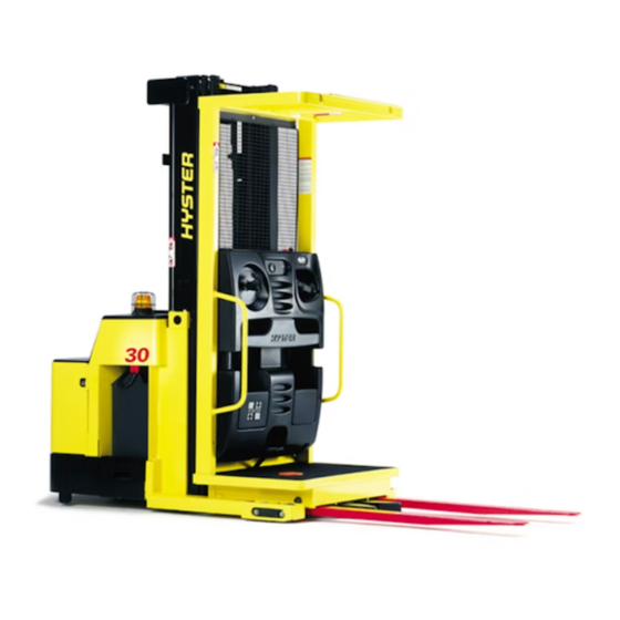
Hyster R30XMF3 Instruction Manual
Mast
Hide thumbs
Also See for R30XMF3
:
Service & repair manual
(28 pages)
1
2
Table Of Contents
3
4
5
6
7
8
9
10
11
12
13
14
15
16
17
18
19
20
21
22
23
24
25
26
27
28
29
page
of
29
Go
/
29
Contents
Table of Contents
Troubleshooting
Bookmarks
Table of Contents
Table of Contents
General
Forks
Replace
Operator Platform
Remove
Install
Two-Stage Mast
Remove
Disassemble
Clean and Inspect
Lift Cylinders
Assemble
Install
Three-Stage Mast
Remove
Disassemble
Clean and Inspect
Lift Cylinders
Assemble
Install
Load Wheels Replacement
Lift System Leak Check
Lift Chain Adjustment
Mast Adjustments
Operator Platform Adjustment
Troubleshooting
Advertisement
Quick Links
1
Table of Contents
2
General
3
Operator Platform
4
Troubleshooting
5
Operator Platform Adjustment
Download this manual
MAST
REPAIR
R30XMF3 [A169]; R30XMA3 [A185]; N40-50EA,
N40-45ER [C138]; R30E/EA, R30EA-FS [D118];
R30XMS2 [D174]; R30XMS3 [E174]; R30XM/XMA/XMF [F118];
R30XM2, R30XMA2, R30XMF2 [G118]; R30XM3 [H118]
PART NO. 1466835
4000 SRM 764
Table of
Contents
Previous
Page
Next
Page
1
2
3
4
5
Advertisement
Table of Contents
Need help?
Do you have a question about the R30XMF3 and is the answer not in the manual?
Ask a question
Questions and answers
Related Manuals for Hyster R30XMF3
Forklifts Hyster R30XMF3 Service & Repair Manual
Ac motor controller (28 pages)
Forklifts Hyster E174 Service Manual
(28 pages)
Forklifts Hyster D174 Service & Repair Manual
(24 pages)
Forklifts Hyster G118 Manual
(21 pages)
Forklifts Hyster R005 Service & Repair Manual
(25 pages)
Forklifts Hyster H4.0FT5 Service & Repair Manual
(25 pages)
Forklifts Hyster R30E Instruction Manual
Mast (29 pages)
Forklifts Hyster R30XMA Instruction Manual
Mast (29 pages)
Forklifts Hyster D435 Series Technical Information
(473 pages)
Forklifts Hyster J30XNT Operating Manual
(226 pages)
Forklifts Hyster Fortis S40FT Operating Manual
(224 pages)
Forklifts Hyster Narrow Aisle N30XMR3 Operating Manual
(71 pages)
Forklifts Hyster H40-60XT Operating Manual
(180 pages)
Forklifts Hyster MAST N50F Repair Manual
(52 pages)
Forklifts Hyster W40Z Quick Start Manual
(14 pages)
Forklifts Hyster T5ZAC Periodic Maintenance
(36 pages)
This manual is also suitable for:
R30xma3
N40-50ea
N40-45er
R30e
R30ea
R30ea-fs
...
Show all
R30xms2
R30xms3
R30xm
R30xma
R30xmf
R30xm2
R30xma2
R30xmf2
R30xm3
A169
A185
C138
D118
D174
E174
F118
G118
H118
Table of Contents
Print
Rename the bookmark
Delete bookmark?
Delete from my manuals?
Login
Sign In
OR
Sign in with Facebook
Sign in with Google
Upload manual
Upload from disk
Upload from URL


Need help?
Do you have a question about the R30XMF3 and is the answer not in the manual?
Questions and answers