Table of Contents
Advertisement
Advertisement
Table of Contents

Related Manuals for Hyster F007


Summary of Contents for Hyster F007
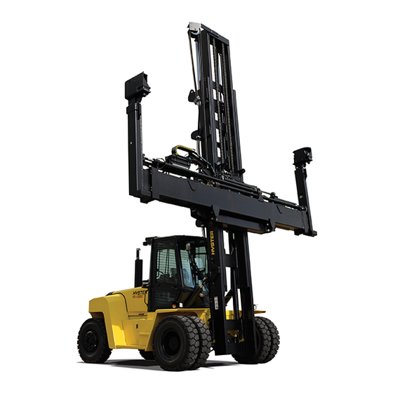
- Page 1 Hyster F007 (H170HD, H190HD, H210HD, H230HD, H250HD, H280HD) Forklift...
- Page 2 EMPTY CONTAINER HANDLING ATTACHMENT H10.00-12.00XM-12EC (H360HD-EC) [E019, F019] MODELS 553, 555, 558 PART NO. 1503241 5000 SRM 969...
- Page 3 • Use the correct tools for the job. • Keep the tools clean and in good condition. • Always use HYSTER APPROVED parts when making repairs. Replacement parts must meet or exceed the specifications of the original equipment manufacturer. • Make sure all nuts, bolts, snap rings, and other fastening devices are removed before using force to remove parts.
-
Page 4: Table Of Contents
Inspect ................................Remove ................................Install ................................Twist Locks Repair for Model 558........................Disassemble ..............................Clean and Inspect ............................Assemble ................................ Bleed the System ............................... Valve Assembly ..............................Slide Pad Replacement ............................Adjustments ............................... Twist Lock Angle Adjustment ........................©2003 HYSTER COMPANY... - Page 5 Thanks very much for your reading, Want to get more information, Please click here, Then get the complete manual NOTE: If there is no response to click on the link above, please download the PDF document first, and then click on it. Have any questions please write to me: admin@servicemanualperfect.com...
- Page 6 Table of Contents Empty Container Handling Attachment TABLE OF CONTENTS (Continued) Model 558 Only............................LOCKED/NOT LOCKED Sensors Adjustment.................... Model 553..............................Model 558..............................Seated Sensor Adjustment ..........................Model 553..............................Model 558..............................Overlowering Protection Sensor Adjustment (Models 553 and 558) ............Torque Chart ..............................Maintenance...............................
-
Page 7: General
5000 SRM 969 Operation General This section has the description and repair proce- • Model 553 with one pair of horizontally mounted dures for telescopic empty container handling attach- twist locks ment and operator controls. See Figure 1. Three • Model 555 with one pair of suspended hooks methods of engagement are covered in this section •... - Page 8 Operation 5000 SRM 969 Figure 1. Empty Container Attachment...
- Page 9 5000 SRM 969 Operation Legend for Figure 1 1. END BEAM ASSEMBLY 11. PIN, BOLT, NUT 2. WEAR PADS 12. EXTENSION CYLINDER ASSEMBLY 3. BRACKET 13. BRACKET, BOLT, NUT, WASHER, PIN, WASHER, 4. BRACKET COTTER PIN, PIN, SNAP RING 5. BOLT, WASHER 14.
- Page 10 Operation 5000 SRM 969 Figure 2. End Beam Assembly (Model 553)
- Page 11 5000 SRM 969 Operation Legend for Figure 2 1. PLATE 14. SENSOR 2. BOLT, LOCKWASHER 15. BUSHING 3. HOUSING 16. TWIST LOCK 4. END BEAM 17. SENSOR 5. HYDRAULIC MOTOR 18. SHOCK ABSORBER, NUT 6. RING 19. SOCKET HEAD SCREW 7.
-
Page 12: Extend And Retract Circuit
Operation 5000 SRM 969 EXTEND AND RETRACT CIRCUIT The attachments are designed to lift either 20- or 40-ft containers. The optional 30-ft stop kit allows lifting 30-ft containers. The 30-ft position is obtained by energizing the 30-ft stop while extending or re- tracting the beams. - Page 13 5000 SRM 969 Operation Figure 4. End Beam Assembly (Model 558)
-
Page 14: Model 558 - Vertically Mounted
Operation 5000 SRM 969 Legend for Figure 4 1. ROD END 28. TIE ROD END 2. RING PIN 29. BOLT, LOCKWASHER, NUT 3. SOCKET HEAD SCREW 30. ROD END 4. LOCKWASHER 31. CRANK 5. SENSOR 32. FLAG 6. SENSOR BRACKET, SPACER, SOCKET HEAD 33. -
Page 15: Indicator Lights And Leds
5000 SRM 969 Operation INDICATOR LIGHTS AND LEDS override feature for general lifting and trans- port of container. There are four indicator lights on left side of attach- ment and five LEDs in operator’s cab. See Figure 5 When attachment is seated and any of the twist locks and Figure 6. -
Page 16: Carriage And Attachment Repair
Attachment Without Carriage Repair 5000 SRM 969 Carriage and Attachment Repair REMOVE 3. Remove pin from each chain anchor at carriage. Disconnect lift chains from carriage. Attach a rope to ends of each lift chain to control their WARNING movement. When working on or near mast, see Safety Pro- cedures When Working Near Mast in Mast 4000 4. -
Page 17: Sideshift Cylinders Repair
5000 SRM 969 Sideshift Cylinders Repair 7. Remove top two wear blocks to allow easier re- will allow top bar of attachment frame to be re- moval of attachment. Slide lower frame of at- leased from the carriage. For further disassem- tachment forward so frame rotates slightly. -
Page 18: Extension Cylinders Repair
Extension Cylinders Repair 5000 SRM 969 Extension Cylinders Repair REMOVE 6. Inspect components and replace if necessary. 1. Retract attachment to 20-ft position. Shut down CLEAN AND INSPECT engine. See Figure 1 and Figure 8. WARNING 2. Disconnect hydraulic lines at chain end (42) and Cleaning solvents can be flammable and toxic put caps on open lines. - Page 19 5000 SRM 969 Extension Cylinders Repair Figure 8. Extension Cylinder...
-
Page 20: Vertical End Beams Repair
Vertical End Beams Repair 5000 SRM 969 Legend for Figure 8 1. BALL JOINT 22. SEAL RING 2. SNAP RING 23. O-RING 3. PISTON ROD 24. SCREW 4. WIPER RING 25. BRACKET 5. WASHER 26. BOLT 6. RING 27. NUT 7. -
Page 21: Twist Locks Repair For Model 553
5000 SRM 969 Twist Locks Repair for Model 553 3. Replace any defective hoses or cables and tape separately in order to follow bend in tube. Make sure hoses, cable, and string together. each hose is marked. NOTE: Tape hoses and cables in such a way that each 4. -
Page 22: Hooks Replacement For Model 555
Hooks Replacement for Model 555 5000 SRM 969 7. Position hydraulic motor with key (23) and fasten 8. Connect hydraulic lines and electrical connec- in place with four socket head screws. tions. Hooks Replacement for Model 555 INSPECT REMOVE 1. Remove nut and washer that holds hook in place. WARNING The lifting hooks are safety critical compo- 2. -
Page 23: Twist Locks Repair For Model 558
5000 SRM 969 Twist Locks Repair for Model 558 Figure 10. Hook Wear Twist Locks Repair for Model 558 DISASSEMBLE CLEAN AND INSPECT 1. Remove cover (43). See Figure 4. WARNING Cleaning solvents can be flammable and toxic 2. Remove wiring to sensors and identify location. and can cause skin irritation. -
Page 24: Assemble
Bleed the System 5000 SRM 969 assembly by means of a jack or other suitable device to make sure assembly does not fall out. 5. Install collets with sloping side facing up. 6. Install key and roll pin in keyway of twist lock. NOTE: To ease in installation of crank to twist lock, make two alignment pins using M8×75 bolts or socket head screws with heads removed. -
Page 25: Valve Assembly
5000 SRM 969 Slide Pad Replacement Valve Assembly NOTE: The 140-bar relief valve is located on top of carriage. 1. Loosen lock nut. See Figure 12. 2. Turn bolt clockwise to raise pressure. Turn bolt counterclockwise to lower pressure. 3. Tighten lock nut. 1. -
Page 26: Adjustments
Adjustments 5000 SRM 969 1. EXTENSION CYLINDER SUPPORT 4. LOWER SIDESHIFT SLIDE PADS 2. MAIN FRAME AND EXTENSION BEAM 5. END BEAM SLIDE PADS 3. UPPER SIDESHIFT SLIDE PADS Figure 13. Slide Pads Adjustments TWIST LOCK ANGLE ADJUSTMENT 6. Loosen bolts (29) at tie rod end (28) and adjust to required length by turning rod end on cylinder Model 558 Only assembly (11). -
Page 27: Model 558
5000 SRM 969 Adjustments 2. Adjust space between sensor and ring to 1 mm 3. Turn adjustment screw clockwise to increase dis- (0.039 in.) using a feeler gauge. tance. 3. Tighten four bolts holding sensors. 4. Turn adjustment screw counterclockwise to de- crease distance. -
Page 28: Torque Chart
Maintenance 5000 SRM 969 TORQUE CHART Table 1. Torque Chart Item to be Torqued Torque Value Twist Lock Cylinder Assembly Screws 38 N•m (28 lbf ft) Stop Cylinder Assembly Screws 38 N•m (28 lbf ft) Stop Cylinder Piston Securing Nut 60 N•m (44 lbf ft) Extension Cylinder Piston Securing Nut 450 N•m (332 lbf ft) - Page 29 5000 SRM 969 Maintenance Table 2. Maintenance Schedule Item Item 250 Hr/ 500 Hr/ 1000 Hr/ 2000 Hr/ Procedure or Specification 1 Mo 3 Mo 6 Mo 1 Yr Quantity Wear Pads for Check for Multipurpose Main Beams and wear of 14 Grease Extension Beams nylon pads and...
-
Page 30: Additional Attachment Maintenance
Maintenance 5000 SRM 969 Table 2. Maintenance Schedule (Continued) Item Item 250 Hr/ 500 Hr/ 1000 Hr/ 2000 Hr/ Procedure or Specification 1 Mo 3 Mo 6 Mo 1 Yr Quantity Twist Lock Check for wear Multipurpose Assemblies and possible Grease Model 558 damage of twist... -
Page 31: Interface Boxes
5000 SRM 969 Maintenance INTERFACE BOXES Model 555 NOTE: Box is on left side, positioned on extension cylinder. See Figure 21. Interface Function Indication Status Green SpB5 Indicates +24V supply voltage present ON When Present Yellow SpB5 Indicates command extend LH present ON When Present Yellow SpB5... - Page 32 Maintenance 5000 SRM 969 Interface Function Indication Status Green SpB6 Indicates +24V supply voltage present ON When Present Yellow SpB6 Indicates command lock twist lock RH ON When Present present Yellow SpB6 Indicates command unlock twist lock RH ON When Present present Yellow SpB6...
-
Page 33: Troubleshooting
5000 SRM 969 Troubleshooting Troubleshooting PROBLEM POSSIBLE CAUSE PROCEDURE OR ACTION No attachment functions or Check lift truck hydraulic supply Repair supply valve. no attachment functions in valve for correct operation. one direction. Low main hydraulic pressure at at- Adjust pressure at main relief valve tachment main relief valve. - Page 34 Troubleshooting 5000 SRM 969 PROBLEM POSSIBLE CAUSE PROCEDURE OR ACTION One extension beam will not No electrical power at solenoid valve Check for proper voltage at solenoid. retract. mounted on rear of extension cylin- If voltage is present, replace solenoid. der.
- Page 35 5000 SRM 969 Troubleshooting PROBLEM POSSIBLE CAUSE PROCEDURE OR ACTION One or all indicator lights do Electric circuit of a particular func- Check for blown fuses or loose con- not function. (Cont.) tion is open. nectors. Check proper functioning of printed circuit board.
-
Page 36: Diagrams, Schematics, Or Arrangements
Diagrams, Schematics, or Arrangements 5000 SRM 969 Figure 15. Hydraulic System Model 553... - Page 37 5000 SRM 969 Diagrams, Schematics, or Arrangements Legend for Figure 15 1. HYDRAULIC MOTOR 14. SIDESHIFT ASSEMBLY 2. FITTING, O-RING 15. FITTING, O-RING 3. HOSE ASSEMBLY 16. HOSE ASSEMBLY 4. HOSE ASSEMBLY 17. HOSE ASSEMBLY 5. HOSE ASSEMBLY 18. VALVE ASSEMBLY 6.
- Page 38 Diagrams, Schematics, or Arrangements 5000 SRM 969 Figure 17. Hydraulic System Model 558...
- Page 39 5000 SRM 969 Diagrams, Schematics, or Arrangements Legend for Figure 17 1. HOSE ASSEMBLY 12. HOSE ASSEMBLY 2. TWIST LOCK CYLINDER ASSEMBLY 13. HOSE ASSEMBLY 3. FITTING, O-RING 14. SIDESHIFT ASSEMBLY 4. HOSE ASSEMBLY 15. FITTING, O-RING 5. HOSE ASSEMBLY 16.
- Page 40 Diagrams, Schematics, or Arrangements 5000 SRM 969 Figure 18. Hydraulic Diagram - Horizontal Twist Lock Model 553...
- Page 41 5000 SRM 969 Diagrams, Schematics, or Arrangements Figure 19. Hydraulic Diagram - Suspended Hooks Model 555...
- Page 42 Diagrams, Schematics, or Arrangements 5000 SRM 969 Figure 20. Hydraulic Diagram - Vertical Twist Lock Model 558...
- Page 43 5000 SRM 969 Diagrams, Schematics, or Arrangements Figure 21. Electric Diagram...
- Page 44 Diagrams, Schematics, or Arrangements 5000 SRM 969 Legend for Figure 21 1. INTERFACE BOX 16. CABLE ASSEMBLY 2. SENSOR 17. CABLE ASSEMBLY 3. SENSOR 18. PRINTED CIRCUIT 4. CABLE ASSEMBLY 19. PRINTED CIRCUIT 5. BEAM LIGHT 20. STANDARD CARD 6. INTERFACE BOX 21.
- Page 45 5000 SRM 969 Diagrams, Schematics, or Arrangements Figure 22. Wiring Diagram...
- Page 46 Diagrams, Schematics, or Arrangements 5000 SRM 969 Figure 23. Electric Schematic Diagram...
- Page 48 TECHNICAL PUBLICATIONS 5000 SRM 969 9/03 (8/01) Printed in U.S.A.
Need help?
Do you have a question about the F007 and is the answer not in the manual?
Questions and answers