
Related Manuals for Boss Snowplow Snowrator Scout SNR24200


Summary of Contents for Boss Snowplow Snowrator Scout SNR24200
- Page 1 Form No. MSC28010 Rev A Owner's Manual Snowrator ® Scout Part No. SNR24200 *MSC28010* Register at www.bossplow.com. Original Instructions (EN)
- Page 2 Introduction This product complies with all relevant European directives; for details, please see the separate product specific Declaration of Conformity (DOC) sheet. This stand-on vehicle is intended to be used by professional, hired operators. It is designed primarily BOSS Products limited consumer warranty and BOSS Products commercial warranty policies are located at for plowing snow on residential or commercial www.bossplow.com.
-
Page 3: Safety-Alert Symbol
Safety-Alert Symbol The safety-alert symbol (Figure 2) shown in this manual and on the machine identifies important safety messages that you must follow to prevent accidents. g000502 Figure 2 Safety-alert symbol The safety-alert symbol appears above information that alerts you to unsafe actions or situations and is followed by the word DANGER, WARNING, or CAUTION. -
Page 4: Table Of Contents
Contents Draining the Hydraulic Fluid and Replacing the Filter............34 Adding Hydraulic Fluid........35 Safety-Alert Symbol..........3 Plow Maintenance..........36 Safety ............... 5 Checking the Cutting Edge ....... 36 General Safety ........... 5 Flipping the Cutting Edge........36 Safety and Instructional Decals ......5 Storage .............. -
Page 5: Safety
Safety • Do not allow children to operate the machine. Allow only people who are responsible, trained, familiar with the instructions, and physically General Safety capable to operate the machine. • Stop the machine, engage the parking brake, Always follow all safety instructions to avoid serious shut off the engine, and remove the key before personal injury. - Page 6 decal143-4601 143-4601 1. Engine—stop 3. Engine—start 2. Engine—run decal143-4602 143-4602 1. Engine speed—fast 2. Engine speed—slow decal143-4766 143-4766 1. Warning—read the Owner’s Manual. 8. Warning—engage the parking brake, lower the attachment, shut off the engine, and remove the key before leaving the machine.
- Page 7 decal143-4604 143-4604 1. Hour meter 3. Neutral 2. Parking brake 4. Low-voltage indicator decal143-4603 143-4603 1. Joystick left—angles the 4. Joystick right—angles the plow right plow left 2. Joystick forward into 5. Joystick back—raises the plow detent—activates plow position LOAT 3.
- Page 8 decalmsc27245 MSC27245 1. Warning—stay away from moving parts; keep all guards and shields in place...
-
Page 9: Setup
Checking the Engine-Oil Setup Level Note: Determine the left and right sides of the Before you start the engine and use the machine, machine from the normal operating position. check the oil level in the engine crankcase; refer to Checking the Engine-Oil Level (page 25). -
Page 10: Installing The Battery
Installing the Battery WARNING Incorrect battery cable routing could damage the machine and cables, causing sparks. Sparks can cause the battery gases to explode, resulting in personal injury. • Always disconnect the negative (black) battery cable before disconnecting the positive (red) cable. •... -
Page 11: Product Overview
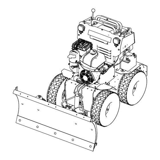
Product Overview g485661 Figure 6 1. Control panel 5. Plow 2. Platform latch 6. Fuel tank 3. Operator platform 7. Battery 4. Parking brake 8. Air filter Controls Become familiar with all the controls before you start the engine and operate the machine. g486063 Figure 7 1. - Page 12 Parking Brake g424699 Figure 8 g425515 Figure 9 1. Disengage 2. Engage 1. Safety-interlock symbols 3. Low-voltage indicator 2. Hour meter Throttle Lever Safety-Interlock Indicators The throttle lever controls the speed (rpm) of the engine. It has a continuous-variable setting from the The black triangle symbols on the hour meter indicate to F position.
-
Page 13: Engine Controls
Engine Controls Specifications Note: Specifications and design are subject to change without notice. Plow width 1.2 m (48 inches) Plow height 55.8 cm (22 inches) Machine width 86.4 cm (34 inches) Machine length 1.8 m (70-1/2 inches) Machine height 1.2 m (47-1/2 inches) Weight 385.5 kg (850 lb) Attachments/Accessories... -
Page 14: Before Operation
Operation – Avoid prolonged breathing of vapors. – Keep your hands and face away from the nozzle and the fuel-tank opening. Before Operation – Keep fuel away from your eyes and skin. • Do not store the machine or fuel container where Before Operation Safety there is an open flame, spark, or pilot light, such as on a water heater or on other appliances. -
Page 15: Performing Daily Maintenance
Filling the Fuel Tank During Operation Capacity: 7 L (1.9 US gallons) General Safety Park the machine on a level surface, move the motion-control levers to the N position, EUTRAL • The owner/operator can prevent and is responsible engage the parking brake, shut off the engine, for accidents that may cause personal injury or wait for all moving parts to stop, and remove property damage. -
Page 16: Slope Safety
• • Before leaving the operating position, do the Do not operate a machine under any conditions following: where traction, steering, or stability is in question. Be aware that operating the machine across – Park the machine on a level surface. slopes or downhill may cause the machine to lose –... -
Page 17: Shutting Off The Engine
g008610 Figure 14 1. Off 3. Start 2. On g486109 Figure 12 Turn the key to the S position and hold it TART there until the engine starts. If the engine does not start within 5 seconds, Operate the choke knob as follows: release the key and wait at least 15 seconds •... -
Page 18: Driving Forward Or Backward
Driving Forward or Backward The throttle control regulates the engine speed as measured in rpm. Place the throttle control in the position for best performance. CAUTION The machine can spin very rapidly, and you may lose control of the machine, causing personal injury to you and damage to the machine. -
Page 19: After Operation
Pushing the Machine by ground. The joystick stays in the F position LOAT until it is centered again. Hand After Operation The bypass valves allow you to push the machine by hand without the engine running. Important: Always push the machine by hand. After Operation Safety Do not tow the machine, because hydraulic damage may occur. -
Page 20: Transporting The Machine
Selecting a Trailer WARNING Loading a machine onto a trailer or truck increases the possibility of tip-over and could cause serious injury or death (Figure 21). • Use only a full-width ramp; do not use individual ramps for each side of the machine. - Page 21 Loading the Machine WARNING Loading a machine onto a trailer or truck increases the possibility of tip-over and could cause serious injury or death. • Use extreme caution when operating a machine on a ramp. • Back the machine up the ramp and walk it forward down the ramp.
-
Page 22: Maintenance
Maintenance Note: Determine the left and right sides of the machine from the normal operating position. Important: Refer to your engine owner’s manual for additional maintenance procedures. WARNING Failing to properly maintain the machine could result in premature failure of machine systems, causing possible harm to you or bystanders. -
Page 23: Pre-Maintenance Procedures
Maintenance Service Maintenance Procedure Interval • Check, clean and gap the spark plug. Every 160 hours • Replace the paper air-cleaner element (more frequently in dusty conditions). Every 300 hours • Service the air cleaner. • Check the tire pressure. •... -
Page 24: Removing The Cushion For Rear Access
Removing the Cushion for Engine Maintenance Rear Access Engine Safety You can release the cushion for rear access to the • Shut off the engine before checking the oil or machine for maintenance or adjustment. adding oil to the crankcase. Pull up on the bottom of the cushion and slide •... -
Page 25: Servicing The Engine Oil
Remove the foam pre-cleaner, wash it with a Allow the engine to cool. mild detergent and water, and then blot it dry. Check the engine-oil level as shown in Figure Remove and inspect the paper air filter; if it is excessively dirty, discard it.. -
Page 26: Servicing The Spark Plug
Park the machine so that the drain side is slightly lower than the opposite side to ensure that the oil drains completely. Lower the plow, shut off the engine, remove the key, and wait for all moving parts to stop before leaving the operating position. - Page 27 Removing the Spark Plug Installing the Spark Plug Lower the plow, shut off the engine, remove the Tighten the spark plug(s) to 22 N∙m (16 ft-lb). key, and wait for all moving parts to stop before leaving the operating position. Remove the spark plug as shown in Figure g027478...
-
Page 28: Electrical System Maintenance
Electrical System WARNING Incorrect battery cable routing could Maintenance damage the machine and cables, causing sparks. Sparks can cause the battery gases to explode, resulting in personal Electrical System Safety injury. • Disconnect the battery or remove the spark-plug • Always disconnect the negative wire before making any repairs. - Page 29 g000538 Figure 36 1. Positive battery post 3. Red (+) charger lead 2. Negative battery post 4. Black (-) charger lead Installing the Battery g486612 Figure 35 WARNING 1. Positive (red) 2. Negative (black) Incorrect battery cable routing could damage the machine and cables, causing sparks.
-
Page 30: Servicing The Fuses And Relays
Servicing the Fuses and Relays The electrical system is protected by fuses and relays. It requires no maintenance. If a fuse or relay blows, check the component or circuit for a malfunction or short. Replacing the Fuse-Box Relays and Fuses There are 3 fuses and 2 relays in the fuse box. - Page 31 Replacing the In-Line Fuse There is a replaceable in-line fuse on the wire harness. Remove the cushion. Remove the left guard by removing the 3 bolts. g489321 Figure 40 Remove and inspect the fuse or relay. If the fuse or relay is burnt out, discard it and install a new fuse or relay with the same rating;...
-
Page 32: Drive System Maintenance
Drive System Remove and inspect the fuse. If the fuse is burnt out, discard it and install a Maintenance new fuse with the same rating (30 A). Important: Do not use a fuse with a rating Checking the Tire Pressure higher than the original fuse;... -
Page 33: Hydraulic System Maintenance
Checking the Hydraulic Hydraulic System Fluid Maintenance Service Interval: After the first 5 hours—Check the hydraulic-fluid level. Hydraulic System Safety Every 100 hours—Check the hydraulic hoses • Seek immediate medical attention if fluid is injected and fittings for leaks. into skin. Injected fluid must be surgically removed Check the hydraulic fluid level when the fluid is cold. -
Page 34: Draining The Hydraulic Fluid And Replacing The Filter
Draining the Hydraulic Fluid and Replacing the Filter Service Interval: After the first 100 hours—Change the hydraulic filters and hydraulic fluid. Change the hydraulic fluid more frequently in severe conditions. Contact your Authorized Service Dealer for a hydraulic kit to replace the hydraulic filters. WARNING Hot hydraulic fluid can cause severe burns. -
Page 35: Adding Hydraulic Fluid
Adding Hydraulic Fluid Install the cushion. Clean the area around the hydraulic-reservoir cap. Remove the hydraulic-tank cap. g489333 Figure 48 Slowly add fluid to the hydraulic tank until it is to the fill mark (approximately 1/2 full). Important: Use the fluid specified in Hydraulic System Specifications (page 33). -
Page 36: Plow Maintenance
Plow Maintenance Storage Storage Safety Checking the Cutting Edge • Let the engine cool before storing the machine. Service Interval: Before each use or daily—Check • Do not store the machine or fuel near flames or the cutting edge for wear. drain the fuel indoors. -
Page 37: Removing The Machine From Storage
Lightly sand and use touch-up paint on painted areas that are scratched, chipped, or rusted. Loosen the trip-return springs. Store the machine in a clean, dry, garage or storage area. Remove the key from the engine key switch and store it in a memorable place. Cover the machine to protect it and keep it clean. -
Page 38: Troubleshooting
Troubleshooting Problem Possible Cause Corrective Action The engine does not start, starts hard, or 1. The fuel tank is empty or the shutoff 1. Fill the fuel tank with fuel and open the fails to keep running. valve is closed. valve. - Page 39 California Proposition 65 Warning Information What is this warning? You may see a product for sale that has a warning label like the following: WARNING: Cancer and Reproductive Harm—www.p65Warnings.ca.gov. What is Prop 65? Prop 65 applies to any company operating in California, selling products in California, or manufacturing products that may be sold in or brought into California.
Need help?
Do you have a question about the Snowrator Scout SNR24200 and is the answer not in the manual?
Questions and answers