Table of Contents
Advertisement
Quick Links
Installation Instructions
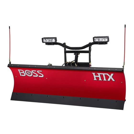
RT3 HTX Straight-Blade Plow
Part No. STB08980—Serial No. 400000000 and Up
Part No. STB08980B—Serial No. 400000000 and Up
Part No. STB10321C—Serial No. 400000000 and Up
Part No. STB15035—Serial No. 400000000 and Up
Part No. STB18900—Serial No. 400000000 and Up
Part No. STB19838—Serial No. 400000000 and Up
Part No. STB19838B—Serial No. 400000000 and Up
Register at www.bossplow.com.
Original Instructions (EN)
Form No. STB10145 Rev D
*STB10145* D
Advertisement
Table of Contents

Subscribe to Our Youtube Channel
Related Manuals for Boss Snowplow STB08980


Summary of Contents for Boss Snowplow STB08980
- Page 1 Form No. STB10145 Rev D Installation Instructions RT3 HTX Straight-Blade Plow Part No. STB08980—Serial No. 400000000 and Up Part No. STB08980B—Serial No. 400000000 and Up Part No. STB10321C—Serial No. 400000000 and Up Part No. STB15035—Serial No. 400000000 and Up Part No. STB18900—Serial No. 400000000 and Up Part No.
-
Page 2: Table Of Contents
Date WARNING Purchased CALIFORNIA Model No. Proposition 65 Warning This product contains a chemical Serial No. or chemicals known to the State of California to cause cancer, birth defects, Blade Crate or reproductive harm. Serial No. This manual identifies potential hazards and has safety messages identified by the safety-alert symbol (Figure 2), which signals a hazard that may cause... -
Page 3: Safety
• Do not exceed 8 km/h (5 mph) when D-Force is installation. For recommended vehicle models, activated (if equipped). refer to the BOSS Snowplow Application Chart • Always lower the blade when the vehicle is not in and Selection Guide. -
Page 4: Safety And Instructional Decals
Safety and Instructional Decals Safety decals and instructions are easily visible to the operator and are located near any area of potential danger. Replace any decal that is damaged or missing. decalmsc04604-5 MSC04604-5 1. Read the Owner’s 4. Read the Owner’s Manual for information Manual for information on attaching the plow. - Page 5 decalmsc06354 MSC06354 decalmsc01868 MSC01868 1. Warning—read the Owner’s Manual. 6. Crushing hazard—do not stand between the plow and vehicle during maintenance. 2. Warning—all operators should be trained before operating 7. Warning—do not exceed 64 km/h (40 mph) when transporting the machine. the plow.
-
Page 6: Installation
Installation Note: Determine the left and right sides of the machine from the normal operating position. Installing the Push Frame and Coupler Tower Attach the front of the push-frame assembly to the plow blade using 2 bolts (5/8 x 4 inches) and self-locking nuts (Figure 3). -
Page 7: Installing The Hydraulic Hoses
g032919 Figure 8 1. 90° fitting 4. Middle fitting g032918 2. 86 cm (34 inch) hose 5. Right fitting Figure 7 3. Left fitting 6. 45 cm (18 inch) hose 1. Clevis pin 4. Lift cylinder 2. Push-frame assembly 5. Coupler tower Install the 3/8 inch O-ring end of the 45 cm (18 3. -
Page 8: Installing The Light Bar
g032921 g032920 Figure 10 Figure 9 1. Light bar 3. Coupler tower 1. 39 cm (15-1/2 inch) hose 3. Rear fitting 2. Self-locking nuts (3/8 inch) 4. Bolts (3/8 x 1-1/4 inch) 2. Upper lift-cylinder fitting Ensure that the end caps are installed on the Using thread compound, install one end of the ends of the light bar (Figure... -
Page 9: Installing The Blade Guides And Filling The Hydraulic Reservoir
Secure the left headlight to the headlight bracket using 4 bolts (1/4 x 3/4 inch), split lock washers, and flat washers (Figure 11). Important: Do not use thread-locking compound on these bolts. Note: Do not tighten the fasteners at this time. Repeat steps for the right headlight bracket and headlight. -
Page 10: Installing The Wire Harness
Slowly fill the reservoir with BOSS Connect the blue plug from the long wire high-performance hydraulic fluid until it harness to the back of the left vehicle headlight accepts no more. (Figure 15). Connect the black plug from the long wire Note: The reservoir holds approximately 1.9 L harness to the previously disconnected plug on... - Page 11 g032927 Figure 17 g032928 1. Plow controller 4. Black wires Figure 18 5. Headlight toggle switch 2. Controller connector 1. White/black wire 4. Pump solenoid 3. Black/red wire 2. Battery cable 5. Brown wire 3. Red power/ground cable Connect the 2 black wires to the headlight toggle switch (Figure 17).
- Page 12 Mount the relay pack to the inside of the engine compartment using 4 sheet-metal screws (Figure 21). Note: Ensure that the relay pack is mounted in the upright position. g212209 Figure 19 1. Black power/ground cable 4. Red fused wire 2.
-
Page 13: Installing The Headlight Adapters
Note: • If the red/white wire is installed Switch the vehicle headlights to the incorrectly, the low beams do not illuminate position. BEAM when the plow high-beams are on. • Switch the plow headlight toggle switch to the P position. Models Wire Placement •... -
Page 14: Mounting The Plow Controller
Connect the headlight adapter to the back of the Grease, tuck, and secure the previously left vehicle headlight (Figure 22). disconnected high-beam plug on the vehicle wire harness (Figure 23). Connect the black plug from the headlight adapter to the long wire harness (Figure 22). - Page 15 g032937 Figure 24 Mounting the SmartTouch2™ Controller Note: Mount the controller in the cab in a dry area where it does not interfere with vehicle operation or visibility. Important: Do not install the swivel mount when g032942 temperatures are below 16 °C (60 °F). Figure 25 1.
-
Page 16: Adjusting The Pushbeam Height
Aiming the Headlights Let the swivel mount rest unused for 72 hours before sliding the controller into the mounting Important: bracket. Certify that the installation of the snowplow lights conforms to applicable federal Important: Mounting the controller motor vehicle safety standards. immediately may cause the adhesive to fail. -
Page 17: Product Overview
Product Overview Mark the vertical headlight centerline on the screen (Figure 27). Mark the horizontal headlight centerline on the screen (Figure 27). Note: The horizontal headlight centerline should be the distance from the ground to the center of the headlight. Adjust the plow headlights until the brightest part of the plow low-beam lights are aligned as shown in... - Page 18 SmartHitch2 Switch • switch—turns the plow controller on and off. A red light will illuminate when the controller The SmartHitch2 switch controls the movement of is on. the coupler tower to facilitate plow attachment and Note: Turn off the controller when not in use to removal.
-
Page 19: Operation
SmartTouch2 Controller Operation The SmartTouch2 controller operates the movement of the snowplow. Note: Determine the left and right sides of the machine from the normal operating position. Note: Plows equipped with D-Force must have a SmartTouch2 controller with a red center button. Mounting the Snowplow Note: The vehicle must be running before starting... -
Page 20: Checking The Hydraulic Fluid Level
Push the SmartHitch2 switch on the side of the coupler tower upward and raise the tower until the coupler spring pins snap in (Figure 35). g032912 Figure 35 1. Kickstand 3. Coupler tower 2. SmartHitch2 switch 4. Coupler spring pin Ensure that both coupler spring pins have fully g032934 engaged the coupler... - Page 21 g032935 Figure 37 1. Fill elbow Install the previously removed fill cap. Start the vehicle and operate the plow in its full range of movement. Stop the vehicle, check the hydraulic-fluid level, and replenish the fluid if necessary; refer to Checking the Hydraulic Fluid Level (page 20).
-
Page 22: Troubleshooting
Troubleshooting Problem Possible Cause Corrective Action The pump motor does not run. 1. Check that the power/ground cables 1. Connect the cables if they are not and control cables are connected connected. properly. 2. Check for voltage at the pump motor 2. - Page 23 Problem Possible Cause Corrective Action The plow does not raise or raises slowly. 1. Check the hydraulic-fluid level. 1. The hydraulic-fluid level should be within 2 cm (3/4 inch) of the top of the reservoir when lowered. 2. Check that the power/ground cables 2.
- Page 24 Problem Possible Cause Corrective Action The plow lights are dim, do not come on, 1. Check the electrical connections. 1. Clean and repair any corroded or or flicker. damaged terminals. 2. Check the headlight adapter wires. 2. Verify that the proper headlight adapters are being used and are correctly installed.
-
Page 25: Schematics
Schematics g037873 Plow Side Electrical Schematic (Rev. 0) - Page 26 g037874 Truck Side Electrical Schematic (Rev. 0)
- Page 27 g037888 Function Wire Color Green Blade left Blade right White Lift Lower Orange Red/Black Blade right Blue Blade left Black SmartHitch2 Brown Ground Non-D-Force Plow Hydraulic Manifold Wiring (Rev. 0)
- Page 28 g212234 Ref. Part Number Qty. Description HYD07059 Nut, Coil — used with valve HYD01637 & HYD07100 HYD01638 Coil, Hydraulic Valve HYD01640 Check Valve HYD01637 Hydraulic Valve, Lift/Lower Cartridge HYD07048 Hydraulic Valve, Flow Control Cartridge HYD07122 Hydraulic Valve Assembly with SmartHitch2 (Red) HYD07100 Hydraulic Valve, Angle Cartridge (3 Position - 4 Way Spool) HYD07027...
- Page 29 g212706 Wire Color Function Green Blade left Red/Black Blade right White Lift Orange Lower Communication Blue Module power Black SmartHitch2 Brown Ground D-Force Blue/White Red/Green Unused Red/Blue Unused Blue/Green Unused D-Force Plow Hydraulic Manifold Wiring (Rev. 0)
- Page 30 g238701 Ref. Part Number Qty. Description HYD07059 Nut, Coil - used with valve HYD01637 & HYD07100 HYD01638 Coil, Hydraulic Valve HYD07060 Nut, Coil - used with valve HYD07047 HYD10174 Relief Valve, Hydraulic D-Force HYD01640 Check Valve HYD01637 Valve, Cartridge Lift Angle HYD07047 Hydraulic Valve, SmartHitch2 Attach HYD07027...
- Page 31 Notes:...
- Page 32 Notes:...
- Page 33 Notes:...
- Page 34 European Privacy Notice The Information Toro Collects Toro Warranty Company (Toro) respects your privacy. In order to process your warranty claim and contact you in the event of a product recall, we ask you to share certain personal information with us, either directly or through your local Toro company or dealer. The Toro warranty system is hosted on servers located within the United States where privacy law may not provide the same protection as applies in your country.
- Page 35 Products which have been subject to misuse, negligence, accident, improper installation, maintenance, care, or storage. Products mounted on vehicles other than those listed in the BOSS Snowplow Application Chart and Selection Guide. BOSS Products does not assume liability for damage to your motor vehicle resulting from the attachment or use of any BOSS products. Vehicle risk is the sole responsibility of the purchaser.
- Page 36 Products which have been subject to misuse, negligence, accident, improper installation, maintenance, care, or storage. Products mounted on vehicles other than those listed in the BOSS Snowplow Application Chart and Selection Guide. BOSS Products does not assume liability for damage to your motor vehicle resulting from the attachment or use of any BOSS products. Vehicle risk is the sole responsibility of the purchaser.
Need help?
Do you have a question about the STB08980 and is the answer not in the manual?
Questions and answers