
Related Manuals for Boss Snowplow Snowrator SNR24001


Summary of Contents for Boss Snowplow Snowrator SNR24001
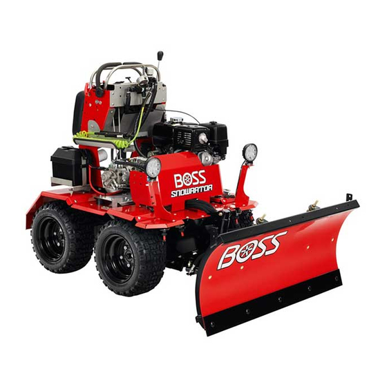
- Page 1 Form No. 3432-107 Rev B Owner's Manual Snowrator Part No. SNR24001—Serial No. 400000000 and Up *3432-107* B Register at www.bossplow.com. Original Instructions (EN)
- Page 2 This product complies with all relevant European directives; for details, please see the separate product specific Declaration of Conformity (DOC) sheet. BOSS Products limited consumer warranty and BOSS Products commercial warranty policies are located at www.bossplow.com. Patents pending. WARNING CALIFORNIA g294659 Proposition 65 Warning Figure 1...
-
Page 3: Table Of Contents
Contents Electrical System Maintenance ......33 Electrical System Safety ........33 Servicing the Battery......... 33 Safety ............... 4 Servicing the Fuses .......... 35 General Safety ........... 4 Drive System Maintenance ........36 Safety and Instructional Decals ......4 Checking the Tire Pressure....... 36 Setup ................ -
Page 4: Safety
Safety familiar with the instructions, and physically capable to operate the machine. • Stop the machine, shut off the engine, and remove General Safety the key before servicing, fueling, or unclogging the machine. Always follow all safety instructions to avoid serious personal injury. - Page 5 decal143-0013 143-0013 1. Plow—angle left 10. Hour meter 2. Plow—float 11. Speedometer 3. Plow—lower/D-Force 12. Voltage 4. Plow—angle right 13. Lights 5. Plow—raise 14. Sprayer pump 6. Fast 15. On 7. Slow 16. Off 8. Neutral 17. Operator presence sensor 9.
- Page 6 decal143-0674 143-0674 1. Warning—read the Owner’s Manual. 8. Warning—shut off the sprayer pump, put the machine in the position, shut off the engine, and remove the key EUTRAL before leaving the machine; lower the plow when the machine is not in use. 2.
-
Page 7: Setup
Checking the Engine-Oil Setup Level Note: Determine the left and right sides of the machine from the normal operating position. Before you start the engine and use the machine, check the oil level in the engine crankcase; refer to Checking the Engine-Oil Level (page 29). -
Page 8: Charging The Battery
Charging the Battery WARNING Charging the battery produces gasses that can explode and cause serious injury. • Keep cigarettes, sparks, and flames away from the battery. • Make sure that the ignition switch is off. • Ventilate when charging or using the battery in an enclosed space. -
Page 9: Product Overview
Product Overview g295494 Figure 7 1. Air filter 5. Cushion 2. Fuel tank 6. Sprayer tank 3. Key switch 7. Battery 4. Spray gun... -
Page 10: Controls
Controls Motion-Control Levers Use the motion-control levers to drive the machine Become familiar with all the controls before you start forward, reverse, and turn either direction. the engine and operate the machine. Plow Joystick The plow joystick is located on the left side of the machine. -
Page 11: Specifications
Information Display Key Switch The key switch starts and stops the engine. This The information display shows the time, operating switch is located on the side of the engine. Rotate the hours, engine speed, and battery voltage of the key switch to the S position to start the engine. -
Page 12: Before Operation
Operation your Authorized Service Dealer or authorized BOSS distributor or go to www.bossplow.com for a list of all approved attachments and accessories. Before Operation To ensure optimum performance and continued safety of the machine, use only genuine BOSS replacement parts and accessories. Replacement parts and Before Operation Safety accessories made by other manufacturers could be dangerous, and such use could void the product... -
Page 13: Adding Fuel
Filling the Fuel Tank – Store fuel in an approved container and keep it out of the reach of children. Capacity: 6.1 L (1.6 US gallons) • Fuel is harmful or fatal if swallowed. Long-term Park the machine on a level surface, move the exposure to vapors can cause serious injury and motion-control levers to the N position,... -
Page 14: Filling The Sprayer Tank
Filling the Sprayer Tank During Operation Capacity: 75 L (20 US gallons) General Safety Clean around the tank cap (Figure 12). • The owner/operator can prevent and is responsible for accidents that may cause personal injury or property damage. • Wear appropriate clothing, including hearing and eye protection;... -
Page 15: Slope Safety
• • Never leave a running machine unattended. Do not operate a machine under any conditions where traction, steering, or stability is in question. • Before leaving the operating position, do the Be aware that operating the machine across following: slopes or downhill may cause the machine to lose –... -
Page 16: Starting The Engine
Starting the Engine • To start a cold engine, move the choke lever to the C position. LOSED Important: Do not engage the starter for more • To start a warm engine, move the choke than 5 seconds at a time. If the engine fails to lever to the O position. -
Page 17: Shutting Off The Engine
WARNING CAUTION If you are thrown from the machine The machine can spin very rapidly, and you while not properly wearing the kill cord, may lose control of the machine, causing the machine can continue moving, personal injury to you and damage to the which may seriously injure you or other machine. -
Page 18: Operating The Plow
allowing the plow blade to follow the contour of the ground. The joystick stays in the F position LOAT until it is centered again. Operating the Sprayer Drive to the location where you will be spraying. Turn the sprayer pump on (Figure 19). -
Page 19: Using The Information Display
g294503 g294505 Figure 21 Figure 23 1. Sprayer throttle 1. Handle lock 2. Handle When you are done spraying, turn the spray Spraying Tips gun valve to the C position and switch the LOSED sprayer pump off. • Do not overlap areas that you have previously sprayed. -
Page 20: After Operation
Changing the Clock Display Wait for the information display screen to resume showing the engine speed screen Setting before pressing the button again. Hold the button for 3 seconds to change the clock settings. Resetting the Maximum RPM Press the button again to switch between the Tracker 12-hour and 24-hour displays. -
Page 21: Emptying The Sprayer Tank
Emptying the Sprayer Tank Important: You must always complete 3 rinse cycles to ensure that the spray system Close the sprayer valve, stop the machine on a and spray accessories are fully clean, level surface, shut off the engine, and disconnect preventing damage to the system. -
Page 22: Using The Fuel-Shutoff Valve
Using the Fuel-Shutoff Valve Close the fuel-shutoff valve for transport, maintenance, and storage (Figure 25). Ensure that the fuel-shutoff valve is open when starting the engine. g295618 Figure 26 1. Bypass valves Push the machine to the desired location. Close the bypass valves and torque them to 12 to 14 N∙m (110 to 130 in-lb). - Page 23 Selecting a Trailer Loading the Machine WARNING WARNING Loading a machine onto a trailer or truck Loading a machine onto a trailer or truck increases the possibility of tip-over and could increases the possibility of tip-over and could cause serious injury or death. cause serious injury or death (Figure 27).
- Page 24 g294661 g294662 Figure 29 1. Front tie-down point (left 2. Rear tie-down points side shown)
-
Page 25: Maintenance
Maintenance Note: Determine the left and right sides of the machine from the normal operating position. Important: Refer to your engine owner’s manual for additional maintenance procedures. WARNING Failing to properly maintain the machine could result in premature failure of machine systems, causing possible harm to you or bystanders. - Page 26 Maintenance Service Maintenance Procedure Interval • Inspect the air-cleaner elements. • Check the engine-oil level. • Check the kill cord and operator presence sensor. Before each use or daily • Check the hydraulic-fluid level. • Check the cutting edge for wear. •...
-
Page 27: Pre-Maintenance Procedures
Pre-Maintenance Procedures Preparing the Machine for Maintenance Park the machine on a level surface. Move the motion-control levers to the N EUTRAL position. g294664 Figure 31 Disconnect the kill cord from the operator presence sensor to shut off the engine. Wait for all moving parts to stop. -
Page 28: Lubrication
Lubrication Engine Maintenance Greasing the Motion Engine Safety Controls • Shut off the engine before checking the oil or adding oil to the crankcase. Service Interval: Yearly—Grease the motion controls. • Keep your hands, feet, face, clothing, and other body parts away from the muffler and other hot Grease the motion-control bushing for both levers. -
Page 29: Servicing The Engine Oil
Note: Do not use fuel to clean the foam element because it could create a risk of fire or explosion. Rinse and dry the foam element thoroughly. Dip the foam element in clean engine oil, then squeeze out the excess oil. Note: Excess oil in the foam element restricts the air flow through the element and may reach... - Page 30 g019746 g295602 Figure 34 Figure 35 1. Fill port 3. Oil-level upper limit 1. Drain plug 2. Oil-drain hose 2. Dipstick 4. Oil-level lower limit Remove the drain plug at the end of the hose Slide the dipstick fully into the fill port without (Figure 35).
-
Page 31: Servicing The Spark Plug
g014506 Figure 37 2. Wire 1. Spark plug Clean around the spark plug. Rotate the spark plug counterclockwise using a 13/16 inch (21 mm) spark-plug wrench to remove the plug and the sealing washer (Figure g019746 38). Figure 36 1. Oil-fill hole 3. -
Page 32: Fuel System Maintenance
Fuel System Maintenance Cleaning the Fuel Tank Filter Service Interval: Every 100 hours/Every 6 months (whichever comes first)—Clean the g019300 Figure 39 fuel tank and filter. 1. Side electrode 3. Insulator Check the fuel tank filter for clogging and clean if 2. -
Page 33: Electrical System Maintenance
Electrical System Maintenance Electrical System Safety • Disconnect the battery or remove the spark-plug wire before making any repairs. Disconnect the negative terminal first and the positive terminal last. Connect the positive terminal first and negative last. • Charge the battery in an open, well-ventilated area, away from sparks and flames. - Page 34 When the battery is fully charged, unplug the WARNING charger from the electrical outlet, and disconnect Incorrect battery cable routing could the charger leads from the battery posts (Figure damage the machine and cables, causing 43). sparks. Sparks can cause the battery Install the battery onto the machine and connect gases to explode, resulting in personal the battery cables;...
-
Page 35: Servicing The Fuses
Install the battery as shown in Figure g295779 Figure 45 1. In-line fuse Remove and inspect the fuse. g294507 If the fuse is burnt out, discard it and install a Figure 44 new fuse with the same rating; refer to the table below. -
Page 36: Drive System Maintenance
Drive System Maintenance Checking the Tire Pressure Service Interval: Every 50 hours/Monthly (whichever comes first)—Check the tire pressure. Maintain the air pressure in the tires at 124 kPa (18 psi). g023983 g001055 Figure 46 Figure 47 1. Fuse cap 4. Screw 2. -
Page 37: Hydraulic System Maintenance
Hydraulic System Maintenance Hydraulic System Safety • Seek immediate medical attention if fluid is injected into skin. Injected fluid must be surgically removed within a few hours by a doctor. • Ensure that all hydraulic-fluid hoses and lines are in good condition and all hydraulic connections and fittings are tight before applying pressure to g294667 the hydraulic system. -
Page 38: Adding Hydraulic Fluid
Adding Hydraulic Fluid Clean the area around the hydraulic-reservoir cap. Remove the hydraulic-tank cap (Figure 51). g294713 Figure 49 1. Hydraulic filter hose fitting 2. Hydraulic pump Disconnect the hose. g294667 Allow the hydraulic fluid to fully drain from the Figure 51 machine. -
Page 39: Plow Maintenance
Plow Maintenance Checking the Cutting Edge Service Interval: Before each use or daily—Check the cutting edge for wear. If your plow has a steel cutting edge and it appears worn, purchase a new cutting edge. If your plow has a urethane cutting edge and 1 side is worn, flip the cutting edge;... -
Page 40: Sprayer Maintenance
Sprayer Maintenance Servicing the Sprayer Screens Monthly—Check the sprayer valve. Every 40 hours—Check the spray gun for leaks or clogging. g294669 Servicing the In-Line Filter Screen Figure 54 1. Spray nozzle screen 3. Spray nozzle cap Service Interval: Every 40 hours—Check the in-line 2. -
Page 41: Cleaning
Cleaning Storage Service Interval: After each use—Empty the sprayer Storage Safety tank. • Let the engine cool before storing the machine. After each use—Flush the sprayer system. • Do not store the machine or fuel near flames or After each use—Condition the sprayer system. drain the fuel indoors. -
Page 42: Removing The Machine From Storage
Install the spark plug but do not connect the wire to the spark plug; refer to Installing the Spark Plug (page 32). Check and tighten all fasteners. Repair or replace any part that is damaged or missing. Lightly sand and use touch-up paint on painted areas that are scratched, chipped, or rusted. -
Page 43: Troubleshooting
Troubleshooting Problem Possible Cause Corrective Action The engine does not start, starts hard, or 1. The fuel tank is empty or the shutoff 1. Fill the fuel tank with fuel and open the fails to keep running. valve is closed. valve. - Page 44 Problem Possible Cause Corrective Action The sprayer pump does not prime. 1. The sprayer valve is closed. 1. Open the sprayer valve. 2. The sprayer filter is clogged. 2. Clean the sprayer filter. 3. The brine in the hoses is frozen. 3.
- Page 45 Notes:...
- Page 46 Notes:...
- Page 47 California Proposition 65 Warning Information What is this warning? You may see a product for sale that has a warning label like the following: WARNING: Cancer and Reproductive Harm—www.p65Warnings.ca.gov. What is Prop 65? Prop 65 applies to any company operating in California, selling products in California, or manufacturing products that may be sold in or brought into California.
Need help?
Do you have a question about the Snowrator SNR24001 and is the answer not in the manual?
Questions and answers