Table of Contents
Advertisement
Quick Links
Advertisement
Table of Contents

Related Manuals for Boss Snowplow MSC23345


Summary of Contents for Boss Snowplow MSC23345
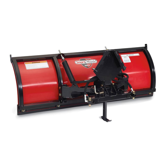
- Page 1 Form No. MSC23351 Rev B Owner's Manual Straight Blade Plow for Groundsmaster ® 3200 or 3300 Series Traction Unit Part No. MSC23345—Serial No. 400000000 and Up Part No. STB13567B—Serial No. 400000000 and Up *MSC23351* B Register at www.bossplow.com. Original Instructions (EN)
-
Page 2: Table Of Contents
This product complies with all relevant European Date directives; for details, please see the separate product Purchased specific Declaration of Conformity (DOC) sheet. Model No. BOSS Products limited consumer warranty and BOSS Products commercial warranty policies are located at Serial No. www.bossplow.com. -
Page 3: Safety
Safety • Turn the vehicle and plow off before filling, servicing, or cleaning it. • Do not climb into or ride on the plow. Improper use or maintenance by the operator or owner can result in injury. To reduce the potential •... -
Page 4: Safety And Instructional Decals
Safety and Instructional Decals Safety decals and instructions are easily visible to the operator and are located near any area of potential danger. Replace any decal that is damaged or missing. decalmsc23037 MSC23037 1. Warning—read the Owner’s Manual. 5. Warning—shut off the engine, remove the key, and read the Owner’s Manual before performing maintenance. -
Page 5: Setup
Removing the Shoulder Bolt from Setup the Lift Arms Note: Determine the left and right sides of the Use the removal tool to remove the shoulder bolt from machine from the normal operating position. the lift arms. Preparing the Machine Remove the Deck from the Machine (if required) Refer to the deck Installation Instructions. -
Page 6: Installing The Required Kits
Installing the Plow on the Remove the hose connection from the fitting in port C1 (Figure Machine Install the clevis pins through the lift arm bushings. g316862 Figure 6 1. Fitting 2. Hose connection Remove the fitting from the manifold. Use a pick to remove the orifice disc from the g317027 Figure 7... -
Page 7: Installing The Push Frame
Installing the Push Frame Loosely secure the 2 mounting brackets to the plow using 2 bolts (5/8 inch) and nuts (Figure 10). g297803 g317028 Figure 10 Figure 8 1. Bolt (5/8 inch) 3. Nut (5/8 inch) 2. Mounting bracket Install the brackets. Loosely secure the push frame to the plow and mounting brackets using 2 bolts (5/8 inch) and nuts... -
Page 8: Installing The Hydraulic Hoses
using 2 washers (1/2 inch) and nylon locknuts (Figure 12). Tighten the nylon locknuts until there is a gap of 0.8 mm (1/32 inch) between the trip spring coils. Installing the Hydraulic Hoses Install the hoses to the manifold as shown in Figure g322158 Figure 11... -
Page 9: Product Overview
Product Overview Push the lower switch, on the side console, up or down to raise or lower the plow. g316207 Figure 14 1. Trip springs 3. Attachment plate 2. Hydraulic hose quick couplers g317814 Figure 16 1. Raise / lower the plow Controls Push the upper switch, on the steering column, left or right to angle the plow. -
Page 10: Operation
Operation Operating the Plow Refer to your machine Operator’s Manual for instructions on operating attachments. Operating Tips • Become familiar with the area you are plowing; hidden obstructions such as curbs and pipes can damage your plow or machine. • Do not let snow accumulate;... -
Page 11: Maintenance
Maintenance Recommended Maintenance Schedule(s) Maintenance Service Maintenance Procedure Interval • Tighten all hardware. After the first 2 hours • Check the hydraulic cylinders. • Check the hydraulic lines and hoses. Before each use or daily • Check all fasteners, pins, retainers, nuts, and bolts. •... -
Page 12: Troubleshooting
Troubleshooting Problem Possible Cause Corrective Action Oil leaks from the hydraulic cylinders. 1. The hose is bad. 1. Check the hose for leaks. Apply thread locking compound to the connection or replace the hose. 2. The cylinder is bad. 2. Replace the cylinder. 3.
Need help?
Do you have a question about the MSC23345 and is the answer not in the manual?
Questions and answers