Table of Contents
Advertisement
Quick Links
Advertisement
Table of Contents

Subscribe to Our Youtube Channel
Related Manuals for Boss Snowplow MSC13960


Summary of Contents for Boss Snowplow MSC13960
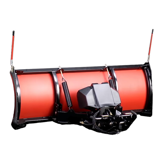
- Page 1 Form No. MSC14781 Rev A Owner's Manual 4ft and 5ft Plow Grandstand ® Multi Force ® Snow Machine or Mower Part No. MSC13960 Part No. STB13567B Part No. MSC14780 Part No. STB13759B *MSC14781* Register at www.bossplow.com. Original Instructions (EN)
-
Page 2: Table Of Contents
Contents Safety ............... 3 Preparation............3 Introduction Operation............3 Safety and Instructional Decals ......3 Whenever you need service, genuine BOSS parts, or Setup ................ 4 additional information, contact an Authorized Service Installing the Trip Stops and Urethane Dealer or BOSS Customer Service and have the Blade............... -
Page 3: Safety
Operation Safety • When transporting the machine, position the plow Improper use or maintenance by the operator or so as not to block your vision. owner can result in injury. To reduce the potential • Do not change the blade position when traveling. for injury, comply with these safety instructions and always pay attention to the safety-alert •... -
Page 4: Setup
Setup Installing the Trip Stops and Urethane Blade Attach the trip stops to the blade using 2 hex-head bolts (5/8–11 x 3 inches) and 2 nylon locknuts (5/8–11 x 3 inches) as shown in Figure g334230 Figure 3 Important: Do not overtighten the bolts and 1. -
Page 5: Mounting The Plow
Mounting the Plow Hook the 2 trip springs through the holes on the push frame (Figure Note: You must first install the Grandstand Low Flow Hydraulic and Quick Attach kits before mounting the plow. Ensure that the plow is sitting upright, with the kickstand lowered (Figure g334232... - Page 6 Moving back and forth between bolts, secure Install the cap on the filler neck. the pin channel in place by torquing the bolts to Repeat steps through until all of the 42 N∙m (31 ft-lb). hydraulic cylinders extend and retract smoothly. Note: Ensure that the pin slides easily in and Note:...
-
Page 7: Product Overview
Product Overview Operation Mounting the Plow Controls Note: You must first install the Grandstand Low Flow Hydraulic and Quick Attach kits before mounting the plow. Ensure that the plow is sitting upright, with the kickstand lowered (Figure 12). g037041 Figure 10 1. -
Page 8: Operating Tips
Disconnect the angle-cylinder hydraulic hoses from the quick disconnect and attach them to each other (Figure 13). g037043 Figure 13 1. Plow hoses 3. Quick disconnects 2. Coupler pin Pull the coupler pin to release the couplers (Figure 13). Start the machine and raise the plow until the kickstand can be lowered all the way. -
Page 9: Maintenance
Maintenance Recommended Maintenance Schedule(s) Maintenance Service Maintenance Procedure Interval • Tighten all hardware. After the first 2 hours • Check the hydraulic cylinders. • Check the hydraulic lines and hoses. • Check the hydraulic-fluid level; refer to your Grandstand Multi Force Operator’s Manual. -
Page 10: Storage
Storage Storing the Plow Drive the plow to your storage location and remove the plow; refer to Removing the Plow (page Grease any exposed metal on the hydraulic cylinders. g334230 Figure 15 Lightly sand and use touch-up paint on painted areas that are scratched, chipped, or rusted. -
Page 11: Troubleshooting
Troubleshooting Problem Possible Cause Corrective Action The plow does not lower. 1. The hydraulic manifold wires are not 1. Check the wires on the hydraulic connected properly. manifold; refer to the hydraulic manifold schematic. 2. The hydraulic valve or L coil is 2. -
Page 12: Schematics
Schematics g037075 Electrical Schematic (Rev. 0) - Page 13 g037128 1. R valve 6. Angle right coil (red) AISE OWER 2. Float coil (blue) 7. Raise coil (orange wire) 3. Lower coil (white) 8. A valve NGLE IGHT 4. Float coil (red and black) 9. Pressure relief valve 5. Angle left coil (green) Hydraulic Manifold (Rev.
- Page 14 Notes:...
- Page 15 Products which have been subject to misuse, negligence, accident, improper installation, maintenance, care, or storage. Products mounted on vehicles other than those listed in the BOSS Snowplow Application Chart and Selection Guide. BOSS Products does not assume liability for damage to your motor vehicle resulting from the attachment or use of any BOSS products. Vehicle risk is the sole responsibility of the purchaser.
- Page 16 Products which have been subject to misuse, negligence, accident, improper installation, maintenance, care, or storage. Products mounted on vehicles other than those listed in the BOSS Snowplow Application Chart and Selection Guide. BOSS Products does not assume liability for damage to your motor vehicle resulting from the attachment or use of any BOSS products. Vehicle risk is the sole responsibility of the purchaser.
Need help?
Do you have a question about the MSC13960 and is the answer not in the manual?
Questions and answers