
Related Manuals for Televes Multimetter FSM 650


Summary of Contents for Televes Multimetter FSM 650
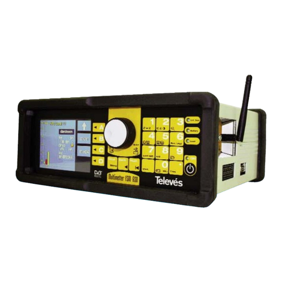
- Page 1 Field Strength Meter Multimetter FSM 650 U s e r M a n u a l Ref.5923 w w w . t e l e v e s . c o m...
-
Page 3: Table Of Contents
Multimetter FSM 650 Ref. 5923 Index .......... - Page 4 Multimetter FSM 650 Ref. 5923 3.3.2.- Equipment configuration ..........
- Page 5 Multimetter FSM 650 Ref. 5923 3.3.3.2.2.4.5.- WLAN ..........
-
Page 6: Installation
Multimetter FSM 650 Ref. 5923 SAFETY MEASURES Before using the equipment, read the user manual and read the section on SAFETY MEASURES. symbol on the equipment indicates: “SEE USER MANUAL”. This manual may also contain the Caution or Warning symbols. -
Page 7: Power Supply
Multimetter FSM 650 Ref. 5923 1.2.- POWER SUPPLY The FSM 650 has two operation modes; external powering or battery powered. 1.2.1.- External powering A DC adapter is provided with the equipment which allows you to connect the equipment to the mains, both for normal operation as well as for charging the batteries. - Page 8 Multimetter FSM 650 Ref. 5923 While the equipment is charging the battery, the Battery (11) LED will flash. In any case, the equipment will stop charging once this is complete. The equipment is constantly monitoring the status of the batteries and it informs the user of their status via an LED icon (Battery (11)) and an audio signal.
-
Page 9: Start-Up
Multimetter FSM 650 Ref. 5923 Note on charging the battery: => Whenever possible, it is advisable to recharge the batteries completely. In other words, when the recharging process begins, do not interrupt it, until the batteries are 100% full. => If you are not going to use the equipment for a while, the battery level should not be very low. -
Page 10: Product Description
The meter includes the possibility of using several types of units: dBµV, dBmV, dBµV/m (calculated for a Televes DAT45 antenna and 10 metres of T100 cable) and dBm. The meter is configured by default to measure in dBµV. - Page 11 Multimetter FSM 650 Ref. 5923 The menu functions are in a hierarchic order, so that they are very easy to find and use. Another important characteristic is that the menu functions are displayed on the 5” coloured TFT screen. Thanks to the OSD function, we can see the images of the tuned channel (or the...
-
Page 12: Specifications
Multimetter FSM 650 Ref. 5923 2.1.- SPECIFICATIONS Next, you can see a list of the main specifications of the FSM 650. Monitor: Screen TFT 5" colour Standard Multistandard: PAL (B, G, D, K, I), SECAM (B, G, D, K, L) - Page 13 Multimetter FSM 650 Ref. 5923 Battery status: An LED, an onscreen icon and a buzzing noise indicating a low battery. External powering connection: Via a DC adapter provided with the FSM. External powering: 12 - 14,8V Maximum consumption: Batteries recharged using provided adapter for car lighter...
- Page 14 Multimetter FSM 650 Ref. 5923 Spectrum representation: Resolution filters: 100 KHz, 250 KHz, 1 MHz and 3 MHz automatically and manually selectable Horizontal span: Terrestrial band: selectable (8, 16, 32, 48, 96, 192, 496 MHz) and Full Span Satellite band: selectable (25, 50, 100, 200, 512 MHz) and Full...
-
Page 15: Element Description
Multimetter FSM 650 Ref. 5923 2.2.- ELEMENT DESCRIPTION The front panel features the following elements: Figure 3.- Front panel (1) Monitor TFT 5" colour screen (2) Short cut buttons Each of these buttons correspond to one of the menu functions that can be seen onscreen at that moment. - Page 16 Multimetter FSM 650 Ref. 5923 (4) Clear/Menu This makes the menu buttons appear and disappear from onscreen. It is also used to close the windows that appear in the middle of the screen (measurement windows, parameter selection windows, etc). (5) Back...
- Page 17 Multimetter FSM 650 Ref. 5923 (9) Freq Selects the frequency tuning mode. If there is a measurement window open and the equipment was previously in the channel tuning mode, when you press the Freq button, the information regarding the tuned channel disappears and the video carrier frequency of that channel appears in its place.
- Page 18 Multimetter FSM 650 Ref. 5923 (24) Switching analyser / TV viewing modes (Button 5) This lets you change from the TV mode to the analyser mode and vice versa. (25) Printing measurements (Button 8) This automatically prints the measurement on an RS-232 printer.
- Page 19 Multimetter FSM 650 Ref. 5923 Side view: 30 31 Figure 5.- The connectors on the side panels (30) RF input Input connector for the signal with an impedance of 75 ohm. (31) Powering Input for the external powering of 12 - 14,8 V...
-
Page 20: How To Use The Product
Multimetter FSM 650 Ref. 5923 3.- HOW TO USE THE PRODUCT 3.1.- THE MENU As explained previously, the different functions of the equipment have been placed in hierarchical order, so that they are very user-friendly. The menu texts appear onscreen, superimposed over the picture, which can be the demodulated picture from the tuned TV channel (TV mode) or the spectrum (analyser mode). - Page 21 Multimetter FSM 650 Ref. 5923 Config. Auto Monitor Language Dsconnect Paramtres Units Scart Informa. Clock Battery Battery Update Change Regenerat. Mode Sel. Audio Channel View Mode Measure Carrier Search (types) Measure Search Sel. Audio Sync. Teletext Digital Analogue Next Prev.
-
Page 22: Tuning Modes
Multimetter FSM 650 Ref. 5923 3.2.- TUNING MODES The FSM 650 has 2 tuning modes: by channel or by frequency. To select one or the other, use the Chan. (channel tuning) and Freq. (frequency tuning). If using the channel tuning option, the measurements taken will be done on the video carrier of that channel. -
Page 23: Measurement Configuration
Multimetter FSM 650 Ref. 5923 3.3.1.- Measurement configuration By using the functions in this menu you can set the parameters that affect the measurements that you are going to take. All of the windows that are opened with the different functions of the “Measurement Configuration”... -
Page 24: 2.1.- Lnb
Multimetter FSM 650 Ref. 5923 Current status of the Options. equipment These are selected by using the rotating knob and Indicates the power that is are activated when this being supplied knob is pressed Indicates if the 22KHz tone is activated... - Page 25 Multimetter FSM 650 Ref. 5923 Current status of the equipment Options. Indicates the power that is being These are selected by supplied to the preamplifiers using the rotating knob and are activated when Indicates if the 22KHz tone is this knob is pressed...
-
Page 26: 2.2.- Diseqc
Multimetter FSM 650 Ref. 5923 3.3.1.2.2. DiSEqC (satellite band only): The Diseqc protocol lets you work with multiswitches that have up to 16 inputs. To do so, when the meter is in the satellite band, you must enable, in the powering menu, the current and tone that corresponds to the desired polarity and satellite band. -
Page 27: 2.3.- Scr
Multimetter FSM 650 Ref. 5923 3.3.1.2.3.- SCR The FSM 650 is capable of controlling devices (LNB, multiswitches) compatible with the SCR protocol defined in the 50494:2006 standard. The basic purpose of this protocol is to divide the FI bandwidth (950MHz to 2150MHz) into user bands or “slots”. The number of wavelengths varies from one application to another, and the maximum is defined in the standard as 8. -
Page 28: 2.4.- Motor Control
Multimetter FSM 650 Ref. 5923 The user may scroll through in FI and the meter will automatically carry out the necessary functions in order to visualise the signal correctly. Figure 14.- SCR channel tuned 3.3.1.2.4. Motor Control The FSM 650 allows users to control the DiSEqC motors used to move mobile parabolic antennas. -
Page 29: 3.- Channels And Standards
Multimetter FSM 650 Ref. 5923 EST: Allows the motor to move EAST. Each time the key is pressed it will correspond to one step in the movement of the motor (step motors). If the key is held down, successive sequences of movements will be performed until the key is released. -
Page 30: 3.2.- Select Plan
Multimetter FSM 650 Ref. 5923 3.3.1.3.2.- Select Plan This selects the channel plan that the user wants to use. The options that will be available with this function will depend on the band that is selected: Terrestrial band: CCIR, STDL, OIRT, CCIR-IT, DAB, SIM.7637, SIM.4009... -
Page 31: 3.3.- Video Invertion
Multimetter FSM 650 Ref. 5923 3.3.1.3.3.- Video invertion This function lets you select if the video signal that comes from a satellite band is inverted (ON) or not (OFF). By default, this option is OFF. It is useful when watching the video of satellites from the C band. -
Page 32: 4.- Memory Logger
Multimetter FSM 650 Ref. 5923 3.3.1.4.- Memory Logger. This section describes how to access a series of functions that let you turn the majority of processes that you carry out with the meter into automatic operations. On screen you will see a window with a list of the meter memories. If no memories have been recorded, the window will be empty. -
Page 33: 4.1.1- Save
Multimetter FSM 650 Ref. 5923 To configure the equipment according to the stored parameters in a specific menu, simply press button (or go to the CONF. MEASURE => MEMORIES LOGGER => MEMORIES menu), select the desired memory from the list and press If there isn't any memory in the meter, the message "NO MEMORIES"... - Page 34 Multimetter FSM 650 Ref. 5923 First free memory. Flashing digits with the On the lower part of lower disposable the window, the number. instructions that the user must follow to Press to save. save the memory appear. Figure 21.- Saving a memory When the user confirms that s/he wants to save the memory, the message "MEMORY SAVED"...
-
Page 35: 4.1.2.- Delete
Multimetter FSM 650 Ref. 5923 3.3.1.4.1.2.- Delete When you want to delete a specific memory, press the DELETE button. Next a new window appears where you can see the list of the available memories. Figure 23.- Deleting memories Use the rotating knob to move through the list. When you find the memory you want to erase, press , and this memory will be highlighted. - Page 36 Multimetter FSM 650 Ref. 5923 have been edited, the process has finished. If the proposed name does not have 6 characters, it will be necessary to fill in the remaining spaces with blanks ("_"). If re-naming a memory that already exists, and if the new name has less characters than the old name, the characters that you wish to erase should be replaced with "_"...
-
Page 37: 4.2.- Macromeasurements
Multimetter FSM 650 Ref. 5923 3.3.1.4.2.- Macromeasurements A MACROMEASUREMENT is a group of a specific number of memories (different measurements), that the meter will be able to execute automatically and add the results to a specific measurement LOG. You can configure up to 100 different MACRO MEASUREMENTS! (automatic measurements with different memories). - Page 38 Multimetter FSM 650 Ref. 5923 When the is pressed, the MACRO OPTIONS menu is displayed. Figure 25.- Macro options Use the rotating knob to choose the different options of this menu: - Run Macro. Starts the execution of the selected Macromeasurement. If the selected macromeasurement does not contain any memory, the meter will display the following message "MACRO EMPTY".
- Page 39 Multimetter FSM 650 Ref. 5923 Figure 27.- Change to satellite connector The other possibility that can be chosen using the button is the Broadband outlet where the equipment carries out the Macromeasurement in both bands with no interruptions. If you press...
- Page 40 Multimetter FSM 650 Ref. 5923 To execute the Macromeasurement again in a new outlet, press again. If you want to finish the Macromeasurement, press any button. Figure 29.- Continue or cancel Macromeasurement - LOG options. This option lets us select the possibility of continuing with a LOG which we had previously created or of starting with a new one, in this case the equipment will suggest a name for the new "LOG"...
- Page 41 Multimetter FSM 650 Ref. 5923 within these limits, a screen will appear showing the number of measurements performed and bearing the message “all measurements correct”. In the event that the measurements fall outside the preset limits, the user will be shown the information on such measurements (value of the measurement and channel information).
-
Page 42: 4.2.1.- New Macro
Multimetter FSM 650 Ref. 5923 3.3.1.4.2.1.- New Macro This option lets us create new Macromeasurements using the memories inside the meter. A window opens and the name of a Macromeasurement appears with the cursor flashing. The name that the equipment proposes to identify each Macromeasurement is: “MAC” and a two- digit number which will be the lowest number available at that time. -
Page 43: 4.2.2.- Edit Macro
Multimetter FSM 650 Ref. 5923 Note: If the meter has any option installed, when we use the SELECT ALL option, if the number of measurements is greater than 250, the meter will display a warning onscreen and it will only select the first 250. This warning will also appear when the user selects the memories manually. -
Page 44: 4.3.- View Data Logs
Multimetter FSM 650 Ref. 5923 3.3.1.4.3.- View DATA LOGS In this section you can see the results of the Macromeasurements that were executed and the results of the SCAN&LOG. The meter will display a window with a list of the DATA LOGS. At the bottom of the window you will see the content of each one. -
Page 45: 4.3.1.- Erase Logs
Multimetter FSM 650 Ref. 5923 3.3.1.4.3.1 3.3.1.4.3.2 3.3.1.4.3.3 Figure 36.- Measurements in each outlet 3.3.1.4.3.1.- Erase LOGS This option lets you erase the selected LOGS. To do this, use the rotating knob to mark the LOGS, selecting them using . The marked registers will appear in yellow, then press the button (CONFIRM) and complete the erasing process by pressing . -
Page 46: 4.3.3.- Scan&Log
Multimetter FSM 650 Ref. 5923 3.3.1.4.3.3.- SCAN&LOG The function SCAN&LOG added into the meter allows the equipment to automatically scan the terrestrial band and carry out the measurements depending on some selectable parameters. This function can automatically identify if a channel is analogue or digital and store the measurements that characterise these channels in a "LOG". - Page 47 Multimetter FSM 650 Ref. 5923 -Digital: this only identifies the COFDM digital channels and carries out the power, C/N, BER and MER. -Analogue + Digital: this identifies both the analogue channels as well as the COFDM digital channels and it will carry out the corresponding measurements.
- Page 48 Multimetter FSM 650 Ref. 5923 The SCAN&LOG shall be carried out within the channel plan that is selected at that moment. If the user wants to carry out a SCAN&LOG in another channel plan, it will be necessary to change it in the equipment’s measurements configuration.
-
Page 49: 4.4.- Graphs
Multimetter FSM 650 Ref. 5923 3.3.1.4.4.- Graphs Function dealing with the graphs in the meter. This function will be available when the meter is in analyser mode. If you try to access this function in another mode, the message "ONLY SPECTRUM"... -
Page 50: 4.4.1.- Save Graphs
Multimetter FSM 650 Ref. 5923 While we are reviewing the graphs, a flashing message will appear onscreen which displays the name of the GLOG and the graph. Using the rotating knob, we can scroll through the graphs in the GLOG. -
Page 51: 4.4.1.1.- Glog Options
Multimetter FSM 650 Ref. 5923 3.3.1.4.4.1.1.- GLOG options These functions let the user modify the location of the new graphs in the new GLOGS, in previously-created GLOGS or modify the name of the current GLOG. 3.3.1.4.4.1.1 3.3.1.4.4.1.2 Figure 44.- GLOG options 3.3.1.4.4.1.2.- Edit Name... -
Page 52: 4.4.3.- Erase Graph
Multimetter FSM 650 Ref. 5923 3.3.1.4.4.2.1 Figure 45.- Editing the name of a graph 3.3.1.4.4.3.- Erase Graph With this function you can erase the GLOGS directly together with all the graphs they contain. It is possible to select 1 or more GLOGs for the erasing process and then press to confirm. -
Page 53: Equipment Configuration
Multimetter FSM 650 Ref. 5923 3.3.2.- Equipment configuration The functions in this menu set all of the parameters that are related to the meter’s configuration. All of the windows that open in the different functions in the “Equipment Configuration” menu can be closed by using the Clear button. -
Page 54: 2.- Automatic Shut-Down
Multimetter FSM 650 Ref. 5923 3.3.2.2.- Automatic shut-down The equipment has the option of automatically turning off once a certain programmable time of inactivity has elapsed. This period of inactivity that can be selected ranges from 1 to 59 minutes. The user can also disable this function (OFF). The equipment has a default value for this period of inactivity of 15 minutes. -
Page 55: 3.1.- Volume
Multimetter FSM 650 Ref. 5923 3.3.2.3.1.- Volume (short cut button Use the rotating knob to increase or decrease the volume. The volume screen appears as follows: Figure 50.- Selection of volume 3.3.2.3.2.- Brightness (short cut button This increases or decreases the brightness of the picture onscreen. It operates in the same way as the volume control. -
Page 56: 5.- Scart
Multimetter FSM 650 Ref. 5923 dBµV: Used for devices with reduced output voltage, below 130 dBµV, such as antenna devices. dBmV: Used for devices with reduced output voltage, particularly to provide input sensitivity data for receivers and in CATV equipment. - Page 57 Multimetter FSM 650 Ref. 5923 Scart auto: Normal operating mode of the scart, in other words, when there is a signal in the scart, it is automatically seen onscreen. It is important to note, however, that this function depends on the device being used, and therefore, it may be that, although a device with a video signal is connected to the scart, this may not appear onscreen.
-
Page 58: 6.- Information About The Equipment
Multimetter FSM 650 Ref. 5923 3.3.2.6.- Information about the equipment When this function is selected, a window will open which will display information about the equipment, as can be seen below: Serial number Model Software version Voltage measured in the battery Figure 53.- Window displaying equipment information... -
Page 59: 6.2.- Changing The Battery
Multimetter FSM 650 Ref. 5923 3.3.2.6.2.- Changing the battery The FSM 650 offers two possibilities when changing the battery: A) A possibility is to change the battery for another with a different capacity. The equipment comes with a Ni-MH 6 AH battery which will provide the equipment with more than 4 hours of battery life. -
Page 60: 6.3.- Battery Regeneration
Multimetter FSM 650 Ref. 5923 Standard battery Ni-MH 3,5 AH Long life battery Ni-MH 6 AH Figure 55.- Configuration of the switches according to the type of battery 4.- Switch the equipment off 5.- Disconnect the equipment from the mains B) Another possibility is to substitute the battery for another with the same characteristics. - Page 61 Multimetter FSM 650 Ref. 5923 other key is pressed, the meter returns to its previous state. Figure 56.- Battery regeneration When the charging process begins, the meter will switch off while the battery light and the ON light will flash on and off.
-
Page 62: 7.- Clock
Multimetter FSM 650 Ref. 5923 3.3.2.7.- Clock The window that appears as follows: Time Date Figure 58.- Clock option It is possible to vary the time (the hour and minutes) and the date (day, month and year). To do so, the user needs to press the rotating knob and the hour (in the time) will appear highlighted (dark blue square). -
Page 63: Tv Mode
Multimetter FSM 650 Ref. 5923 3.3.3.- TV mode (short cut button When this menu is selected, the equipment switches automatically to TV mode, in other words, the user will see the demodulated television signal of the tuned channel onscreen. 3.3.3.1 3.3.3.2... -
Page 64: 1.2.- Synchronism
Multimetter FSM 650 Ref. 5923 Figure 60.- Indication via bars 3.3.3.1.2.- Synchronism This option displays the representation of the synchronism burst on the left-hand side of the screen. If a digital measurement is being carried out (power, C/N, BER, MPEG), it will not be possible to see the synchronism burst, as the meter supposes that the tuned channel is digital and therefore does not represent this burst. -
Page 65: 1.3.- Measurement Windows
Multimetter FSM 650 Ref. 5923 3.3.3.1.3.- Measurements window (short cut button When this option is selected, the window that corresponds to the last measurement that was carried out, opens. In other words, if the last measurement that was carried out was the C/N (for example), the C/N window will open and the C/N measurement will be carried out in the tuned channel. -
Page 66: 1.4.- Teletext
Multimetter FSM 650 Ref. 5923 3.3.3.1.4.- Teletext When this function is selected, the teletext information of the tuned channel will appear onscreen (if the channel does not dispose of this information, NO TTX will appear). The representation level of the teletext function is 1.5 Figure 63.- Teletext window... -
Page 67: 2.1.- Analogue
Multimetter FSM 650 Ref. 5923 3.3.3.2.1 3.3.3.2.2 Figure 64.- Measurement menu 3.3.3.2.1.- Analogue measurements (short cut button The corresponding submenu is as follows: 3.3.3.2.1.1 3.3.3.2.1.2 3.3.3.2.1.3 3.3.3.2.1.4 Figure 65.- Analogue measurements 3.3.3.2.1.1.- Level If the channel tuning mode has been selected, this function will measure the carrier level of the tuned channel. -
Page 68: 2.1.2.- V/A
Multimetter FSM 650 Ref. 5923 Frequency tuning mode: information on the tuned frequency Signal level Figure 66.- Abbreviated form You can vary the frequency by using the rotating knob (in the terrestrial band with a resolution of 50 KHz and in the satellite band 100 KHz), or by using the number pad. -
Page 69: 2.1.3.- Automatic C/N
Multimetter FSM 650 Ref. 5923 V/A measurement Tuned frequency Audio carrier Signal level in the tuned Audio carrier level frequency Figure 69.- V/A measurement. Frequency tuning The tuned frequency is taken as the video carrier, in other words, it is where the video level is measured. - Page 70 Multimetter FSM 650 Ref. 5923 Selected channel plan C/N measurement Tuned channel Channel bandwidth Figure 71.- Automatic C/N measurement. Channel tuning C/N measurement Tuned frequency Channel bandwidth Figure 72.- Automatic C/N measurement. Frequency tuning If in channel tuning mode, you will be able to see the channel with the carrier that is being used to carry out the level measurement.
-
Page 71: 2.1.3.1.- Channel Bw
Multimetter FSM 650 Ref. 5923 3.3.3.2.1.3.1.- Channel BW When this option is pressed, a small window opens on top of the previous window, displaying the value of the video bandwidth which will be taken into account when automatically compensating the noise (we recommend 5 MHz for this measurement). As the user turns the rotating knob, the different options will appear. -
Page 72: 2.1.4.1.- Reference Frequency
Multimetter FSM 650 Ref. 5923 which you want to measure the noise level (reference frequency) and the channel bandwidth. To do so, this function has the following submenu: 3.3.3.2.1.4.1.- Reference frequency By pressing this option, the noise frequency is highlighted in the window (dark background). -
Page 73: 2.2.- Digital
Multimetter FSM 650 Ref. 5923 3.3.3.2.2.- Digital measurements (short cut button When a digital measurement is selected, the image from the TV signal will disappear from the screen, and a warning message will appear that indicates that this is a digital measurement. -
Page 74: 2.2.1.1.- Channel Bw
Multimetter FSM 650 Ref. 5923 To change this parameter, the following submenu appears: 3.3.3.2.2.1.1.- Channel bandwidth If this option is pressed, the value of the bandwidth is selected in the channel power window. You can change this value by using the rotating knob: Channel BW Tuned frequency. - Page 75 Multimetter FSM 650 Ref. 5923 3.3.3.2.2.4.1 3.3.3.2.2.4.3 3.3.3.2.2.4.2 3.3.3.2.2.4.4 3.3.3.2.2.4.4 3.3.3.2.2.4.5 Terrestrial band Satellite band Figure 81.- Options for the BER measurements The window that opens when any of the modulations is selected is the same, however the type of modulation varies:...
-
Page 76: 2.2.4.1.- Cofdm
Multimetter FSM 650 Ref. 5923 3.3.3.2.2.4.1.- COFDM (only terrestrial band) Carry out the BER measurement of the digital terrestria signals with COFDM modulation. The submenu for this type of modulation is the following: 3.3.3.2.2.4.1.1 3.3.3.2.2.4.1.2 3.3.3.2.2.4.1.3 3.3.3.2.2.4.1.4 Figure 83.- COFDM measurements The meter is able to identify DVB-H modulation. - Page 77 Multimetter FSM 650 Ref. 5923 Possible parameters that can be selected using the rotating knob Current parameter values Information on the type of modulation Figure 85.- COFDM parameters When the rotating knob is pressed, the window that corresponds to the selected parameter...
-
Page 78: 2.2.4.1.2.- Advanced Measurements
Multimetter FSM 650 Ref. 5923 Figure 87.- Determining a COFDM offset The parameter window will display the information on the constellation being used in each carrier and the code rate in yellow. 3.3.3.2.2.4.1.2.- Advanced measurements 3.3.3.2.2.4.1.2.1 3.3.3.2.2.4.1.2.2 3.3.3.2.2.4.1.2.3 Figure 88.- Advanced measurements 3.3.3.2.2.4.1.2.1.- Error packets... -
Page 79: 2.2.4.1.2.2.- Impulse Response
Multimetter FSM 650 Ref. 5923 Figure 89.- Error packets This function is very useful when identifying problems in an installation, which a certain measurement at a specific time has not been able to detect. 3.3.3.2.2.4.1.2.2.- Impulse Response (ECHO) The FSM 650 allows users to analyse the response from the COFDM channel and to detect possible problems in the signal quality caused by the reception of signals from different sources. -
Page 80: 2.2.4.1.2.3.- Ber/Pw
Multimetter FSM 650 Ref. 5923 The CBER will also be shown, and to the right will alternate between the MER measurement and an ECHO OUT measurement that represents the value of the echo outside of the guard interval. 3.3.3.2.2.4.1.2.2.1.- Param ECO The parameters allow the units to be changed (Km, µs) and the maximum distance value we... -
Page 81: 2.2.4.1.4.- Mpeg
Multimetter FSM 650 Ref. 5923 3.3.3.2.2.4.1.4.- MPEG By pressing on this option, the MPEG decoding is enabled. The message "STARTING MPEG" will appear and then the search for the available services will begin, with the message "SEARCHING SERV.". If we do not dispose of a COFDM signal, the screen will display “UNLOCK”. - Page 82 Multimetter FSM 650 Ref. 5923 Figure 93.- Channel information Note: It is possible to change service at any moment by using the rotating knob. To change channnel press...
-
Page 83: 2.2.4.2.- Qam
Multimetter FSM 650 Ref. 5923 3.3.3.2.2.4.2.- QAM (only terrestrial band) When this function is selected, the equipment measures the BER of a digital signal with QAM modulation. The information window is identical to the previous one. The submenu for this function is the following: 3.3.3.2.2.4.2.1... -
Page 84: 2.2.4.2.2.- Ber/Pw
Multimetter FSM 650 Ref. 5923 BER parameters Constellation parameters Figure 95.- Parameter options 3.3.3.2.2.4.2.2.- BER/PW This function enables commuting between simultaneous BER/PW and BER/MER viewing. 3.3.3.2.2.4.2.3.- MPEG By enabling this option, the user enters the MPEG decoding mode in a QAM channel. The operation mode is similar to MPEG of COFDM (see 3.3.3.2.2.4.1.4). -
Page 85: 2.2.4.2.4.- Constellation
Multimetter FSM 650 Ref. 5923 3.3.3.2.2.4.2.4.- Constellation This function enables the representing of the QAM constellation. The screen will also show complementary information for evaluating CBER/MER signal quality or BER/PW depending on the simultaneously viewed measurement in the BER QAM window. -
Page 86: 2.2.4.3.- Qpsk
Multimetter FSM 650 Ref. 5923 3.3.3.2.2.4.3.- QPSK (only the satellite band) This function measures the BER of a digital signal with QPSK modulation. The information window is exactly the same as the window for the QAM and COFDM modulations. The submenu is the following: 3.3.3.2.2.4.3.1... -
Page 87: 2.2.4.3.3.- Ber/Pw
Multimetter FSM 650 Ref. 5923 3.3.3.2.2.4.3.3.- BER/PW This function enables commuting between simultaneous BER/PW and BER/MER viewing. It is very important to take into account that the CBER parameter determines quite clearly the quality of the installation. This is why we have simplified the interpretation of this parameter with these colours. -
Page 88: 2.2.4.4.- Dab
Multimetter FSM 650 Ref. 5923 3.3.3.2.2.4.4.- DAB When we enter DAB mode (terrestrial or satellite) the equipment automatically selectes the DAB channel plan. The operation mode is similar to other BER measurements (COFDM, QPSK, or QAM). To access this function press: TV mode =>... -
Page 89: 2.2.4.5.- Wlan
Multimetter FSM 650 Ref. 5923 Figure 101.- DAB service selection To change service, use the rotating knob. To confirm, press Note: In DAB the user will not be able to enter a frequency directly, move in frequency mode or change the channel plan. -
Page 90: 2.2.4.5.2.- Spectrum
Multimetter FSM 650 Ref. 5923 The total number of WLANs will be shown, as well as the following information for each access point: Channel (CH): The channel on which the access point is operating. Power (PW): Power received Encrypted: A padlock icon indicates that the WLAN is password protected SSID: Identification of the WLAN. -
Page 91: 2.2.4.5.3.- Clear
Multimetter FSM 650 Ref. 5923 By turning the rotating knob we can move through the different channels (the current channel selected will be indicated with an arrow above the bar), and by pressing the rotating knob a graph will be shown indicating the access points that operate on the selected channel. -
Page 92: 3.- Channel Search
Multimetter FSM 650 Ref. 5923 3.3.3.3.- Channel search (short cut button The FSM 650 features an automatic channel search function. The search is carried out according to a certain threshold as defined by the user in the Search Level. Channel search is a simplified function of SCAN&LOG. If you want the meter to search, identify and carry out automatic measuring, see paragraph 3.3.1.4.3.3. -
Page 93: 3.1.- Search Level
Multimetter FSM 650 Ref. 5923 3.3.3.3.1.- Search level This parameter defines the threshold that the video carrier must surpass for the equipment to tune a specific channel when carrying out an automatic search. When this function is selected, a window opens onscreen, and the value of the search level can be modified using the rotating knob. -
Page 94: 4.- Nicam
Multimetter FSM 650 Ref. 5923 3.3.3.4.- Nicam This function activates the NICAM mode. This mode presents the BER NICAM measurement, and it also disposes of the audio selection. To select the audio, we must choose the desired channel using the rotating knob and press (OFF, Nicam A, Nicam B). -
Page 95: 6.- Fm Radio
Multimetter FSM 650 Ref. 5923 Figure 108.- Audio carrier To close the window use the Clear button. 3.3.3.6.- FM radio This function lets you tune the radio in modulated frequency. When this function is selected, a window opens onscreen where you can see the frequency and the signal level of this frequency. -
Page 96: Spectrum
Multimetter FSM 650 Ref. 5923 3.3.4.- Spectrum (short cut button If this menu is chosen, the meter passes straight to the spectrum analyzer mode. In this mode you can see the signal spectrum according to the selected span and the tuned frequency. The lower part of the screen (under the spectrum) is used to display the parameters, measurements, etc. -
Page 97: 1.- Reference Level
Multimetter FSM 650 Ref. 5923 The information about the tuned frequency or channel appears at the bottom of the screen. If the equipment is in frequency mode, the central frequency of the spectrum will appear. If we turn the rotating knob, we can change the central frequency, in other words, we move the spectrum to one side or the other. -
Page 98: 2.- Span
Multimetter FSM 650 Ref. 5923 Figure 113.- Reference level 3.3.4.2.- Span This function lets you vary the range of frequencies that is represented by the spectrum. The information for the selection of the parameter is displayed on the lower right-hand part of the screen. -
Page 99: 3.- Measurements
Multimetter FSM 650 Ref. 5923 3.3.4.3.- Measurements The measurements are displayed at the bottom of the screen. While any measurement is being viewed, the tuned frequency can be varied by turning the rotating knob. This means that the measurement can be carried out with different frequencies or channels. -
Page 100: 3.1.3.- Automatic C/N
Multimetter FSM 650 Ref. 5923 Figure 115.- A/V carrier ratio 3.3.4.3.1.3.- Automatic C/N The C/N measurement is also displayed on the lower part of the screen. As is the case with the V/A measurement, the carrier level is measured in the spectrum’s central frequency The equipment selects the frequency that is used to measure the noise. -
Page 101: 3.1.4.1.- Reference Frequency
Multimetter FSM 650 Ref. 5923 parameters are displayed on the lower left-hand part of the screen; the level measurement disappears for a moment, and once the desired value has been selected (by pressing the rotating knob), the level measurement re-appears:... -
Page 102: 3.2.- Digital
Multimetter FSM 650 Ref. 5923 3.3.4.3.2.- Digital 3.3.4.3.2.1.- Channel power The channel power is displayed on the lower left-hand part of the screen. For this measurement, the meter takes the spectrum’s central frequency (the tuned frequency) to be the central frequency of the digital channel. -
Page 103: 3.2.2.- C/N Automática
Multimetter FSM 650 Ref. 5923 3.3.4.3.2.1.1 Figure 119.- Bandwidth of the digital channel 3.3.4.3.2.2.- Automatic C/N The automatic C/N measurement for digital channels is the same as for analogue channels. This function has the following submenu: 3.3.4.3.2.2.1.- Channel bandwidth When this parameter is selected, the information about the channel power measurement disappears and the channel bandwidth appears in its place. -
Page 104: 4.- Markers
Multimetter FSM 650 Ref. 5923 3.3.4.4. Markers The FSM 650 has the possibility of using two markers on the screen. Using the functions of this submenu, you can move them through the whole spectrum to carry out the level measurements in the two marked frequencies. -
Page 105: 5.- Rbw
Multimetter FSM 650 Ref. 5923 Second marker selected Figure 122.- Second marker enabled When the marker is selected, you can move it along the spectrum that is visible onscreen (this will depend on the selected span) by using the rotating knob. -
Page 106: 6.- Hold (On/Off)
Multimetter FSM 650 Ref. 5923 3.3.4.6.- Hold (On/Off) This function represents pulse signals or signals that change quickly. When you select it, a yellow graph will appear which indicates the maximum signal levels at each point. When you select it again, this graph disappears. -
Page 107: Error Warnings
Multimetter FSM 650 Ref. 5923 3.4.- ERROR WARNINGS When the equipment detects an error in any of the modules or components, it warns the user through a series of messages as can be seen below: · NO BAT. : This message appears when the equipment is switched on and no batteries are detected. - Page 108 Multimetter FSM 650 Ref. 5923 · NO POWERING: This message appears when the user tries to charge the batteries and there is no external powering. · SHORT CIRCUIT: This message appears when the equipment detects a shortcircuit in the “F” connector. The equipment will also emit a noise.
-
Page 109: Description Of The Inputs And Outputs
Multimetter FSM 650 Ref. 5923 4.- DESCRIPTION OF THE INPUTS AND OUTPUTS 4.1.- RF INPUT The RF input is through the connector (30) on the side panel. The maximum signal level should never exceed 130 dBµV. This connector is easily replaced when this becomes necessary. -
Page 110: Scart Connector
Multimetter FSM 650 Ref. 5923 4.3.- SCART (DIN EN 50049) Figure 126.- SCART Also known as a PERITEL connector (in compliance with standard NF-C92250). The signals in this connector are as follows: PIN Nº SIGNAL SPECS. PIN Nº SIGNAL SPECS. -
Page 111: Maintenance
Multimetter FSM 650 Ref. 5923 5.- MAINTENANCE 5.1.- REPLACING THE BATTERY The battery should be replaced when its capacity (fully-charged) has diminished considerably. To ensure that the equipment operates correctly, it should be provided by Televés, as it should incorporate the appropriate protective features. - Page 112 Multimetter FSM 650 Ref. 5923 WARNING Avoid any type of shortcircuit between the cables to the battery as this could cause serious damage to the equipment. Note: Remember to dispose of the batteries in the appropriate places provided Ni-MH...
-
Page 113: Cleaning Instructions
Multimetter FSM 650 Ref. 5923 5.2.- CLEANING INSTRUCTIONS WARNING Before cleaning the cover, make sure that the equipment is disconnected. Do not use scented hydrocarbons or chlorinated solvents. These products may harm the materials used for the cover. The cover can be cleaned with a bit of normal cleaning liquid and water, using a soft damp cloth. -
Page 114: Appendix 1.- Batteries
Multimetter FSM 650 Ref. 5923 APPENDIX 1.- Batteríes Below is a list of the safety measures that must be taken into account as regards the batteries: This equipment contains a Ni-MH battery packet. · The charging of the batteries should always be carried out with the batteries located inside the meter and using the DC adapter that is provided with the equipment. -
Page 115: Appendix 2.- Channel Plans
Multimetter FSM 650 Ref. 5923 APPENDIX 2.- Channels Plan CCIR 48,25 E05 175,25 S16 266,25 S29 367,25 471,25 575,25 679,25 783,25 55,25 E06 182,25 S17 273,25 S30 375,25 479,25 583,25 687,25 791,25 62,25 E07 189,25 S18 280,25 S31 383,25 487,25... - Page 116 Multimetter FSM 650 Ref. 5923 The frequencies in this channel plan require the use of a universal LNB AMAZONAS 61.0º W 1518 1192 1305 1385 1056 1222 1382 1225 1185 1329 1386 1058 1262 1382 1209 1155 1345 1425 1090...
- Page 117 Multimetter FSM 650 Ref. 5923 EUTELSAT W2 16.0º E 1207 1275 1358 1427 1721 1932 1962 2049 2103 1212 1296 1376 1428 1742 1909 1963 2050 2111 1218 1303 1382 1434 1763 1917 1968 2056 2113 1222 1306 1384 1442...
- Page 118 Multimetter FSM 650 Ref. 5923 TURKSAT 1C/2A 42.0º E 1205 1331 1742 1129 1179 1292 1408 1990 2064 1212 1339 1748 1134 1182 1292 1415 1995 2080 1218 1346 1800 1139 1188 1305 1422 1999 2088 1220 1355 1804 1143...
-
Page 119: Appendix 3.- Maximum And Minimum Values For Signal Quality
Multimetter FSM 650 Ref. 5923 APPENDIX 3.- Maximum and minimum values for signal quality. PARAMETER UNIT MIN VALUE MAX VALUE Level Terrestrial dBµV Satellite dBµV PW QAM dBµV PW COFDM dBµV PW QPSK dBµV dBµV dBµV Terrestrial Satellite COFDM QPSK... - Page 121 Multimetter FSM 650 Ref. 5923 TECHNICAL ASSISTANCE At the end of the manual, there is a complete list of our closest Technical Assistance points, their telephone numbers and emails which can be used for any request or question. REPAIR SERVICE 1º- In order to facilitate the identification of the failure, use the following table:...
- Page 122 Multimetter FSM 650 Ref. 5923 Label to identify bulk for delivery to the Technical Assistance points.
- Page 123 Multimetter FSM 650 Ref. 5923 GUARANTEE Televés S.A. offers a one year guarantee, beginning from the date of purchase for countries in the EEC. For the batteries and due to the characteristics of this article, the guarantee period is limited to six months.
- Page 124 Multimetter FSM 650 Ref. 5923...
- Page 126 S.op.Viale Liguria 24 20068 Peschiera Borromeo (MI) Italia Tel.: (+39)-0251650604 (RA) Fax: (+39)-0255307363 televes.it@televes.com TELEVES MIDDLE EAST FZE P.O. Box 17199 JEBEL ALI FREE ZONE DUBAI, UNITED ARAB EMIRATES Tel.: 9714 88 343 44 Fax: 9714 88 346 44 televes.me@televes.com Rúa B.
- Page 128 Field Strength Meter Multimetter FSM 650 U s e r M a n u a l Ref.5923 w w w . t e l e v e s . c o m...
Need help?
Do you have a question about the Multimetter FSM 650 and is the answer not in the manual?
Questions and answers