Table of Contents
Advertisement
Quick Links
Advertisement
Table of Contents

Subscribe to Our Youtube Channel
Related Manuals for Televes H45 Compact


Summary of Contents for Televes H45 Compact
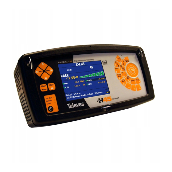
- Page 1 User Manual V.1.0 w w w . t e l e v e s . c o m...
-
Page 3: Table Of Contents
INDEX ............. . PAGE 1.- INSTALLATION . - Page 4 3.3.2.- EQUIPMENT CONFIGURATION ..........3.3.2.1.- LANGUAGE .
- Page 5 3.3.3.2.2.3.- DVB-C ............3.3.3.2.2.3.1.- PARAMETERS .
- Page 6 3.3.5.- OPTICAL INPUT RF ............3.3.5.1.- RF/ÓPTICAL PARAMETERS .
-
Page 7: Installation
1.- INSTALLATION 1.1.- SAFETY RECOMMENDATIONS - The unspecified use of the equipment does not ensure its protection. - If the external DC adaptor is a class I device, for security reasons it should be connected to properly grounded supply lines. - This equipment can be used in Excess Voltage Category II installations and Pollution Degree 2 environments. -
Page 8: Power Supply
1.2.- POWER SUPPLY The H45 has two functioning modes: using external powering and using its battery. 1.2.1.- External powering A DC adaptor is provided with the equipment, enabling its connection to the power grid, both for its operation and battery charging. It is lodged in a special section of the equipment carry case. - Page 9 To restart the process, press the same key again. Charging will also restart if external powering is disconnected and reconnected or if the equipment is turned off. The equipment carries out a continuous monitoring of battery status informing the user of the battery charge through an icon, a LED (Battery) and a sound signal.
- Page 10 If the charging management system detects any condition preventing the initiation of the charging process, the latter will not start. This may occur due to excessive battery temperature, maximum charging time, ... To change the battery, take the following steps: =>...
-
Page 11: Startup
Recommendations on battery charge: => If this can possibly be avoided, it is recommended that the battery not be allowed to discharge completely. => If the equipment is to be stored for a long period of time, it is recommended the battery not be stored at a low charge level. -
Page 12: Features
2.- FEATURES The following is a list of the main features REFERENCE 599020 599022 599023 599021 599024 599025 Languages Spanish, English, French, German, Italian, Portuguese, Polish, Russian Working Bands FM (80 - 110 MHz) Measure and demodulation Terrestrial (47 - 880 MHz) Measure and demodulation DVB-T Measure and demodulation DVB-T2 Measure and demodulation DVB-C... - Page 13 Digital Power (15 - 130 dBµV) C/N Automatic DVB-T CBER (9.9E-2 – 1.0E-6) DVB-T VBER (1.0E-3 – 1.0E-8) DVB-T MER DVB-T Power (40 - 125 dBµV) DVB-T Echos DVB-T Constellation DVB-T MPEG2/MPEG4 DVB-T CAM DVB-T2 Link Margin (-1-10 dB) DVB-T2 LDPCBER (1.0E-2-1.0E-6) DVB-T2 BCHBER DVB-T2 MER DVB-T2 Power...
- Page 14 Programmed Measures Memories Macromeasures Scan&Log Ilog DataLogs Analyzer SPAN Terrestrial: 5, 10, 20, 50, 100, 200, 500 & FULL SPAN Satellite: 5, 10, 20, 50, 100, 200, 500 & FULL RBW Auto based on SPAN Vertical reference level: 5, 10 dB Real time sweep speed <250 ms Screen refresing speed <250 ms Maximum/Minimum...
-
Page 15: Meter Components Description
2.1.- METER COMPONENTS DESCRIPTION On the front panel we have the following components: 13 14 - Front panel - (1) Monitor 5" color TFT screen (2) Numerical keyboard and quick keys. The numerical keyboard permits the introduction of the numerical values required (frequency, channel, symbol rate values, ...). - Page 16 - Numerical keyboard - (rotating selector) Depending on what part of the menu we are in, it will have one function or another. For example, if we have opened a parameter selection window, it will allow us to switch to select our option of choice.
- Page 17 pressing the key , the tuned channel information will disappear, showing in its stead the video carrying frequency for that channel if it is in analog mode, or the central channel frequency, if it is in digital mode. Once the equipment is in frequency tuning mode, if we press this key again, the tuned frequency will be erased, allowing us to introduce the frequency we want to tune in on, using the numerical keyboard.
- Page 18 (Load): Indicates if the equipment is powering external devices. It is the only red LED with the intention of warning the installer of this situation. (ON): Indicates whether the equipment is on. (A): Indicates the equipment is in analog mode (analog measures and de-modulation).
- Page 19 (20) Key SHORT PRESS: TV MODE: Allows one to modify the OSD type that appears on screen. LONG PRESS (Press and hold the key): TV MODE: In digital terms, it switches between BER visualization and MPEG. (21) Key SHORT PRESS: GENERAL: Switches between satellite and terrestrial.
- Page 20 (24) Key SHORT PRESS: GENERAL: Opens up the memory listing for the meter. Direct access to Macro- measurements, Data logs, ILOGS. LONG PRESS (Press and hold the key): GENERAL: Direct access to SCANLOG. (25) Key SHORT PRESS: TV MODE: Next channel search. ANALYZER: Satellite identification.
- Page 21 (28) Key SHORT PRESS: GENERAL: Preamplifier power. Access to Extra Burst, Diseqc, SCR. (29) Key SHORT PRESS: GENERAL: Energy Management. LONG PRESS (Press and hold the key): GENERAL: Start or stop battery charging. Providing external power is connected to the equipment, battery charging will take place. If we interrupt the battery charging process by pressing the following key for more than 3 seconds , the battery charge will not reinitiate until we again press the same...
- Page 22 At the top we have the following items: - Connectors panel - (30) Reset button This enables the restarting of the equipment in the case of malfunction. When the equipment is reset it acquires the status it had the last time it was shut down normally. To activate this button, a non-piercing object must be used at adequate pressure.
- Page 23 (37) Loudspeaker (38) Power External input power 12 – 14.8 V. (39) USB port Connection to PC to use the HSuite program and/or meter software updating. On the sides we have: (40) Ventilators They maintain the optimal functioning temperature for the equipment.
-
Page 24: Product Handling
3.- PRODUCT HANDLING 3.1.- THE MENU As was said before, the different equipment functions are organized into a hierarchy of menus, making their browsing as easy and intuitive as possible. The menu texts appear on screen, over the background image, which may be the demodulated image of the TV channel tuned in mode), the spectrum (analyzer... - Page 25 - Menu statuses - To advance to the next level in the menu hierarchy (providing there is a next level) or execute the selected function, you may use the key . In this case, if a higher level exists, the menu function will be selected.
- Page 26 MENU EXTRA BURST DISEQC SLOT ON SLOT OFF CHANGE BAND FREQ. SLOT LNB AND PREAMP. NORM CHANNELS/NORMS SELECT PLAN MEASURES AUDIO CARRIER RETRIEVE MEASURES PARAM. CONFIG. SAVE QUALITY PROFILES DELETE MEMORIES MEMORIES/LOGGER EDIT NAME MACROS POSITION. ANTENNA DATALOGS CREATE DELETE EDIT NAME EDIT MACRO DELETE LOGS...
-
Page 27: Tuning Modes
3.2.- TUNING MODES The H45 has two tuning modes: by channel, or by frequency. To select one or the other use keys (channel tuning) and (frequency tuning). If you are using channel tuning, the analog measures that are carried out will be made on the video carrier of that channel. - Page 28 (50 KHz variations). If we once again press the key , the frequency information will disappear, and then we can introduce the frequency using the numerical keyboard confirm the frequency by pressing Within the satellite band, and in the frequency tuning mode, if we carry out prolonged depression of the key we will alternate between Real Frequency and FI.
-
Page 29: Functions
3.3.- FUNCTIONS This section explains all the meter functions in detail. The main menu provides the following options: 3.3.1.- Configuration of Measurements Using the functions of this block, the parameters affecting the measurements to be made can be established. All the windows that open for the different functions of the menu "Measurement Configuration"... -
Page 30: 2.- Lnb And Preamplifiers
band is selected, the icon is a parabolic aerial. If the FM radio is selected, the symbol shown is a musical note. - Band change - short pressure on the key , alternates between the terrestrial and satellite bands, while a long pressure on key , enables commuting between the terrestrial, satellite and FM radio bands. - Page 31 Terrestrial band Satellite band - Preamplifiers power - The power for terrestrial band are: OFF, 5V, 13V, and 24V. If, contrarily, the satellite band has been selected, the installer can select the power and the tone of the LNB, and the following sub-menu will appear. At the bottom of the previous window, the band (high or low) and the polarization (vertical or horizontal) corresponding to the power and tone selected are indicated: 5V / 100mA...
-
Page 32: 2.2.- Extra Burst
=> The equipment detects voltage in the coaxial cable. In this case, the message that will appear is "Vext". This situation should be avoided. => When the equipment detects a short circuit, it emits a sound signal, and the message appearing in this case is "Short Circuit". - Page 33 of four, identifying each group of polarities as SAT B ..). For the purpose, within the main menu "Measurement Configuration" and also within "LNB and pre-amplifiers" we will enter the DiSEqC section. The following window will appear: - Satellite selection in the Multi-switch - We will choose the right satellite (An 8+1 input multi-switch will only offer satellites A and B).
-
Page 34: 2.4.- Scr
3.3.1.2.4.- SCR H45 allows one to control those satellite devices that use the SCR protocol, according to the EN 50494:2006 With the "SLOT ON"-button and whenever we are in SATELLITE-Mode and feeding LNB - otherwise the equipment will inform us with the appropriate error messages- “Only Satellite”... - Page 35 The frequencies corresponding to each of these channels are defined by the standard 50494:2006 Channel SCR0 SCR1 SCR2 SCR3 SCR4 SCR5 SCR6 SCR7 Frequency (MHz) 1680 1420 2040 1210 1680 1420 2040 1210 When this mode is activated, an indicator appears in the upper right corner with the flashing SCR indicator.
-
Page 36: 3.- Channels / Standard
3.3.1.3.- Channels and Standards 3.3.1.3.1.- Standard This enables the selection of the color standard. The available standards are the following: B/G, D/K, SECAM B/G, SECAM L SECAM D/K. The following window is viewed on selecting this function: - Standard selection - 3.3.1.3.2.- Selecting a Plan This selects the channel plan that the user chooses. -
Page 37: 3.3.- Audio Carrier
Terrestrial band Satellite band - Channel plans - On selecting a satellite plan, a list will unfold allowing the selection of the desired band and polarity (VL, HL, VH, and ALL). The option includes all the channels of both bands, and both polarizations, ordered by frequency. - Page 38 If we select Other, the sound carrier selection window will close and a window will open in which the user can select another frequency comprised within “4,00” and “9,00” by using the - Audio carrier - To close this window, use the key You may only select Audio Carrier Terrestrial Analog...
-
Page 39: 4.- Measure Parameters
3.3.1.4.- Measure Parameters This function enables the configuration of some of the equipment’s parameters. To browse options use keys . It is also possible to use the following keys . To leave the parameter configuration press - Measure parameters - The different parameters to be configured are the following: - Satellite Frequency It determines the desired frequency, which may be Intermediate Frequency (IF) or Real... - Page 40 - PreAmp This enables the configuration of the input Amplifier stage of the equipment. At this stage we can choose if we want automatic starting or stopping of the equipment (AUTO) or whether it should be permanently stopped (OFF). When the option is in AUTO and the meter considers it necessary to start up the stage, it will show that it is active with...
-
Page 41: 5.- Quality Profiles
- Units The equipment offers the possibility of using several types of units: dBµV, dBmV dBm . The meter is configured by default to measure in dBµV. dBµV: This is used for devices with reduced output voltage, under 130 dBµV, such as aerial devices. -
Page 42: 6.- Logger Memories
3.3.1.6.- LOGGER Memories Within this section we can access a series of functions enabling the automation of most of the processes carried out with the meter. - LOGGER Memories - These functions are: 3.3.1.6.1.- Memories MEMORY enables the saving and recuperation of equipment configurations. The H45 enables the saving of up to 250/1000 different configurations (memories) according to equipment version for your equipment, that you may easily recuperate. -
Page 43: 6.1.1.- Recuperation
To configure the equipment according to the parameters stored in any given memory, you need only press quick key (or browse through the menus up to function MEMORIES) and select the desired memory list and press button or press the menu button RECUPERATE. In the event that no memory exists in the meter, the following message will be seen on screen "WITHOUT MEMORIES". - Page 44 - Recording a memory - Once the saving of a memory is confirmed, the following message will appear on screen "MEMORY RECORDED". The maximum number of memories that can be stored by the meter is 250/1000, according to the equipment version. In the event the memory is completed, the screen will show the message "MEMORIES FULL".
-
Page 45: 6.1.3.- Erase
3.3.1.6.1.3.- Erase When you wish to erase a given memory, press option ERASE. A new window will appear displaying a list of the available memories. - Erase memories - Using browse through the list. When you find one of the memories to be erased, press , and this memory will be highlighted. -
Page 46: 6.1.4.- Edit Name
3.3.1.6.1.4.- Editing memory name With this function the user can modify the name of any memory, whether it is already saved or it is a new one he/she wishes to save. - Editing memory name - If it is a memory that is already on the list, press the option EDIT NAME and then, using the , select from the list the memory whose name you wish to change. -
Page 47: 6.2.- Macromeasures
the action by merely turning , which will annul the new name and restart the process. A name composed entirely of blank spaces is not accepted either. In this case the meter will display an “incorrect name” message. On confirming the memory name change, the following message will appear on screen "MEMORY EDITED". -
Page 48: 6.2.1.- Executing Macromeasures
If we have Macromeasures on the meter, we will use the to browse through the list, and then press “Execute” or key 3.3.1.6.2.1.- Executing Macromeasures This function is used to enable the Macromeasure to run through all the associated memories and record the results on a LOG. - Page 49 - Macromeasure Options - The Parameters to be configured: - Outlet: There are three options. The equipment establishes an order for the execution of the Macromeasure, stopping at the chosen option. - Wide band: The Macromeasure executes all its associated memories. - Ter/Sat: The Macromeasure first executes the terrestrial memory and then the satellite memory.
-
Page 50: 6.2.2.- Creating Macromeasures
- Executing a Macromeasure - 3.3.1.6.2.2.- Creating Macromeasures This function is used to create new Macromeasures from the meter memories. The meter can store up to 100 lists (Macromeasures) of different memories, which can include up to 250 memories each. When we press function "Create"... -
Page 51: 6.2.3.- Erasing Macromeasures
On pressing key a list appears with all the memories stored in the meter. Using the we can browse through the different memories. To associate a Memory to a Macromeasure, we can press key . The Memory we mark will be shown in yellow. -
Page 52: 6.3.- Datalogs
3.3.1.6.3.- DATALOGS In this section you can see the results of the Macromeasures executed and the results of the SCAN&LOG. The meter will show a window with a list of DATALOGS. At the bottom of the window, the contents of each will be shown. - DATALOGS - DATALOGS are the measures that the meter has saved when carrying out one of the... -
Page 53: 6.3.1.- Erasing Datalogs
By using the we can move through the list of DATALOGS. Once we have selected our DATALOG of interest, by pressing the button we can access the results it has stored. The data are displayed on a two-column table that shows on the left the sockets measured, and on the right the results for each socket. -
Page 54: 6.3.3.- Scan&Log
we can move through the list of characters. 3.3.1.6.3.3.- SCAN&LOG The serial SCAN&LOG function that is incorporated in the meter automates the equipment to scan the terrestrial and satellite bands and carry out measurements as a function of selectable parameters. - SCAN&LOG - This function enables the automatic identification of the analog or digital nature of a channel, in the satellite band if we are analysing a DVB-S2 or DVB-S channel and carryout the necessary... - Page 55 - Terrestrial - BER DVB-T/T2 (DVB-T2 only 599021, 599024, 599025) - DVB-S - DVB-S2 When a Terrestrial scan is taking place the BER DVB-T/T2 (DVB-T2 only 599021, 599024, 599025) option can be on. In this case as well as the Power and C/N parameters it also measures the corresponding BER parameters.
-
Page 56: 6.3.4.- Instant Log
- Progress of a SCAN&LOG - To cancel the search, we press the key and a message of confirmation will appear. When we press button SCAN&LOG ends, and pressing any other button will restart it. Once the SCAN&LOG is over, we will be shown a listing of the channels found and the measurements on those channels. -
Page 57: 7.- Positioning Antennas
3.3.1.7.- Positioning antennas When this menu button is selected, it gives you the option of enabling (ON) disabling (OFF) the aerial directing function. This function has been designed to give the installer a reference in regard to signal reception quality, at the moment of directing an aerial, without his needing to view the data shown on the equipment screen. -
Page 58: Equipment Configuration
3.3.2.- Equipment Configuration This option enables access to equipment configuration functions. 3.3.2.1.- Language The H45 gives you the ability to select menu language. The languages available are: Spanish, English, Portuguese, French, German, Italian, Polish and Russian. The following window opens when you select this menu. - Selection of available menu languages - 3.3.2.2.- Energy Options In this menu one has various functions for managing the H45 meter´s energy. -
Page 59: 2.1.- Energy Management
3.3.2.2.1.- Energy Management With this function one can select from three different unit operating modes. The three possible modes are: Normal: The meter´s standard operating mode. Energy-saver: In this mode and using the information offered by the light sensor, the brightness of the screen backlight is reduced and various electronic parameters are adjusted, which increase battery life. -
Page 60: 3.- Monitor Parameters
- Disconnecting time - When the user-programmed disconnecting time has gone by with the equipment inactive, a message will appear on screen reading Automat. Disconnect. along with a progress bar and a sound signal indicating that the equipment is about to turn off. When the progress bar achieves 100%, the equipment will turn off. -
Page 61: 3.1.- Volume
3.3.2.3.1.- Volume. Quick key Using you may raise or lower the volume. The screen looks like this: - Volume - With button the adjustment window is closed. By once again pressing key parameter changes. 3.3.2.3.2.- Brightness. Quick Key This increases or reduces the brightness of the image on screen. It works in a similar way to the volume control. -
Page 62: 3.5.- High Visivility
3.3.2.3.5.- High visivility. Quick Key This function configures the meter to improve viewing of the display in strongly illuminated environments. 3.3.2.4.- Rotating selector This function allows users to adjust the sensitivity of the rotating selector on the device. 3.3.2.5.- Clock The following window opens: - Clock option - This sets time (hour and minutes) and date (day of the month, month and year). -
Page 63: 6.- Video In/Out
3.3.2.6.- IN/OUT Video Select the Input / Output video configuration: - IN/OUT video options - The different options are listed below: Video input: Off: Disables the video input Mini-DIN. On: Enables the video input Mini-DIN. Video output: CVBS: Enables video output Mini-DIN connector LCD: Optimal operation mode LCD and HDMI connector brings out the video with a resolution of 640x480@60Hz. -
Page 64: 7.- Osd Style
=> In the event there is a signal in the Mini-DIN, and it is being displayed on the screen (input mode ON), the meter will continue functioning normally in regard to measurements. This means that the measurements that will be made are those corresponding to the input signal of the “F”... -
Page 65: 8.- Equipment Information
- Select OSD style - 3.3.2.8.- Equipment information When you select this function, a window will open showing equipment information, as shown below: Model Serial Number - Equipment Information Window - 3.3.2.8.1.- Updating Using this option we can upload the license number, enabling an option package. Equipment Config. -
Page 66: 8.2.- Battery Replacement
3.3.2.8.2.- Battery replacement When the installer wishes to change batteries, it will be necessary to inform the equipment of the change so that it can adapt the charging and discharging algorithm of the battery to optimize its autonomy and lifespan. The following are the steps which must be followed when replacing batteries: 1.- Replace the battery following the instructions in section 5.1. -
Page 67: 8.3.- Extended Information
Precautions to be taken when replacing battery: • Both when removing the battery from the equipment and when reconnecting it, make sure that the meter is turned off. • If the battery is removed from the equipment, when it is replaced, make sure that it is properly reconnected. - Page 68 To confirm the change, you must press the key , if any other key is pressed instead, the change will be cancelled. Mode...
-
Page 69: Tv Mode
3.3.3.- Television Mode When this menu is selected, the mode changes automatically to TV. If the meter is in analog mode, the demodulated TV signal of the tuned channel will be displayed on screen if we are in the terrestrial mode. The analog signals of the satellite band will not be demodulated. - Page 70 - Syncronism - Mode...
-
Page 71: 1.2.- Combo Mode
3.3.3.1.2.- Combo (Television - Spectrum) Using this mode, we can view the television image, the spectrum and the measures on any given channel at the same time. The meter screen is divided into two sides: on the left side we can see the TV image, and on the right we can see the spectrum and measures on the channel. -
Page 72: 1.3.- Teletext
The key is a quick key that we can use to browse through the different modes in a circular way ==> Analyzer ==> Combo), and if we maintain pressure on the this we will run through the modes in reverse order. If we are in DVB-T, DVB-S or terrestrial Analog, by using the key we can find the following or the previous channel. -
Page 73: 2.- Measures
3.3.3.2.- Measures From this menu, we access the different measures of the meter. When we select a given measure, a window will open showing the measurement that has been carried out and the frequency (or the channel) on which the measurement was made, corresponding to the frequency (or the channel) that the user had tuned into. -
Page 74: 2.1.- Analogs
3.3.3.2.1.- Analogs The respective sub-menu is shown below: - Analog Measure Options - The measure window is shown superimposed over the demodulated image. On the terrestrial band using , we can alternate between the extended window, the abbreviated window and no window (image only). The extended window contains the following information: - Name of the measure selected - Value of the measurement... -
Page 75: 2.1.1- Level
- Yellow bar: acceptable quality, but recommending improvement - Red bar: bad quality The abbreviated window (only terrestrial band), which only contains: - Frequency or channel on which the measurement is being made - Name of the measure selected - Value of the measurement We can change the main measure of each window by using cursors (the cursors are enabled when the menu is hidden). -
Page 76: 2.1.2.- V/A
3.3.3.2.1.2- V/A (only terrestrial band) The tuned frequency is that taken as video carrier, i.e., that on which the video level is measured. The audio carrier level is taken as many MHz over the value as instructed in the Audio information appearing on screen (5.50 in the example). Pressure on key highlights the tuned frequency information. -
Page 77: 2.1.3- C/N
3.3.3.2.1.3- C/N On selecting this function, the Carrier/Noise ratio measurement will be selected. Noise measurement is carried out automatically. - C/N Measurement. Channel tuning - If the channel tuning mode is used, the channel on whose carrier the level measurement is being taken will appear. -
Page 78: 2.1.4.1.- Line Cnline
3.3.3.2.1.4.1.- Line C/N line This function allows one to change the line with which one synchronises the meter to, in order to carry out the C/N line measurement. Use the to switch between line 3 and line 25 and confirm by pressing the key. - Page 79 (antenna) up to the measuring equipment (prior, cable ...). For the H45, this unit is calculated for a Televes DAT-HD antenna and 10 meters of cable T100 (for more information, please visit http://www.televes.com).
-
Page 80: 2.2.- Digital
3.3.3.2.2.- Digitals The same window opens when any of the modulations is selected, but what varies is the heading giving the modulation type and the kinds of measures shown for each type of modulation: Channel tuned Selected Measure Measurem. Available services - Digital Measures window - Any of the available measures can be selected to be viewed on a larger scale than the rest. -
Page 81: 2.2.1.- Dvb-T
3.3.3.2.2.1.- DVB-T On selecting this function, the equipment will carry out the measures corresponding to a DVB-T digital signal. The corresponding sub-menu for this type of modulation is as follows: - DVB-T Measures - The available measures for a DVB-T signal are: Power, C/N, CBER, VBER and MER. - Page 82 When the AUTO option is selected in any of the parameters, the equipment automatically selects the suitable option even though hookup time will increase. The following is an example of the parameter selection window: Possible Current parameters to be parameter selected with the values.
-
Page 83: 2.2.1.2.- Ber
3.3.3.2.2.1.2.- BER This function enables you to return to the BER measures window from another window. 3.3.3.2.2.1.3.- MPEG Pressing this option when we have a DVB-T signal will enable MPEG decoding. The messages “Initiating MPEG” , “Tuning MPEG” will appear, and then the search for available services will start, the message “Searching Serv...”... - Page 84 - Extended Information - In the event that no DVB-T signal is available, the information windows will show “UNLOCK”. MPEG4 DVB-T. The MPEG4 services decryption is possible in the H45 (some options). The H45 technology allows to display the services up to 1080p being them compatible with the following digital audio standards: AAC, EAAC and AC3.
- Page 85 - MPEG4 Decoding - CAM (Conditional-access module) DVB-T. The H45 meter has a Common Interface slot (CI) in its higher part where a Conditional Access Module (CAM) is inserted. It is valid for any digital modulation always being compatible with DVB-CI and MPEG-2 and MPEG4 services.
-
Page 86: 2.2.1.4.- Constellation
- CI module introduction - 3.3.3.2.2.1.4.- Constellation This function represents the DVB-T constellation of all the carriers: the TPS carriers plus the disperse carriers, or of a specific selected carrier. As well as this graphic representation, the same screen shows the CBER measures of the DVB-T... -
Page 87: 2.2.1.4.1.- Zoom
3.3.3.2.2.1.4.1.- Zoom Using this option, a quadrant of the constellation to be represented may be selected for more detailed viewing. When you select “Zoom OFF”, the on-screen graphic will expand to the four quadrants. - DVB-T Constellation Zoom - 3.3.3.2.2.1.4.2.- Carrier DVB-T transmission of any channel is composed of some 8,000 carriers, of which there are 6,817 usable ones, and they are divided into signal and data carriers. -
Page 88: 2.2.1.5.- Echoes
3.3.3.2.2.1.5.- ECHOES ECHOES option makes it possible to visualise the time response of the DVB-T channel. This function is very useful to find out if the signal we are receiving comes from a single main beam or if a series of secondary beams have been added with different delays and bandwidths. This will often help to explain why the BER does not have an acceptable value if we have a good C/N and signal level. -
Page 89: Dvbt-2
3.3.3.2.2.2.- DVBT-2 (599021, 599024, 599025) With this option, when the DVB-T/T2 mode is selected, the device automatically analyses the digital terrestrial signal and detects the signal type. If it is a DVB-T signal, the meter will activate the DVB-T functions. If it detects a DVB-T2 signal, the main measurement will be LinkMargin, Power, C/N, LDPCBER, BCHBER and MER. -
Page 90: 2.2.2.2.- Ber
- DVB-T2 Parameters - 3.3.3.2.2.2.2.-BER (599021, 599024, 599025) Option Use this feature to go back to the BER measurement window from other windows. - BER Mode - Mode... -
Page 91: 2.2.2.3.- Mpeg
3.3.3.2.2.2.3.- MPEG (599021, 599024, 599025) Clicking on this option when the DVB-T2 signal is available will activate MPEG decoding. When this option is selected, MPEG2 and MPEG4 services can be decoded. H45 technology enables you to get services of up to 1080p and is compatible with audio standards: AAC, EAAC and AC3. -
Page 92: 2.2.2.4.- Constellation
3.3.3.2.2.2.4.- Constellation (599021, 599024, 599025) This feature represents constellation DVB-T2. Along with this graphical representation, the calculated LDPCBER and MER measurements are also displayed on the same screen. - DVB-T2 Constellation - 3.3.3.2.2.2.4.1.- Zoom (599021, 599024, 599025) Use this option to select the quadrant for the constellation to be displayed for a detailed view. If you select “Zoom OFF”, the on-screen graph will cover all four quadrants. -
Page 93: 2.2.3.- Dvb-C
3.3.3.2.2.3.- DVB-C On selecting this function, the equipment makes the measurements corresponding to a digital DVB-C signal. The information window is identical to that of DVB-T measures. The following is the sub-menu corresponding to this function: - DVB-C Measures - The measures available for a DVB-C signal are:... -
Page 94: 2.2.3.2.- Ber
3.3.3.2.2.3.2.- BER This function enables the viewing again of the BER measure window from another window. 3.3.3.2.2.3.3.- MPEG Pressing this option when we have a DVB-C signal will enable MPEG decoding. The messages “Initiating MPEG”, and “Tuning MPEG” will appear, and then the search for available services will start, the message “Searching Serv...”... - Page 95 MPEG4 DVB-C. It works similarly to the MPEG-4 DVB-T section. - MPEG4 Decoding - CAM (Conditional-access module) DVB-C It works similarly to the CAM DVB-T section. Mode...
-
Page 96: 2.2.3.4.- Constellation
3.3.3.2.2.3.4.- Constellation This function represents the DVB-C signal constellation. As well as showing this graphic representation, the screen shows the CBER of the DVB-C signal. - DVB-C Constellation - 3.3.3.2.2.3.4.1.- Zoom Using this option, a quadrant of the constellation to be represented may be selected for more detailed viewing. -
Page 97: 2.2.4.- Dvb-S
3.3.3.2.2.4.- DVB-S This function carries out the measurements of a digital DVB-S signal. The information window is identical to that of the DVB-C and DVB-T. The following sub-menu appears on selecting this function: - DVB-S measures - The measures available for a DVB-S are: Power, C/N, CBER, VBER and... -
Page 98: 2.2.4.2.- Ber
3.3.3.2.2.4.2.- BER This function enables the viewing again of the BER measure window from another window. 3.3.3.2.2.4.3.- MPEG Pressing this option when we have a DVB-S signal will enable MPEG decoding. The messages “Initiating MPEG”, and “Tuning MPEG” will appear, and then the search for available services will start, the message “Searching Serv...”... - Page 99 MPEG4 DVB-S It works similarly to the MPEG-4 DVB-T section. - MPEG4 Decoding - CAM (Conditional-access module) DVB-S It works similarly to the CAM DVB-T section. Mode...
-
Page 100: Dvb-S2
3.3.3.2.2.5.- DVB-S2 Option This functionality enables the obtaining of quality measurements of a DVB-S2 signal. The information window is identical to that of the measures DVB-S, DVB-C and DVB-T. The following sub-menu appears on selecting this function: - DVB-S2 Measures - The measure used for evaluating signal quality is Link Margin (dB), that indicates how “far... -
Page 101: 2.2.5.2.- Ber
- DVB-S2 Parameter Options - 3.3.3.2.2.5.2.- BER This function enables the viewing again of the BER measure window from another window. 3.3.3.2.2.5.3.- MPEG Clicking on this option when we have a DVB-S2 signal, MPEG2 services will be displayed at standard resolution or up to 1080p of MPEG services (599201, 599001 or 5997). You will see the messages "Initiating MPEG",... - Page 102 In the extended information windows, the network identifier is also shown (if available), the number of supplier services and other different items of data on the tuned channel in each of the two windows. On the first of the windows these data are: SID, VPID (for audio channels, value 0 will be shown),...
-
Page 103: 2.2.5.4.- Constellation
3.3.3.2.2.5.4.- Constellation This function represents the constellation of the DVB-S2 signal. As well as this graphic representation, the same screen shows the Link Margin measures of the DVB-S2 signal. - DVB-S2 Constellation - 3.3.3.2.2.5.4.1.- Zoom Using this option, a quadrant of the constellation to be represented may be selected for more detailed viewing. -
Page 104: 2.3.- Auto A/D
3.3.3.2.3.- A/D AUTO This function of the H45 meter makes it possible to automatically identify the type of channel: analogue or digital. AUTO A/D function is only available for the TV mode and Combo mode. This mode may also be accessed quickly by holding down the key for more than 1 second. -
Page 105: 3.- Channel Search
3.3.3.3.- Channel search The H45 incorporates the automatic channel search function. Channel Search is a simplified function of the SCAN&LOG. If you wish the meter to search for channels, identify them and carry out measuring automatically, consult the SCAN&LOG section. The search for terrestrial channels will always be carried out based on the channel plan that we have selected. -
Page 106: Analyzer Mode
3.3.4.- Analyzer If this menu is chosen, you will automatically go to the spectrum analyzer mode. In this mode you will see the signal spectrum according to the selected span and the tuned frequency. The lower part of the screen (under the spectrum) is used to show the measures, parameters, etc. The menu texts are hidden by default, with the purpose of complete spectrum viewing. -
Page 107: 1.- Reference Level
The tuned channel or frequency information appears in the middle of the bottom part of the screen. If the equipment is in frequency mode, the central frequency of the spectrum will appear. Using , we will go varying the central frequency of the spectrum, i.e., displacing the spectrum to one side or the other. - Page 108 - Mode AUTO - When this function is pressed, the main measure momentarily disappears, and in its place the reference level options appear, which may be changed by using the or the keys, until we confirm by using key Thereupon, the information on the reference level disappears, and the information on the selected level reappears.
- Page 109 A quick way of changing the reference level is by using keys when the menu is hidden. thus the reference level may be quickly changed to adapt it to the current signal. When the input signal level is excessive for the selected reference level, this is shown when the numbers indicating the level of each horizontal division are in red.
-
Page 110: 2.- Span
3.3.4.2.- Span Using this function one can vary the range of frequencies represented in the spectrum. The information for selecting this parameter appears at the lower right of the screen. Just as in the previous case, the information on the selected measure disappears momentarily, being replaced with the information on the span. -
Page 111: 3.- Measures
3.3.4.3.- Measures In the H45, the measures are viewed on the lower part of the screen. At the bottom left of the screen all the measures are shown, i.e., Level, V/A and CN for analog terrestrial channels, Level and C/N for analog satellite channels, or Power and C/N for digital channels. At the bottom right of the screen, the main measure selected will be displayed in large-sized characters to ease reading when the user is at a distance from the equipment. -
Page 112: 3.1.2.- V/A
3.3.4.3.1.2.- V/A When you select this function, you choose the measurement of the Video Carrier Level / Audio Carrier Level ratio as a main measure. The central frequency of the spectrum is taken as the video carrier frequency, and the frequency indicated in the audio carrier selection is taken as that of the audio carrier (this function is in Config. -
Page 113: 3.1.4.- Field Streng
3.3.4.3.1.4.- Field Strength Operation similar to paragraph 3.3.3.2.1.5 field strength. 3.3.4.3.1.5.- Bandwidth This parameter is necessary for the proper measurement of the C/N, since it will be used to correct the value of the noise level measured, so as to reference it to the whole bandwidth of the channel. -
Page 114: 3.2.- Digital
3.3.4.3.2.- Digital Measures On selecting this function, the meter will go to the digital measuring mode, selecting as a main measure the last one applied by the user. 3.3.4.3.2.1.- Power Using this function, the measure of power is selected as a main measure, and will be seen at the bottom right of the screen. -
Page 115: 3.2.2.- C/N
3.3.4.3.2.2.- C/N On selecting the C/N measure, the meter will show at the lower right of the screen the Channel Power / Noise Power ratio. - C/N Measure of a digital channel - Analyzer... -
Page 116: 3.2.3.- Bandwidth
3.3.4.3.2.3.- Bandwidth This parameter is necessary for the correct measurement of those of Power and of C/N, since the minimum and maximum channel frequencies will be indicated. When it is selected, it appears at the bottom right of the screen, and the selected measure momentarily disappears. -
Page 117: 4.- Markers
active measurements. Note: Satellite identification uses the coded information in the MPEG Transport stream according to the EN ETR 162. It is the operators’ responsibility to follow these standards and not doing so may result in identification errors. - Satellite identification - 3.3.4.4.- Markers The H45 gives you the chance of using one/three markers... -
Page 118: 4.1.- Marker A
3.3.4.4.1.- Marker A Using this option, we enable the yellow marker, and to disable it, we can select the option again, or choose a measure from ANALYZER => MEASURES. - Markers - Analyzer... -
Page 119: 4.2.- Search For Peaks
3.3.4.4.2.- Search for Peaks This option locates the selected marker on the highest level frequency of all those displayed on screen. 3.3.4.4.2.1.- Maximum Peak This option positions the selected indicator at the frequency with the highest level from those shown on the screen. 3.3.4.4.2.2.- Next Peak From the current marker, it searches for the next peak frequency, using the current position of the marker. -
Page 120: 5.- Hold Mode
3.3.4.5.- HOLD mode This function allows one to select the trace type seen on screen. One can choose between the maximum function and the minimum function. To scroll through the display list use the and confirm the selected function using the key. -
Page 121: 6.- Db / Div
3.3.4.6.- dB / DIV With this parameter, the user can select the dB number that is represented on screen. Once this function has been selected, the information on the measure will disappear, in its place showing the dB/DIV. Using the or with the cursors , we can vary this parameter, and confirm with the keys... -
Page 122: Optical Input Rf
3.3.5..- Optical input/RF (599022, 599023, 599024 & 599025) With this option in the meter, it is possible to make optical measurements. From the main menu, use this option to select the input type to make your measurements: RF / optical. When the optical input is selected, the meter will show the optical measurement, along with any other measurements, in all measurement modes: Combo, Analyzer and TV. -
Page 123: 1.- Rf/Óptical Parameters
NOTE: RF power/level measured in optical mode may not match the power/level present at the RF input of the optical transmitter 3.3.5.1- RF/Optical Parameters (599022, 599023, 599024 & 599025) You can use this option to set the type of input and the related parameters in the meter. The screen displays four options for selection: - Input signal: Selects the input type: Optical / RF - Lambda: When the optical input is activated, it selects the lambda at which the measurement... -
Page 124: Error Messages
3.4.- ERROR MESSAGES When the equipment detects any unusual behavior in any of its modules or components, it advises the user of this fact, using the series of messages shown below: · FULL BAT.: This message is shown when trying to restart the charging of a battery (press key over 3 sec.) that is already charged. - Page 125 · SHORT CIRCUIT: This error appears when the equipment detects a short circuit in the “F” connector. In this case, the external unit power cuts off and automatic attempts at restarting are made every three seconds approximately. · LIMIT EXCEEDED: This error message is generated when the power consumption in connector “F”...
-
Page 126: Input And Output Descriptions
4.- INPUT AND OUTPUT DESCRIPTIONS 4.1.- RF INPUT RF Input is carried out through the connector (RF connector) in the top panel. The maximum signal level should in no case exceed 130 dbµV. This connector can be easily replaced if deteriorated. 4.2.- USB PORT The H45 has a USB port for data interchange with a PC. -
Page 127: Mini-Din
4.3.- Mini-DIN - MiniDIN - The signals in this connector are as follows: PIN no. DESCRIPTION PIN no. DESCRIPTION Audio IN TFT B Audio OUT TFT G Switch SCART TFT R Video SCART RGB ON Video IN SCART Masa 4.4.- OPTICAL INPUT (599022, 599023, 599024 & 599025) Depending on meter configuration, the device can be fitted with an FC/APC connector for optical measurements. -
Page 128: Hdmi
4.5.- HDMI Depending on meter configuration, the device can be fitted with an HDMI connector for video and audio output. - HDMI - The signals in this connector are as follows: PIN no. DESCRIPTION PIN no. DESCRIPTION TMDS Data2+ TMDS Clock Shield TMDS Data2 Shield TMDS Clock–... -
Page 129: Maintenance
5.- MAINTENANCE 5.1.- BATTERY REPLACEMENT The battery is due for replacement when, having been fully charged, its capacity is considerably reduced. To guarantee its proper functioning, it should be supplied by Televés, who should provide adequate protection for it. For battery replacement, follow the procedure illustrated below: =>... - Page 130 => To remove the battery altogether, it should be disconnected from the connector within the meter. Follow the cables from the battery to locate the connector. Press the flap to free the connector. => Place the new battery in the same position as the old one and plug the connector back in its socket.
-
Page 131: Cleaning Recommendations
5.2.- CLEANING RECOMMENDATIONS WARNING To clean the housing, make sure the equipment is disconnected. Do not use aromatic hydrocarbons or chlorinated solvents for cleaning. These liquids can attack the materials used for housing construction. Do not use alcohol or its by-products for cleaning the front panel, and especially not for cleaning viewing windows. - Page 132 Before starting the cleaning process, make sure you have the following at hand: – Isopropyl alcohol or a cleaning solvent specifically formulated to clean optical connectors. – Cleaning Wipes. – Cleaning swabs. – Optical fibre cleaning polyester tape. – It is highly recommended to have an optical fibre inspection microscope. CAUTION CAUTION.
- Page 133 - Cleaning connectors - Cleaning the fibre ends Follow these steps: - Remove the protective caps. - Use a microscope to inspect fibre condition. If the fibre only needs cleaning, you can continue with the cleaning process, otherwise dispose of the fibre. a) Using cleaning wipes.
- Page 134 b) Using a polyester tape - Advance the tape mechanism to have a fresh area of the cleaning tape exposed in the connector cleaning window. - Slide the fibre on the window in the direction of the arrow. - Use a microscope to check the cleaning job - Cleaning with tape -...
- Page 135 GUARANTEE Televés S.A. offers a one year guarantee, beginning from the date of purchase for countries in the EEC. For the batteries and due to the characteristics of this article, the guarantee period is limited to six months. For countries that are not part of the EEC, the legal guarantee that is in force at the time of purchase is applied.
- Page 136 License and Trade Mark Dolby Digital Dolby and the double-D symbol are trademarks of Dolby Laboratories. This product contains one or more programs protected under international and U.S copyright laws as unpublished Works. They are confidential and propietary to Dolby Laboratories.
- Page 140 RED COMERCIAL - COMMERCIAL NETWORK FRANCE POLSKA GERMANY UNITED KINGDOM TELEVES FRANCE Sarl TELEVES POLSKA Sp. z o. o. TELEVES DEUTSCHLAND GmbH TELEVES (UK) Ltd. 1 Rue Louis de Broglie Ul. Bardzka 60 An den Kiesgruben 6, 73240 Wendlingen 11 Hill Street Industrial Estate Parc d'Activités de l'Esplanade...
Need help?
Do you have a question about the H45 Compact and is the answer not in the manual?
Questions and answers