Pantum P3500 Series Maintenance Manual
Hide thumbs
Also See for P3500 Series:
- User manual (100 pages) ,
- Faq (92 pages) ,
- User manual (100 pages)
Table of Contents
Advertisement
Quick Links
Advertisement
Table of Contents
Troubleshooting

Subscribe to Our Youtube Channel
Related Manuals for Pantum P3500 Series


Summary of Contents for Pantum P3500 Series
- Page 1 Maintenance Manual P3500 Series Maintenance Manual of Pantum Laser Printer...
-
Page 2: Legal Instructions
Legal Instructions Trademark Pantum and Pantum mark are registered trademarks of Zhuhai Seine Technology Co., Ltd. (hereinafter referred to as “the Company” or “we”). Microsoft, Windows, Windows server and Windows Vista are trademarks or registers that Microsoft registers in the US and/or other countries. -
Page 3: Safety Information
Safety Information Please carefully read and understand the safety precautions below prior to your maintenance. Precautions We strongly suggest maintenance shall be implemented by technical personnel ever trained by us as the product may be damaged owing to laypeople’s nonstandard maintenance. Since users must bear the risks of personal injury and product damage upon the maintenance of product or parts specified in the Manual, please read the Maintenance Manual carefully, so as to operate and maintain the product properly. -
Page 4: Position
Position The equipment should be placed on a flat and stable surface not prone to vibration or being impacted, such as on the desk; be next to standard and grounding power socket. Meanwhile, the equipment should be located in place with temperature between 10 °... -
Page 5: Miscellaneous
2004/108/EC and 2006/95/EC EC Directives of EC Council. Manufacturer of the product is Zhuhai Pantum Electronics Co., Ltd. situated at No. 3883, Zhuhai Avenue, Xiangzhou District, Zhuhai City, Guangdong Province, China. You can claim the related compliance statement required for these directives from the authorized representative. - Page 6 The product is only applicable to non-tropical regions. The product is only applicable to region at 2,000 m altitude and below. Poisonous and Harmful Substances or Elements in the Product and the their Content Poisonous and Harmful Substances or Elements Lead (Pb) Mercury Cadmium...
-
Page 7: Table Of Contents
Contents Legal Instructions ..............................2 Trademark..............................2 Copyright ..............................2 Disclaimer..............................2 Safety Information ............................... 3 Precautions ..............................3 Position ................................ 4 Laser Safety ..............................4 Miscellaneous .............................. 5 Before Using the Printer ..........................10 Packing list ..........................10 1.1. Product view .......................... - Page 8 General Structure Diagram ........................64 General structure ......................... 64 5.1. Mechanical Structure diagram ....................65 5.2. Paper feed path ........................... 67 5.3. Hardware disassembly ..........................68 Explosion diagram - printer ......................68 6.1. Explosion diagram – optional paper tray ..................69 6.2.
- Page 9 10.3.3. Trouble code ........................129 10.3.4. Image defects ........................130 Perimeters of Various Rollers ....................132 Appendix 1 Line Chart ..........................134 Appendix 2 Serial Number (SN) Descriptions ................... 135 Appendix 3 Terminology Explanation ....................... 136 Appendix 4...
-
Page 10: Before Using The Printer
1. Before Using the Printer 1.1. Packing list When unpacking this product, please check the following parts below in carton: Part Name Qty. Printer Toner cartridge USB connection line Power supply line Attached CD Quick Setup Guide Three Guarantees Certificate Note: ●... -
Page 11: Product View
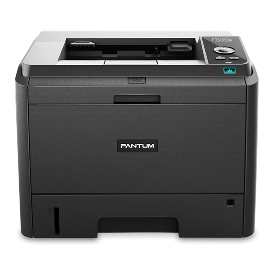
1.2. Product view Front view Paper output slot Store paper printed Control panel Indicate printer status and set the printing Paper output tray Prevent paper printed from dropping Front cover Open front cover and take out laser cartridge Multifunctional input Open multifunctional input tray and put into printing medium tray Paper deflector of... -
Page 12: Control Panel
About 10,000 sheets (the data above is obtained according to the cartridge standard ISO/IEC 19752) Note: Note: Except for Pantum genuine one, you are not suggested to use other consumables. Warranty does not cover damage resulted from your using non-Pantum consumables. 1.3. Control panel Layout and function of control panel... - Page 13 Name Function LCD display screen Provide product information concerned and set product setting. “Page up” key Press this key to roll and scan diverse menus and their options; For menu item required for input, circulate and increase a numerical value. “Menu”...
-
Page 14: Installation Of Printer
Status indicator lamp Bicolor LED lamp can give off red, orange and green light and the specific functions are as follows: Red light: Serious errors, such as failure of laser cartridge installation, mismatching of laser cartridge, carton paper out, etc.; red light constant For error details, please see Chapter 10 Troubleshooting. - Page 15 b) Open front door and take toner cartridge out. c) Hold handle of toner cartridge and (horizontally) shake it for five or six times to make toner in cartridge dispersed evenly. d) Remove black cartridge protection paper.
- Page 16 e) Pull strip seal out. Install cartridge along with guide rail and press it along with direction of arrow; installation will be finished if there is clicking sound. g) Close front cover. h) Power on.
- Page 17 Finish connection.
-
Page 18: Printing Of Product Report
1.5. Printing of product report Print the product report through operating control panel and the product report can help you understand product information and diagnose and settle product failure. a) Press “Menu” key to enter menu setting interface. b) Press direction key “▲” or “▼” and choose the option “6. Print information report”. 菜单设置... - Page 19 size B5, IS0 B5, B6, Letter, Legal, Executive, Folio, Oficio, Statement, 16K, Big 16K, 32K and Big 32K. Medium 60 - 105 g/m² weight Max. capacity of 250 sheets P3500 series Medium Common paper, thick paper, thin paper, transparent cover type paper, card paper, label paper and envelope paper Automatic*, A4, A5 (short edge), A5 (long edge), A6, JIS...
- Page 20 The reason for that may be incorrect operating, unsuited temperature and humidity or other factors that Pantum fails to control. Prior to your purchasing lots of printing medium, please make sure that all the printing medium conform to the specifications designated in the Manual.
-
Page 21: Paper Feed
applicable to laser printer and specification of the product, except for the approved conforming to weight specification one applicable to the product. of the product. 2.2. Paper feed 2.2.1. Paper feed for Standard paper feed box Draw standard paper feed box out of the printer completely. Slide paper length and width deflectors of the paper feed box to paper size stuck slot required and match length and width of paper. -
Page 22: Paper Feed Of Multifunctional Input Tray
dial setting, there will be the error report “Paper size mismatching” on printer LCD display screen; at this moment, you need set the dial again for troubleshooting. • Where there is no required paper matrix displayed on dial, you can set paper size through the way of “menu key of control panel –... - Page 23 Slide paper deflector of multifunctional input tray to match two sides of paper. Any overexertion is not allowed; otherwise, there will be paper jam or skew. Use your hands to put envelop, transparent film or other printing medium into multifunctional input tray and make front end of the medium reach guide roll.
-
Page 24: Paper Feed Of Matching Paper Box
2.2.3. Paper feed of matching paper box The printer can be attached with matching paper feed box and each box can contain 550 sheets of 80 g/㎡ paper at most. If it is required to purchase this kind of box, please contact the local dealer from who you purchase the printer. -
Page 25: Non-Printing Area
dial setting, there will be the error report “Matching paper feed box - paper size mismatching” on printer LCD display screen; at this moment, you need set the dial again for troubleshooting. •Where there is no required paper matrix displayed on dial, you can set paper size through the way of “menu key of control panel –... -
Page 26: Installation And Unloading Of Drive Software
• Before program operates, user’s identity will be judged; where it is administrator identity, the interface will be displayed; where not, the prompt “Insufficient privileges, please install Pantum xxxx series printer with the rights of administrator”. - Page 27 After Autorun operation finishes, it will enter the installation interface below: Note: Display on interface may be different due to difference of type. Option instructions: • “Installation language”: The default is the corresponding language of system; users can choose different languages as required.
- Page 28 Click “Return” and you will return to the original interface. Installation procedure interface Choose “Install” and you will enter drive installation procedure interface. Where there pops up the prompt that Windows fails to verify the publisher of this drive program software and you are asked about whether going to continue the installation, you need click “Continue”...
- Page 29 Installation completion System will enter the interface below after completing the drive installation. System will quit it in 3 s automatically and set the printer as default. Network type installation (wired and wireless) 3.1.2.2. Interface operation Insert the CD and main interface will pop up and program will operate automatically. Installation configuration...
- Page 30 Enter installation configuration interface after interface operation finishes. You can choose the model of printer that you need to install and the corresponding series; choose the language and installation way. Installation way installations: “USB printer”: Applicable to local installation of all types. “Printer connected onto network”: Applicable to network installation of Net type or to the second installation of Wi-Fi type connected onto network.
- Page 31 You can choose the corresponding wired type through “Choose printer” and choose the corresponding installation mode through “installation way”. Printer search interface When system enter printer search interface, program will search the printer and check whether computer has been connected with appropriate printing equipment. Selection of printer list System will enter “Choose printer”...
- Page 32 Note: • You can choose the corresponding printer name form “Searched printers”; • Where there is no printer name displayed in “Searched printers”, please click “Refresh” to search printer connected onto the network; • If knowing the IP address of the printer to be connected, you can choose “Install by designating IP address” and input IP address of the printer for installation.
- Page 33 You can choose the corresponding Wi-Fi type through “Choose printer” and choose the corresponding installation mode through installation way. If it is the first time of installation, you s should choose the third installation way. Wi-Fi configuration interface...
-
Page 34: Drive Program Unloading
3.1.3. Drive program unloading Selection of unloading way Click “Start”-“All programs” to find “Pantum” folder; then click the name of product to be unloaded to enter unloading interface; Or click “Start”-“Control panel”, click “Unload program” to enter the interface and... - Page 35 Click “OK” button in information prompt dialog box and the dialog will disappear. If there is the task in printing list, there will pop up warning prompt: “Pantum P3500 Series laser printer is operating; please unload the drive after printing completion”. The prompt is shown as below:...
-
Page 36: Mac System-Based Drive Software Installation
Completion interface After progress bar advances at the end, system will enter completion interface. Click “Finish” button and there will pop up prompt window of computer reboot. Click “OK” to quit unloading program and reboot the computer; Click “Cancel” to quit unloading program. 3.2. - Page 37 b) Permission Click “Continue” in the picture above to display the permission protocol; the interface is shown below: c) Click “Continue” and the dialog box “If continuing software installation, you must agree the terms in software permission protocol.” will pop up.
- Page 38 You cannot continue the installation until you click “Agree” button and accept the permission protocol. d) Installation type Display installation information concerned. The typical drawing is shown below. Click “Install” and the prompt dialog box below will pop up; you will continue the installation after login with identify of administrator.
- Page 39 e) Installation Typical drawing of installation progress is shown as below: f) Summary Typical completion of installation progress is shown as below:...
-
Page 41: Network Configuration (Applicable To The Type Supporting Wired/Wireless Network Function)
4. Network configuration (applicable to the type supporting wired/wireless network function) 4.1. Wired network configuration (applicable to the type supporting wired network function) a) Printer supporting wired network printing can be connected to LAN and thus printing can be implemented after connecting printer through wired network. b) In this configuration, the product can be connected to network directly and network sharing printing can be implemented through the setting of “allow all computers connected to network finish printing by the product”. -
Page 42: One-Click Wireless Configuration
Wi-Fi configuration tool is the computer-end configuration software that facilitates users to set the network name, encryption mode and password of printer. Please use USB cable to connect printer and computer and then use Pantum wireless network configuration tool to configure the wireless network of printer in computer. - Page 43 Note: This interface is entered after configuration tool is started. Information, such as wireless network names, searched is shown on network list and is ranked by “network name”. Users can select an item in the list and double click or click “Next” to enter information input interface. “Manually enter the network name”: click it to switch to the manually input network name interface, i.e.
- Page 44 Input the network name to be connected by printer in “Network name” field. Click “Print wireless network information page” to print wireless network list searched by the printer. Note: If there is job to be completed by the currently configuring printer, the following error prompt window will pop up.
- Page 45 Note: • Safety mode is currently divided into: None, WEP and WPA/WPA2. When the mode is “None”, the password input field is hidden, which means password is not required for connection of SSID filled. The input range of WEP is 1-26 characters. The input range of WPA/WPA2 is 8-64 characters. •...
- Page 46 If the printer is not connected to computer, the information below will pop up: “please use the USB cable provided to connect printer with computer”. Click “Next”, the program will search the printer device that is currently connected to PC automatically. If no printer model that is supported by this tool can be searched, the system will stay in this interface.
- Page 47 “Trying to set up wireless connection with printer”. If the printer fails to configure with the wireless network provided, the following information will pop Printer fails to connect to wireless network with the wireless voucher provided. To input it again, please click “Back”.
- Page 48 If the printer can use the wireless network provided to configure, but the PC does not support wireless network, the following information will pop up: “The printer can use the wireless voucher provided to connect to wireless network. However, this PC computer cannot communicate with printer”.
- Page 49 Note: This interface is entered after configuration tool is started. Information, such as wireless network names, searched is shown on network list and is ranked by “network name”. Users can select an item in the list and double click or click “Next” to enter information input interface. “Manually enter the network name”: click it to switch to the manually input network name interface, i.e.
- Page 50 Click “manually enter the network name” to switch to the manually input network name interface. “Network name”: Input the network name to be connected by printer, the largest length is 32 characters. “Print wireless network information page”: The wireless network list searched by the printer can be printed. “Next”: Enter information input interface.
- Page 51 Note: • Safety mode is currently divided into: None, WEP and WPA/WPA2. When the mode is “None”, the password input field is hidden, which means password is not required for connection of SSID filled. The input range of WEP is 1-26 characters. The input range of WPA/WPA2 is 8-64 characters. •...
- Page 52 If the printer is not connected to computer, the information below will pop up: “please use the USB cable provided to connect printer with computer”.
- Page 53 Click “Next”, the program will search the printer device that is currently connected to PC automatically. If no printer model that is supported by this tool can be searched, the system will stay in this interface. If there is printer model that is supported by this tool searched, the following information will pop up: “Trying to set up wireless connection with printer”.
- Page 54 If the printer can use the wireless network provided to configure, but the PC does not support wireless network, the following information will pop up: “The printer can use the wireless voucher provided to connect to wireless network. However, this PC computer cannot communicate with printer”.
-
Page 55: Configure Via Web Server
If the printer can use the wireless network provided to configure, and the PC supports wireless network, the following information will pop up: “The printer can use the wireless voucher provided to connect to wireless network”. 4.2.3. Configure via Web server You can use the Web server built in printer for wireless connection. -
Page 56: Turn On/Off Wireless Device
Click “wireless network” to enter wireless network configuration interface. 4.2.4. Turn on/off wireless device To disconnect the product and wireless network, users can turn off the wireless device of product through the menu button on control panel. a) Press “menu” button to enter menu setting interface. -
Page 57: Set Network Printer
b) Press direction key “▲” or “▼” to select “4. Network settings” and then press “OK” button. c) Press direction key “▲” or “▼” to select “2. Wireless network settings” and then press “OK” button. d) Select “1. Wireless network” and press “OK” button; select “1. Off” and then click “OK” to turn off wireless network. - Page 58 Note: This printer supports HTTP application protocol; therefore, users can have secure encrypted access to the https://xxxx…they input in Web browser. b) Network settings and machine settings can either be realized in “Settings”. Moreover, network protocol, wireless network and wireless hotspot settings can be finished via network settings; relevant configuration information setting such as printing preference, e-mail, can be finished via machine settings.
- Page 59 Set or change Web page login password 4.3.1.2. Printer control can be realized through user management settings. Method: a) Open the built-in Web server and log in. The login page is as shown below: Note: The default user name of product is “admin”, and the initial password is “000000”. b) Click "User Management"...
- Page 60 d) Single click “modify’ button at the bottom of the window to save the setting. IP address 4.3.1.3. The IP address of product can be set up via DHCP function automatically or manually. | Auto setup DHC auto setup function of the product is defaulted activated. Connect the product to network via network cable and complete startup preparation.
-
Page 61: Control Panel Settings
Note: • The built-in Web server can be used to change the allocation mode of IP address to “Auto” or “Manual”. • To reset all parameter settings of the product, users can restore factory settings. Refer to Chapter 6 for details. - Page 62 Network information 4.3.2.2. Users can check network status through network information. Press “Menu” button to enter menu settings interface. Press direction key “▲” or “▼” to select “5. Network information” and then press “OK” button. Press direction key “▲” or “▼” to select “1. Wired network information”, “2. Wireless network information”...
- Page 63 Select “3. Wi-Fi direct information” and then press “OK” button; press direction key “▲” or “▼” to select “1. Status”, “2. Device name”, “3. IP address”, “4. Password”, “5. Channel” and “6. Number of devices connected”.
-
Page 64: General Structure Diagram
5. General Structure Diagram 5.1. General structure 图文字 译文 RMA 模块 RMA module 接口模块 USB Interface module USB 外接设备 External equipment 低压电源供给模块 Low-voltage power supply module 数据控制模块 Data control module 操作模块(控制面板) Operation module (control panel) 引擎控制模块 Engine contorl module 高压电源供给模块 High-voltage power supply module 激光单元... -
Page 65: Mechanical Structure Diagram
粉盒单元 Powder compact unit 转印模块 Transfer module 充电模块 Charging moudle 曝光硒鼓 Exposure toner cartridge 清洁模块 Cleaning module 显影模块 Developing module 纸盒 Paper tray 定影单元 Fuser unit 出纸模块 Paper-out module 进纸系统 Paper feed sytem 成像系统 Image system 5.2. Mechanical Structure diagram... - Page 66 Rear cover Paper-out roller component 1 Heating roller Feed-out sensor Impression roller Transfer roller Apex sensor Calibration sensor Paper-out roller 2 Clamp Laser Feed-out tray Charge roller Developer roller Powder supply roller Calibration shaft Calibration roller Bypass tray Conveying roller Paper end sensor Paper sensor Pickup roller...
-
Page 67: Paper Feed Path
5.3. Paper feed path 双面打印进纸路径 Paper feeding path for two-sided printing 手送进纸路径 Manual paper feeding path 纸盒进纸路径 Paper tray feeding path... -
Page 68: Hardware Disassembly
6. Hardware disassembly 6.1. Explosion diagram - printer... -
Page 69: Explosion Diagram - Optional Paper Tray
6.2. Explosion diagram – optional paper tray 二层纸盒左盖 Left cover of two-layer paper tray 二层纸盒右盖 Right cover of two-layer paper tray 框体部分 Frame part 基板 Base plate 马达 Motor 给纸组件 Paper feeding component 末端感应臂 End sensory arm 纸有无感应臂 Paper sensory arm 纸盒组件... -
Page 70: Disassembly Steps - Printer
6.3. Disassembly steps – printer 图文字 译文 前盖板 Front cover plate 左侧盖板 Left cover plate 右盖板 Right cover plate 右侧盖板 Right cover plate 上盖板 Upper cover plate 控制面板 Contorl panel 纸满传感器 Paper full sensor USB 接口 USB interface 电磁铁 Electromagent 齿轮组... -
Page 71: Disassembly Steps - Optional Paper Tray
分离齿轮组件 Separating gear component 转印辊 Transfer roller 多功能纸盒分离片 Multi-function paper tray separator 多功能纸盒齿轮组 Multi-function paper tray gear set 多功能纸盒搓纸轮 Multi-function paper tray pickup roller 多功能纸盒纸张传感器 Multi-function paper sensor 6.4. Disassembly steps – optional paper tray 纸型选择 离合器组 左侧盖板 右侧盖板 控制基板 马达... -
Page 72: Disassembly Diagram - Printer
6.5. Disassembly diagram - printer 6.5.1. Preparation before disassembly Turn printer power off. b) Open the front cover and take the toner cartridge running out along the guides. Protect toner cartridge to prevent image quality from being affected by exposure. d) Take paper tray out. - Page 73 Take duplex unit out. 6.5.2. Front cover plate 注意传感器连线 Pay attention to sensor wiring 拆除前盖板时,先拆除左边 When dismantling front cover plate, dismantle the left one first 6.5.3. Left cover plate Remove the 2 rear screws.
- Page 74 b) Pry to remove the left cover plate in accordance with the giving directions.
- Page 75 6.5.4. Rear cover plate 6.5.5. Right cover plate Pay attention to paper size sensor while removing the right cover plate. 6.5.6. Upper cover plate Cut off the 3 connecting wires shown in the photo.
- Page 76 Remove the screws, 2 in the rear, 1 in the left and 2 in the right, shown in the positions below. Kick out the left and right bayonets as shown in the photo and lift up the upper cover plate.
- Page 77 6.5.7. Control panel Keypad (it is connecting to the display screen by flat cables, pay attention to the flat cables while disassembling!) Display screen...
- Page 78 6.5.8. Paper full sensor 6.5.9. USB interface It is the port reads data devices other than the interface connecting to computer.
- Page 79 6.5.10. Engine base board Note: After taking the engine base board down, users can see 4 conductive poles. Please take care of them and do not make them lost. Please pay attention and install the conductive poles in right places. One conductive pole is different from the other 3 and as it is an OPC conductive pole.
- Page 80 6.5.11. Data base board Remove data base board connectors and wireless antennas. b) Remove screws and take data base board down.
- Page 81 6.5.12. Power base board 6.5.13. Fan Please disconnect fan wires and then remove the fan.
- Page 82 6.5.14. Paper size selector assembly 6.5.15. Optional paper tray interface 6.5.16. Gear set Remove the 5 fixing screws down and take the drive system down.
- Page 83 6.5.17. Electromagnet Paper feeding electromagnet Unplug electromagnet connecting wire, remove the fixing screws and then take the electromagnet down. b) Two-sided electromagnet Pull out electromagnet connecting wire, remove the fixing screw and take the electromagnet down.
- Page 84 6.5.18. Feed-out component Remove fixing screws and take feed-out component down. 6.5.19. Fuser Component Pull out the cable of fuser component.
- Page 85 Take fixing screws (1 in the left, 1 in the right and 4 in the rear, 6 in total) down and then take the fuser component down. 6.5.20. Laser Unplug laser connecting wire, remove the fixing screw and take the laser down.
- Page 86 6.5.21. Motor Prop up the fixing jack catches of motor protection cover and then take the motor protection cover down. Remove fixing screws through the motor and then take the motor down.
- Page 87 6.5.22. Pickup roller Take the locating pin of pickup roller down and then take the pickup roller down. 6.5.23. Bottom cover and conveying sensor Remove the fixing screws of bottom cover and then take the bottom cover down.
- Page 88 Unplug the connecting wire of inductive base board. 6.5.24. Separating gear component Remove the plastic cover plate of clutch gear.
- Page 89 Remove the spring and then take the locating pin down. Take the clutch gear sleeve and spring down.
- Page 90 Move the clutch shaft for paper feeding and take the clutch gear down. 6.5.25. Transfer roller Loosen the claw chuck of the bearings at both sides of transfer roller and take then transfer roller down.
- Page 91 6.5.26. Multi-function paper tray separator 6.5.27. Multi-function paper tray separating gear component...
- Page 92 6.5.28. Multi-function paper tray pickup roller Prop up the sleeve at the left side of pickup roller. Prop up the sleeve at the right side of pickup roller. Separate the connecting rod of pickup roller. Take the pickup roller component down and pay attention to spring position.
- Page 93 6.5.29. Paper sensor of multi-function paper tray Prop up the cover plate of paper sensor according to the diagram Disconnect the connecting wire and take the paper sensor down.
-
Page 94: Disassembly Diagram - Optional Paper Tray
6.6. Disassembly diagram – optional paper tray 6.6.1. Preparation before disassembly Turn printer power off, disconnect the power line and separate the printer and optional paper tray. Take the paper tray down. - Page 95 6.6.2. Left cover plate of optional paper tray 6.6.3. Right cover plate of optional paper tray The disassembly method is the same as the disassembly method for left cover plate. Special attention should be paid to the position of paper selector.
- Page 96 6.6.4. Control base board of optional paper tray 6.6.5. Motor of optional paper tray 6.6.6. Gear set of optional paper tray...
- Page 97 6.6.7. Paper size selector of optional paper tray 6.6.8. Clutch component of optional paper tray Remove gear limit bayonet.
- Page 98 Rotate gear locator clamp to this position with straight screwdriver according to the direction shown in the diagram. 6.6.9. Female interface of optional paper tray Disconnect the connecting wire. Prop up the bayonet according to the diagram.
- Page 99 6.6.10. Male interface for optional paper tray 6.6.11. Pickup roller for optional paper tray...
- Page 100 6.6.12. Sensor connecting rod of optional paper tray Press the bayonet of fixing connecting rod down, and then make the connecting rod come off in the left side. Prop up the steel shaft limit clamp, pull out the steel shaft in the right side and separate the connecting rod at last.
- Page 101 6.6.13. Paper sensor of optional paper tray 6.6.14. Conveying sensor of optional paper tray 6.6.15. Separator of optional paper tray Break off according to the direction shown in the diagram. Break open with straight screwdriver at one side.
-
Page 102: System Settings
Break open according to the direction shown in the diagram and then take the separator down. 7. System Settings 7.1. Language Setting "Language Setting" is used to select the language to be displayed on the control panel. Default language is “Chinese”. -
Page 103: Sleep Time Setting
7.2. Sleep Time Setting Set the Sleep Mode to lower the power consumption. “Sleep Time Setting” allows you to select the idle time before the device enter into Sleep Mode. Press "Menu" button to enter the menu interface. Press "OK" key to select "1. System Settings". Press direction key "▲"... - Page 104 4) Press direction key "▲" or "▼" to select "1. Close" and press "OK" button. When symbol "*" appears after "1. Close", it indicates that the toner save setting is off; or press direction pad "▲" or "▼" to select "2. Open" and press "OK" button. When symbol "*" appears after "2. Open", it indicates that the toner save setting is on.
-
Page 105: Restore Factory Settings
7.4. Restore factory settings “Restore factory settings” is used to restore to printer default settings. 1) Press “Menu” key to enter menu setting interface. 2) Press "OK" key to select "1. System Settings". 3) Press direction key “▲” or “▼”, select “4. Restore factory settings” and press “OK”. -
Page 106: Print
8. Print 8.1. Printing function You can select various property settings from Printing Preference to realize the following printing functions. Functions Diagram Auto Duplex Print Collate Print Reverse Print N-in-1 Poster Print (for Windows System only) -
Page 107: Paper Tray Settings
Zoom Print Custom Size Note: • You can select the 2 x 2 Poster printing from N-in-1 option to use the poster printing function. • You can open the Printing Preferences and click Help button to check the specific function explanation. For information about how to open the help document, see Chapter 7. -
Page 108: Paper Tray Setting On Control Panel
Note: • when a paper size to be set cannot be found on the dial, the user can set it on the control panel of printer. Please refer to Chapter 7. 8.2.2. Paper tray setting on control panel Note: The paper size settings of standard tray, multi-function tray, and optional tray can be done on control panel. -
Page 109: Open The Help Document
Press the direction key “▲” or “▼” to select “2. Paper sheet size” option. Start setting. 8.3. Open the help document You can open the “printing preference” and click “help” button (for windows system only). The help document relates to the user guide of printer, providing you with the printer related setting information. -
Page 110: Printing Method
8.4. Printing method This printer is capable of standard input tray printing, multifunctional input tray printing, and optional tray printing. If the multifunctional input tray contains a printer medium, this medium printing has the priority. Precedence for this printer: multifunctional input tray > standard input tray > optional tray. 8.4.1. -
Page 111: Printing With Multifunctional Input Tray
Note: • For paper feeding related precautions, please refer to Chapter 2. • For the medium type related to printing of standard input tray, please refer to Chapter 2. • If the multifunctional input tray holds medium, please select “standard input tray” as the paper source through the menu key “2. - Page 112 Insert the power line into the printer, and turn on the power. Note: • Before installation or moving of the optional tray, please cut off the power supply to the printer. • After installation of optional tray, do not raise the printer during printing. Otherwise, the optional tray communication fails.
- Page 113 When the multifunctional input tray and standard tray hold no paper, or when the user set “optional tray I/II” as the paper source, the printer will finish printing task with paper fed from optional tray. Note: • The optional tray can hold 550 pages of 80 g/m common paper, as a maximum.
-
Page 114: Automatic Duplex Printing
Note: • Before disassembly of optional tray, please make sure the printer power is off. 8.5. Automatic duplex printing The driver software of this printer supports automatic duplex printing of common paper. Paper sizes supported by automatic duplex printing include: A4/LETTER, LEGAL, OFICIO, and FOLIO. Note: •... - Page 115 When you put paper into the multifunctional input tray, this printer will select the printing paper inside multifunctional input tray in priority. Note: • The multifunctional input tray can realize automatic duplex printing, but it can hold 60 pages of paper at most.
- Page 116 c) Select the printer according to the corresponding model shown in the figure. d) Click the “preference option” or “attribute” button, for printing configuration. e) Select the “duplex printing” area under “basic” tab, with “long side” or “short side” binding style optional.
- Page 117 f) Click “OK” to complete printing settings, and then automatic duplex printing is realized.
-
Page 118: Routine Maintenance
Note: • It is recommended to raise paper supporting board, preventing the printed paper from slipping from the paper tray. If you select not to raise the paper supporting board of output tray, we recommend you take away the printed paper immediately after it is output. •... -
Page 119: Maintenance Of Laser Carbon Powder Box
9.2.1. About laser carbon powder box Use and maintenance of laser carbon powder box In order to achieve higher printing quality, please use the original PANTUM laser carbon powder box. Matters needing attention during use of the laser carbon powder box: ... -
Page 120: Replacement Of Laser Carbon Powder Box
9.2.2. Replacement of laser carbon powder box Note: Please read following matters needing attention before you replace a laser carbon powder box: • Take the laser carbon powder box out with care to avoid the possible powder on the surface of laser carbon powder box from scattering. -
Page 121: Troubleshooting
Please read this chapter carefully, because it can help you in solving frequently-seen troubles during printing. If you still cannot solve the present problem, please contact the after-sales service center of PANTUM. Before you handle the frequently-seen troubles, please check the following conditions: •... -
Page 122: Clearing Paper Jam
• If you cannot take out the stuck paper by yourself, please contact the local authorized maintenance center of PANTUM, or send the printer to the nearest authorized maintenance center of PANTUM. 10.1.1. Paper jam inside tray Open the paper tray Draw the stuck paper gently out. -
Page 123: Hand-Operated Paper Jam Inside Tray
10.1.2. Hand-operated paper jam inside tray Draw the stuck paper out gently and straightly. Put the jammed paper again into the tray after removing, and the printer will automatically recover printing. 10.1.3. Paper jam inside optional tray If paper jam occurs inside optional tray, please operate as indicated on the LCD display screen of control panel, to remove the stuck paper. - Page 124 Please put the paper tray again into the printer after taking out the jammed paper, and then the printer will automatically recover printing. If you cannot see any paper in this area, please stop and skip to the next step: Open the standard input tray.
-
Page 125: Paper Jam In The Middle Part
Put the paper tray again into the printer after taking out the jammed paper. 10.1.4. Paper jam in the middle part Note: • If you are taking out the paper stuck in the middle part or in the fixation unit, please take care not to touch the following dash area, to avoid burn. -
Page 126: Paper Jam Inside Fixation Unit
d) Put the tray again into the laser carbon powder box after taking out the jammed paper, and close the front cover. The printer will automatically recover printing. 10.1.5. Paper jam inside fixation unit Open the rear cover. Open the fixation decompression unit through the handles at both sides of printer. Draw the stuck paper out gently. -
Page 127: Paper Jam Inside Duplex Unit
Then, the printer will automatically recover printing. 10.2. Software disaster Trouble Solution Pantum 3500 Series printer driver software Re-install the printer driver software. cannot be found in the printer or facsimile Please make sure the USB connecting line and power line folder. -
Page 128: Troubleshooting
The printing medium is affected with damp or Recommend to use the recommended bonded together. medium. Internal parts are out of order. Please separate the printing media again or dry them better. Note: If the problem remains unimproved, please contact the customer service of PANTUM. -
Page 129: Serious Troubles
No display on the display The display screen or Replace the base plate of control panel screen control panel is damaged. (including display screen). “Pantum” displayed after Self inspection is the boot unfinished, and the data Replace the data base plate. Reheating displayed after base plate damaged. -
Page 130: Image Defects
Printer internal trouble 10 Please contact the customer Not reach the paper pickup temperature services 1, Replace the engine base Printer internal trouble 11 Engine system failures (engine plate; Please contact the customer communication failure; engine in boot 2, Replace the power base services stage;... - Page 131 transfer printing or damaged transfer roller. Vertical black Cleaning doctor is chipped or deformed. lines/bars OPC is damaged. Replace the toner cartridge. There are foreign matters between developer roller and doctor blade. Laser window glass is contaminated. Vertical white Clean the laser window glass. There are foreign matters or carbon powder particles between developer Replace the printing toner cartridge.
-
Page 132: Appendix 1 Perimeters Of Various Rollers
Laser is damaged. Replace the laser. Note: The above troubles may be improved by cleaning, replacing the laser carbon powder box, and other methods. If problems remain unimproved, please contact the customer service of PANTUM. Appendix 1 Perimeters of Various Rollers... - Page 133 Transfer roller 43.99 Heating roller 77.60 Impression roller 78.54 75.27 Developer roller 35.13 Powder feeding roller 46.64 Power charging roller 38.01 If any related periodic image abnormality is found, its cause may be judged according to the perimeters listed above.
-
Page 134: Appendix 2 Line Chart
Appendix 2 Line Chart... -
Page 135: Appendix 3 Serial Number (Sn) Descriptions
Appendix 3 Serial Number (SN) Descriptions Each set of machine has its own product serial number tab pasted up. Below are the meanings of serial number code and positions where they are pasted up. Code meaning: Production date Product serial number BA2 A 000001 7DC 01 Serial number (6 digits) -
Page 136: Appendix 4 Terminology Explanation
Appendix 4 Terminology Explanation All special terms involved in this manual are explained as below: Term Explanation A kind of safety standard for laser products Scanner Number of dots per inch Number of pages printed per minute Weight of paper sheet in a m unit auto run Automatic running... - Page 137 Zhuhai Seine Technology Co., Ltd. Add.: Middle Zone A, 3/F, Building 01, No. 3883, Zhuhai Avenue, 519060, Zhuhai City Website: www.pantum.com Tel.: 400-060-1888...
Need help?
Do you have a question about the P3500 Series and is the answer not in the manual?
Questions and answers