Table of Contents
Advertisement
Quick Links
Advertisement
Table of Contents
Troubleshooting

Related Manuals for Pantum P3000 Series


Summary of Contents for Pantum P3000 Series
-
Page 2: Legal Notices
Legal notices Trademark Pantum and Pantum logo are registered trademarks of Zhuhai Seine Technology Co., Ltd. Microsoft, Windows, Windows server and Windows Vista are either registered trademarks of Microsoft Corporation in the United States and other countries. The ownerships of software names related to this Maintenance Manual in accordance with corresponding license agreement belong to their respective owned companies. -
Page 3: Safety Information
To avoid the possible risk of damage to the product, it is strongly recommended that maintenance be carried out by trained technicians from Pantum, rather than untrained personnel. User will bear the responsibility for any personal injury or product damage occurring during maintenance of this product and the components specified in this manual. - Page 4 Installation The printer should be placed on a flat and stable surface, such as a desktop, away from people and from sources of vibration, and close to a regular, grounded power supply outlet. The ambient temperature of the installation site should be between 10° C and 32.5° C, with humidity between 20% and 80%.
- Page 5 Laser Safety Laser radiation is harmful to the human body. Since laser components are completely sealed within the printer, there should be no radiation leaks. To prevent laser radiation leaks. DO NOT RANDOMLY DISASSEMBLE THE PRINTER. The printer follows the provisions of Class 1 laser products under the CFR standard. The printer has a Class ⅢB laser diode, which does not have laser components containing radiation.
-
Page 6: Table Of Contents
Index 1 AN INTRODUCTION TO THE PRODUCT ......................1 OVERVIEW ................................1 1.1.1 FRONT VIEW ................................ 1 1.1.2 REAR VIEW ................................2 PRODUCT SPECIFICATIONS ............................3 1.2.1 GENERAL SPECIFICATIONS ........................... 3 1.2.2 PRINTING SPECIFICATIONS ..........................4 1.2.3 CONSUMABLES SPECIFICATIONS ......................... 5 INSTALLATION AND BASIC INSTRUCTIONS .................... - Page 7 3.4.4 TRANSFER ................................5 3.4.5 SEPARATION ................................ 5 3.4.6 FIXING .................................. 6 3.4.7 CLEANING ................................6 DUPLEX PRINCIPLE ..............................6 SENSOR ..................................7 DISASSEMBLY AND INSTALLATION ....................... 1 DISASSEMBLY DIAGRAM ............................1 STEP-BY-STEP DISASSEMBLY DIAGRAM ........................2 DISASSEMBLY STEPS ..............................3 4.3.1 PREPARATION FOR DISASSEMBLY ........................
- Page 8 PRE-MAINTENANCE CHECK............................7 INDICATORS ................................8 6.2.1 LED INDICATOR INSTRUCTIONS ........................... 8 6.2.2 LED STATUS INSTRUCTIONS ..........................8 6.2.3 BUTTON INSTRUCTIONS ............................ 10 ERROR INFORMATION ............................11 ERROR CODE ................................12 CLEARING JAMMED PAPER ............................ 13 6.5.1 PAPER JAM IN THE TRAY ............................ 13 6.5.2 PAPER JAM IN THE MANUAL FEEDER TRAY .......................
-
Page 9: An Introduction To The Product
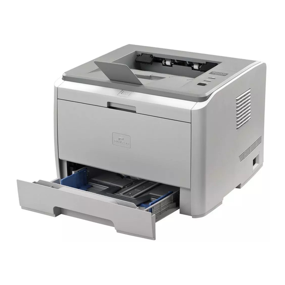
1 An Introduction to the Product 1.1 Overview 1.1.1 Front View Output Bin: Used to store printed paper Display Panel: Indicates the print status Output Tray: Prevents printed paper from falling out Front Cover: The laser toner cartridge can be removed by opening the front cover Manual Feeder Tray: Print media can be manually inserted by opening the front cover of the manual feeder tray Manual Feeder Tray Guide: Adjusts the paper width... -
Page 10: Rear View
1.1.2 Rear View USB Interface: Directly connects to the computer Network Interface: Connects the printer to the network Power Interface: Connects the power cord Rear Cover: For dealing with paper jams Duplex Unit: For duplex printing... -
Page 11: Product Specifications
1.2 Product Specifications 1.2.1 General Specifications Standard 64MB Memory Extensibility None Interface Type USB2.0, 10BASE-T/100BASE-TX Ethernet Microsoft Windows Server2003/Server2008/Server2012/XP/Vista/7/Win8 (32bit Operating System & 64bit) Mac OS X 10.4/10.5/10.6/10.7/10.8 Power AC 220V~240V 50/60Hz Maximum Power Under 780W Consumption 495W Print Stand-by Average Power Sleep mode... -
Page 12: Printing Specifications
1.2.2 Printing Specifications Printing Mode Laser Print Speed (PPM) 30 or 33 depending on model (standard A4) 1200*600 Resolution (dpi) Legal (216mm x 355.6mm) Maximum Print Size Automatic Duplex Built-in Network Print Function On Network models (wired network print) Multipurpose 1 page Tray Input... -
Page 13: Consumables Specifications
•Actual reference may vary depending on country. •Model specifications are subject to change without notice. •Consumables capacity may vary depending on different varieties used. Note: For optimal print quality, please use only original Pantum products. The warranty excludes damage caused by using non-Pantum original consumables. -
Page 14: Installation And Basic Instructions
2 Installation and Basic Instructions 2.1 Unpacking the Product When you open the package, make sure that the following parts are included in the box: Parts Name Quantity Printer Toner Cartridge USB interface cable Power cord CD-ROM Quick Setup Guide Pantum Warranty... -
Page 15: Installing The Printer
2.2 Installing the Printer 2.2.1 Removing the packaging materials After unpacking the printer, dismantle the adhesive tape and the protective cover. 2.2.2 Installing Consumables 1. Press down the front cover button. 2. Open the front cover and remove the toner cartridge. - Page 16 3. Hold the handle of the toner cartridge and shake gently (horizontally) 5-6 times, so as to evenly distribute the toner inside the cartridge. 4. Remove the black paper protecting the toner cartridge. 5. Pull out the sealing tape.
- Page 17 6. Load the toner cartridge along the guides, and press along the direction of the arrow until you hear a click, indicating that the installation is complete. 7. Close the front cover.
-
Page 18: Installing And Uninstalling Driver Software
The user’s identity will be verifed before the program starts running. If the user is an administrator, this interface will display. If the user is a not an administrator, the “Insufficient privileges. Please install Pantum P3000 Series Printer with administrator privileges.” prompt will pop up. - Page 19 2) Installation Language Once the program has started running, you will be taken to the next dialog where you can change the default installation language. 3) License Agreement Click the Next button to enter the License Agreement interface. Please read the end user license agreement carefully and agree by selecting the “I Agree”...
- Page 20 Pantum P3000 Series printers. Users can click on User Guide on the interface to read the corresponding documents. 4) Search for Printers After selecting “I Agree” and clicking Next, you will be taken to the Search for Printers interface and the program will automatically search for the appropriate printer device connected to the computer or to the network.
- Page 21 Note: • Detected Printer and Specify an IP Address for Installation cannot both be selected. If the appropriate printer device is not detected, click “Next”, the dialog box “No printer has been detected. Do you still want to proceed with the installation?” will pop up. If you select “Yes”, the program will proceed with the installation and take you to the Copy interface.
- Page 22 7) Driver Installation If Windows cannot verify the publisher of this driver software during the driver installation process, you will be asked if you still wish to proceed with the installation. You need to click “Continue Anyway” or “Always Install this Driver Software”, otherwise the installation will be unsuccessful (the warning pop-ups may differ slightly depending on the operating systems).
- Page 23 8) Completing Installation After the driver installation progress bar shows that the installation is complete, you will be taken to the Installation Complete interface. Click the Done button to complete the installation of the printer driver, carry out online product registration which can provide online services and other information, and set this printer as the default printer.
-
Page 24: Driver Uninstall
2.3.1.2 Driver Uninstall 1) Selecting the Uninstall Mode In the Start menu, select the Pantum Uninstall entry to launch the Uninstall wizard, or find the Add/Remove option in the control panel, find the relevant Pantum options, and click Change and Delete, a Welcome interface will pop up. - Page 25 4) Done Interface After the progress bar shows that the process is complete, you will be taken to the Done interface. Click the Done button to complete the uninstall. 2-12...
-
Page 26: Installing The Driver Software On A Mac System
2.3.2 Installing the Driver Software On a Mac System The Mac driver installer operates via the Package Maker software that comes with the Mac OS X system. The installation steps are basically the same as when installing other Mac software and are divided into: introduction, license, destination volume, type of installation, installation, summary. - Page 27 2. License An illustration of the contents of the License Agreement is shown below: Click Continue, the License Agreement Acceptance dialog box will pop up. Click “Agree” to accept the License Agreement and continue the installation. 2-14...
- Page 28 3. Destination Volume Select the installation disk, then the following view will display; Click Continue to display the installation-related information. Note: • In Mac OS X 10.4, you will enter this interface directly, but in Mac OS X 10.5 and later systems, you will enter the Installation Type option interface first.
- Page 29 4. Installation Type An illustration of the installation-related information is shown below: Click Install, the following prompt box will pop up. After logging in as an administrator and getting permission, you can continue with the installation. 2-16...
- Page 30 5. Install An illustration of the installation progress bar is shown below: Click Continue to display the Installation Complete interface. 6. Summary An illustration of the Installation Complete interface is shown below: 2-17...
-
Page 31: Network Settings (For Network Models)
2.4 Network Settings (For Network Models) You may need to set some network parameters for the printer. These parameters can be set from the embedded Web server. 2.4.1 Installing the Printer onto the Network In this configuration, the printer is directly connected to the network and can be set to allow all computers on the network to print directly to the printer. -
Page 32: Setting Network Products
2.4.2 Setting Network Products 2.4.2.1 Viewing or Changing Network Settings You can use the printer embedded Web server to view or change its IP settings. 1. Print DEMO Information Page, for viewing the printer's IP address information. While the printer is in idle state, press the control panel button (as shown below) for 3 seconds to print the DEMO page. -
Page 33: Ip Address
2.4.2.3 IP Address The printer’s IP address can be automatically set through the DHCP function and can also be set manually. | Automatic Setting The DHCP automatic setting function is enabled by default. 1. Connect the printer to the network via a network cable and complete the driver installation; 2. -
Page 34: Test Printing
2.5 Test Printing 2.5.1 Printing the Offline Configuration Page The offline configuration page can be set from the operation panel using the following steps: Power on, making sure the indicator display status reads as Ready. Press down the button on the control panel for 3 seconds to print a test page. 2-21... -
Page 35: Printing The Windows Test
Follow these steps to print using a personal computer: 1) After installing the driver, click on the Start menu on the computer, select All Programs; then, select the P3000 Series Printer Driver and the Printer Status Monitor, as shown below: 2-22... - Page 36 2) The following box will appear with the list of P3000 printers: select the correct printer installed: 3) After double-clicking, the following box will appear: click on the Print Information Page button: 2-23...
- Page 37 4) The Information Page is shown below. 2-24...
-
Page 38: Electric Configuration
3 Electric Configuration 3.1 Whole Configuration... -
Page 39: Mechanical Structural Diagram
3.2 Mechanical Structural Diagram Developing Roller Rear Cover Toner-feed Roller Output Roller Component 1 Correction Axis Heating Roller Correction Roller Delivery Sensor Manual Feeder Tray Pressure Roller Transporter Roller Transfer Roller Paper-end Sensor Paper Feed Sensor Paper Presence Sensor Correction Sensor Pickup Roller Output Roller Component 2 Separator... -
Page 40: Feeder Circuit Diagram
3.3 Feeder Circuit Diagram... -
Page 41: Printing Process
3.4 Printing Process 3.4.1 Charging The steel shaft of the charge roller applies a high-voltage DC bias to the OPC, and evenly charges the surface of the OPC-6 00V with a negative charge. 3.4.2 Exposure When the photoconductor is subjected to irradiation by the laser beam, the charge disappears. Other parts which are not irradiated, still keep their charge to form an electric potential difference image. -
Page 42: Transfer
voltage is higher than the exposed area of the OPC but lower than the unexposed area. When the electrostatic field between the OPC and DR reacts, the toner will adhere to the exposed area of the OPC to form a visible image. 3.4.4 Transfer When the sheet being printed goes through the layer between the transfer roller (TR) and the OPC, high voltage opposite the toner charger is fed to the transfer roller, causing an electric field... -
Page 43: Fixing
3.4.6 Fixing The heat roller should reach the designated temperature necessary to melt the toner when the sheet is in contact with it. At the same time, the toner solidifies when forced into the sheet under pressure. Note: toner fixation can be influenced by fixing temperatures that are too high or too low. 3.4.7 Cleaning The toner on the surface of the OPC is not completely transferred to the sheet so the wiper blade cleans the OPC before the next sheet is printed. -
Page 44: Sensor
3.6 Sensor Name Type Location Paper Presence Sensor optical sensor On the left of pickup roller Paper-end Sensor optical sensor On the left of pickup roller Front Cover Switch mechanical switch Over engine board left side Rear Cover Switch mechanical switch Over power board right side Correction Sensor optical sensor... -
Page 45: Disassembly And Installation
4 Disassembly and Installation 4.1 Disassembly Diagram... -
Page 46: Step-By-Step Disassembly Diagram
4.2 Step-by-Step Disassembly Diagram... -
Page 47: Disassembly Steps
4.3 Disassembly Steps 4.3.1 Preparation for Disassembly Ensure that the power cord and the USB interface cable are disconnected before disassembling the device. Remove the cartridge. Note: Place the toner cartridge in a black plastic bag after removing it, as shown below, to avoid damage by exposure to sunlight. -
Page 48: Front Cover
Remove the duplex unit. 4.3.2 Front Cover Press the switch on the front cover, open the front cover, remove the left pivot arm, and remove the front cover. 4.3.3 Left Cover Open the rear cover and remove the screws fixed to the back of the left cover. - Page 49 Pull out the bottom buckle.
-
Page 50: Rear Cover
Pull out the side buckle. Raise the left cover by pulling hard, and remove it, as shown in the following picture: 4.3.4 Rear Cover Remove the rear cover. -
Page 51: Right Cover
4.3.5 Right Cover Remove the screws fixed to the back of the right cover. Pull out the bottom buckle. -
Page 52: Upper Cover
Pull out the side buckle. Raise the right cover by pulling firmly, and remove it, as shown in the following picture: 4.3.6 Upper Cover Unscrew the four retaining screws. Unplug the cable from the control panel. -
Page 53: Engine Board
Press the buckles on the two sides of the upper cover and remove it. 4.3.7 Engine Board Unplug the connecting wires (a total of 13) from the engine board. - Page 54 Unscrew the four retaining screws. Remove the engine board. Note: • After removing the engine board, there will be four conductive cylinders. Please put these in a safe place to avoid losing them. • Ensure the conductive cylinders stay in place during the installation, as one of them is an OPC and different from the other cylinders.
-
Page 55: Data Board
4.3.8 Data Board Unplug the connecting wires (a total of 4) from the data board. Unscrew the four retaining screws. Remove the data board. 4-11... -
Page 56: Power Board
4.3.9 Power Board Unplug the connecting wires (a total of 2) from the power board. Unscrew the four retaining screws. Remove the power board. 4.3.10 Fan Unscrew the three retaining screws and remove the fan. 4-12... -
Page 57: Gear Assembly
4.3.11 Gear Assembly Unscrew the five retaining screws and remove the drive system. 4.3.12 Electromagnet 4.3.12.1 Electromagnet 1 (Feed) Unplug the connecting wires from the electromagnet, unscrew the retaining screws, and remove the electromagnet. 4-13... -
Page 58: Electromagnet 2 (Duplex Mode)
4.3.12.2 Electromagnet 2 (Duplex Mode) Pull out the connecting wires from the electromagnet, unscrew the retaining screws, and remove the electromagnet. 4.3.13 Delivery Component Unscrew the retaining screws and remove the delivery component. 4.3.14 Fuser Component Pull out the cable from the fuser component. 4-14... -
Page 59: Laser Scanning Unit (Lsu)
Unscrew the retaining screws (one on each side, 4 on the back, totaling 6) and remove the fuser component. 4.3.15 Laser Scanning Unit (LSU) Unplug the connecting wires from the LSU, unscrew the retaining screws, and remove the LSU. 4.3.16 Motor Push the fixed claw fittings on the motor’s protective cover and remove the protective cover. -
Page 60: Pickup Roller
Unscrew the screw fixed to the motor and remove the motor. 4.3.17 Pickup Roller Unscrew the dowel on the pickup roller and remove the pickup roller. 4.3.18 Lower Cover Unscrew the retaining screws on the lower cover, remove the lower cover, and unplug the connecting wires from the sensor board. -
Page 61: Clutch Gear Assembly
4.3.19 Clutch Gear Assembly Remove the plastic holder masks from the clutch gear. Remove the spring and the dowel. 4-17... -
Page 62: Transfer Roller
Remove the clutch gear bushing and spring. Move the feed clutch axis and remove the clutch gear. 4.3.20 Transfer Roller Loosen the bearing claws on both sides of the transfer roller and remove the transfer roller. 4-18... -
Page 63: Maintenance
5 Maintenance 5.1 Cleaning Note: Please use mild detergents. Do not use strongly corrosive liquids, such as thinners or benzene-based liquids for cleaning, as these will damage the surface of the device. Do not use cleaning materials containing ammonia. Do not use isopropanol to remove dust from the control panel, as it may damage the panel. Disconnect the main power switch, and unplug the power cord and the USB interface cable. - Page 64 Note: • Please remove all metal objects, such as watches or bracelets, before removing the toner cartridge to avoid damaging the inside of the device. • When removing the toner cartridge, put the toner cartridge in a protective bag or wrap it in thick paper to avoid the toner cartridge being damaged by direct light.
-
Page 65: Consumables
Clean the pickup roller and the feeder sensor. 5.2 Consumables 5.2.1 About Consumables (1) Utilization of Consumables Please only use genuine Pantum consumables. (2) Toner Cartridge Maintenance and Protection To maximize toner use, please bear the following guidelines in mind: ... -
Page 66: Replacement Of Consumables
The service life of the toner cartridge depends on the amount of toner required for print jobs. A new toner cartridge can print an average of 3,000 pages, with 5% coverage, on A4 paper. The actual number of pages may vary according to print density, and is affected by the operating environment and print interval, as well as the type and size of media to be printed. - Page 67 Open the front cover and remove the toner cartridge along the guides. Note: Please remove all metal objects, such as watches or bracelets, before removing the toner cartridge to avoid damaging the inside of the device. When removing the toner cartridge, put the toner cartridge in a protective bag or wrap it in thick paper to avoid the cartridge being damaged by direct light.
- Page 68 Pull out the seal. Remove the protective cover, install the toner cartridge into the printer along the guides, and close the lid tightly. Restart the printer, press down on the Control Panel button for three seconds, and print a test page.
-
Page 69: Error Display And Troubleshooting
Replace the toner cartridge when the indicator on the printer control panel flashes yellow or the LCD display shows that the toner lever is low. Check that the specified Pantum toner cartridge is being used. For more information, please refer to 5.2 “Consumables."... -
Page 70: Indicators
6.2 Indicators 6.2.1 LED Indicator Instructions The LED panel includes a button, a multi-colored LED indicator (which will display in red, green, orange, and yellow), and a red LED indicator, as shown in the figure below: LED indicator functions description: ... - Page 71 The combined status types of two indicators are as follows: Status Paper (red Other/toner Description cartridge indicator) (multi-color LED indicator) Ready: multi-color (green) LED indicator stays on Sleep mode: multi-color (green) LED indicator flashes If there is no paper in the tray, the manual feeder is out of paper, or there is a feed jam during the printing process, the monochrome red indicator flashes...
-
Page 72: Button Instructions
6.2.3 Button Instructions There is a button at the top of the printer used to continue/cancel a print job. For specific functions, please see Button Function in table 2-1: Printer status Operation Printer action Sleep Mode Short/long press Wake up Printing Long press Cancel printing... -
Page 73: Error Information
1. Please make sure that the toner Toner cartridge installed incorrectly. cartridge is installed correctly. mismatch 2. Toner cartridge model 2. Please use an original Pantum mismatch. toner cartridge made to fit this device. The front cover has not Please close the front cover. -
Page 74: Error Code
6.4 Error Code Code Cause Solutions 1. Check the cable between the engine NO.32 General communication failure board and the data board, and make sure caused by a line fault between the that the connection is normal. 2. Replace the engine board if there is a EC and DC, or a corresponding fault. -
Page 75: Clearing Jammed Paper
6.5 Clearing Jammed Paper Please clear jammed paper using the following steps: Remove the jammed paper. Close the front cover and check the stack of paper in the tray; the printer will automatically resume printing. If the printer does not automatically start printing, please press the Cancel button. -
Page 76: Paper Jam In The Manual Feeder Tray
automatically resume printing. 6.5.2 Paper Jam in the Manual Feeder Tray Gently pull the jammed paper out. After reloading the paper into the tray, the printer will automatically resume printing. 6-14... -
Page 77: Internal Jam
6.5.3 Internal Jam Note: • Do not touch the shaded areas in the following pictures to avoid burns when removing jammed paper from inside the device or from the fuser unit. Open the front cover. 6-15... - Page 78 Remove the toner cartridge by pulling it straight out. (Put the removed toner cartridge in a black, sealable bag, or cover the toner cartridge with a piece of lightproof paper to avoid the toner cartridge being damaged by direct light.) Gently pull the jammed paper straight out.
-
Page 79: Paper Jam In The Fuser Unit
6.5.4 Paper Jam in the Fuser Unit Open the rear cover. Open the fuser door using the handles at each side. Gently pull the jammed paper out. 6-17... -
Page 80: Paper Jam In The Duplex Unit
Remove the jammed paper, and close the fuser door and the rear cover. The printer will then automatically resume printing. 6.5.5 Paper Jam in the Duplex Unit Remove the duplex printing unit from the back of the printer. Remove the jammed paper from the duplex unit. 6-18... - Page 81 If the paper does not come out together with the duplex unit, open the tray and remove the jammed paper directly from the bottom. After removing the jammed paper, reload the duplex unit, check other parts of the printer to ensure that there is no more jammed paper, and close the front cover. The printer will then automatically resume printing.
-
Page 82: Troubleshooting
6.6 Troubleshooting This chapter discusses what is needed to resolve various problems with the printer. 6.6.1 Paper Feed Failure Initial checking: Please conduct an initial check when there is a paper feed failure. Check Solutions Do the print media meet product Replace the print media. - Page 83 M2 Continuous paper feed Possible cause Solutions There is no electromagnet Check the electromagnet signal line to ensure that the signal. electromagnet signal line is normal connection. The electromagnet spring hook Replace the electromagnet. is not powerful enough Incorrect assembly phase of the Check the clutch single set to ensure that the assembly clutch single set assembly.
-
Page 84: Common Problems
6.6.2 Common Problems P1 No AC power supply Possible cause Solutions The voltage is unsuitable. Ensure suitable voltage from the power supply. The power cord is not connected to the Make sure that the power cord is connected outlet correctly. to the outlet correctly. - Page 85 P6 Laser scanning failure Possible cause Solutions The cable is not connected correctly or is Reconnect it correctly or replace it. broken. The LSU is damaged. Replace the LSU. Engine board failure Replace the engine board. P7 Paper supply failure Possible cause Solutions Separator/pickup roller failure.
- Page 86 P10 Page prints gibberish, or whole page is dark Possible cause Solutions USB cable is loose or damaged. Make sure the USB cable is connected correctly. FFC cable connection to the engine and Replace the data board. data boards is bad or unreliable. The engine board is damaged.
-
Page 87: Image Defects
6.7 Image Defects Status Cause Recommended Solutions Lightly exposed Toner is low. 1. Replace the toner cartridge image A poor connection at the 2. Clean the area contaminated high-voltage contact of the with toner. engine board due to 3. Clean the high-voltage charge contaminated toner. - Page 88 Replace the toner cartridge. Vertical stripes 1. The blade is chipped or deformed. 2. The OPC is damaged. There is a blockage between the developing roller and the doctor blade. White vertical 1. The window glass of the laser 1. Clean the window glass of the stripes is dirty.
- Page 89 Periodic image 1. If periodic 75.4mm image 1. Replace the toner cartridge. ghosting ghosting appears, it indicates 2. Clean the surface of the heating that the OPC is damaged. roller or replace the fuser 2. If periodic 77.60mm image component if the problem ghosting appears, it means continues.
-
Page 90: Appendix 1 Circumference Of Each Roller In The Device
Appendix 1 Circumference of each roller in the device Name Circumference (mm) Transfer roller 43.99 Heating roller 77.60 Pressure roller 78.54 75.27 Developing roller 35.13 Toner-feed roller 46.64 Primary charge roller 38.01 The reason for relevant periodical image exception can be determined in accordance with the circumference of each roller above. -
Page 91: Appendix 2 Connection Diagram
Appendix 2 Connection diagram Exit Sensor Base Board Feed Sensor Base Board Empty Sensor Base Board Feed Electromagnet Calibration Electromagnet Two-Sided Electromagnet Toner cartridge chip connecting Base Board Toner Cartridge Chip Toner Cartridge Control Panel... -
Page 92: Appendix 3 Product Serial Number
Appendix 3 Product serial number There is a serial number label on each product. Please see below for the meaning of the product serial number and its location. Meaning of the code: Date of Manufacture Product Serial No. BA2 A 000001 7DC 01 Serial No. -
Page 93: Appendix 4 Terminology
Appendix 4 Terminology The following table shows the terminology used in this manual. Terminology Explanation A type of safety standard for laser products Contact Image Sensor The number of dots per inch Pages printed per minute g/m² Paper weight in square meters auto run Run automatically Organic Photoconductor... -
Page 94: Appendix 5 The Screw
Appendix 5 The screw Picture Type Colour Size Location (quantity) Total YX0M-0006-PG0 Tapped, plain Silver Top cover (4). Right side cover (1). Left side cover (1). (3).Fixing unit(4).Delivery M3x8 component (2) .Paper feed solenoid (1). Engine side panel (5). Power board(1) YX0M-0010-PG0 Tapped,integral spring...
Need help?
Do you have a question about the P3000 Series and is the answer not in the manual?
Questions and answers