Advertisement
Quick Links
Advertisement

Related Manuals for Awesomatix A12WC


Summary of Contents for Awesomatix A12WC
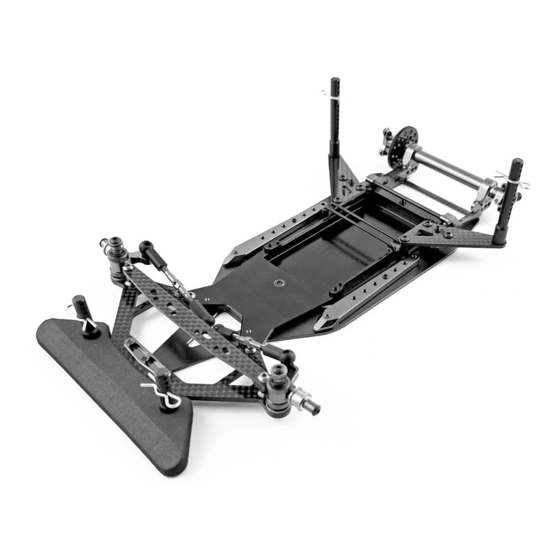
- Page 1 A12WC 1/12-SCALE ELECTRIC ON-ROAD CAR INSTRUCTION MANUAL...
-
Page 2: Assembly Notes
This kit is a radio controlled model racing product and could cause personal injury or harm if not used as intended. The A12WC car is designed for use on r/c car race tracks; it should not be used in areas primarily intended for use by the general public. - Page 3 STEP 1 AM1206 C1205-X SH1.5W SH1.5W Note: C1204 The “X” engraving should be facing upwards! SF3X10 SF3X10 Note: SH1.5W is 7.4x3x1.5mm alloy spacer. STEP 2 SS3X5 AM1205.1 AM1205.1 SS3X5 AM1205.1 SS3X5 Note: SS3X5 screws should be just touching the AM1204WC. Use low strength Thread Locker (blue) for for SS3X5 screws.
- Page 4 STEP 4 ST1248 Use a 3mm hex driver to screw ST1248. Apply some low strength thread locker to the thread. AM1203WC ST1248 ST1248 Screw ST1248 flush in AM1203WC from lower side. STEP 5 Note: The kit’s rollcenter set is LRC (Low Roll Center) set. Try to install the joints without Optional rollcenter sets are available (not kit included): ST1255...
- Page 5 STEP 6 STEP 7 Note: Add ~0,3 g of 50 000...100 000 cst silicone oil Note: Add a bit of silicone oil into groove of ST1202. into cavity of ST1204 damper case. We recommend 100 000 cst silicone oil as the base setup. Keep ST1204 upright for several minutes until all oil reaches the bottom of the cavity.
- Page 6 STEP 9 Repeat the STEPS 5,6,7 for other side of ST1204 and check that both ST1202 rotors reached the desirable position (flush with the ST1204 face) Note: These faces of ST1204 and ST1202 should coincide. STEP 10 SB3X5 SB3X5 Note: SS3X10 set screw is used for adjusting of the rear downstop. An exact position of this SS3X10 screw will be set later during setup SS3X10 of the car.
- Page 7 STEP 11 ST1201 3mm Ball Stud ST1201 AM1207.1 ST1203.1 ST1201 AM1202.1 STEP 12 ST112 x2 ST112 x2 Note the shoulder Note: ST1201 ball studs should be placed into slots of ST1202 rotors. ST112...
- Page 8 STEP 13 Note: Assortment of SH shims is used for setting of the desired Rear Ride Height - RRH. Short and +1mm longer wheelbase settings are possible. Note position of SS3X5 screws. AT1203 SH0.25 SH0.5 SS3X5 SH1.0 Short wheel base SS3X5 SH0.25 SH0.5...
- Page 9 STEP 15 1,5mm hex driver Note: ST1208-C4AL steering block posts provide 4 deg caster. or optional Optional ST1208-C5 posts provide 5 deg caster. RHG 4.2 probe Optional ST1208-C2 posts provide 2 deg caster. Optional ST1208-C6 posts provide 6 deg caster. ST1208-C4AL AT1206 The tip of 1,5mm hex driver or optional...
- Page 10 STEP 16 AT1201 AT1201 note orientation! note orientation! DT1202 DT1202 ST24 ST24 SH1.0 SH1.0 SH0.5 SH0.5 AT1204-X AT1204-X OR155SI OR155SI SH0.1 x 0...2 SH0.1 x 0...2 note orientation! note orientation! DT1202 DT1202 If less damping is required remove OR155SI AT1201 o-rings and use only thick silicone grease AT1201 inside the AT1204-X steering block and...
- Page 11 STEP 18 Installation of the standard mini servo. Installation of the SANWA SRG servo. SB3X5AL C1201-X SH1.0 SB3X5AL SB3X5AL C1201-X SB3X5AL SH1.0 AT1202 ST24-4.0 x2 SH0.25 SB3X6 ST24-4.0 x2 SANWA SRG servo (not included!) AT1202 SH0.25 Servosaver (not included!) SB3X6 Mini servo (not included!) Up to 35x30x15mm mini Servosaver (not included!)
- Page 12 STEP 21 ST1211 SB3X4 SPR12S0.5 C1203.1 Snap the spring on the groove of ST1211 retainer and rotate the spring to find the mutual DT1213 angular position that provides a perfect alignment of the spring and retainer. Using the outer position of the ST1211 retainer provides an increase in the Use this hole for the side spring...
- Page 13 Note: Use thin double sided tape to secure STEP 2 P1215 foam bumper on C1204 bumper plate. P1215 P14-2 P14-2 P14-2 P14-2 SB3X10 Motor (not included) SB3X10 SF3X10 SF3X10 SH0.25 SH0.25 SB3X10 SB3X8 STEP 24 Note: Use OR91 9x1mm o-ring with the thick spur gears.
- Page 14 STEP 25 SC25X8 AT1207-X SH12R3.5 SH12R2.0 SH12R0.5 SC25X8 Note: The second SC25X8 M2.5x8 screw is used for perfect axle balancing of the left wheel hub. SH12R0.5 SH12R2.0 Note: The set of SH12R*** spacers shown ensures correct initial centering of the rear axle. Carbon Spool set CS-1 (optional).
- Page 15 STEP 26 STEP 27 Note: Combination of SH12F0.5 spacers on both sides of the front wheel is used for the front width adjustment. Front 1/12 wheel (not included) B156 B156 SH12F0.5 SB3X5 Pinion gear (not included) Rear 1/12 wheel (not included) SC3X5 x3 SC3X6 x3 Note:The sum of the 64P spur+pinion teeth should...
- Page 16 When using big tires, you will need to use shims under the C1205 to obtain the desired ride height. Placing shims under the steering block will not be sufficient to lower the ride height to proper height with larger tire sizes, so please use this additional method of adding shims under the C1205-X SH0.25...SH1.0 x7...
- Page 17 DG1X Setting of the Rear Downstop (RD). Rear Downstop (RD) value in the A12WC car indicates how far the motor pod can drop below the bottom surface of the rear damper. Adjusting of SS3X10 set screw position - Downstop Screw Depth (DSD) is used for setting of the rear downstop RD.
- Page 18 Optional roll centers sets. ELRC Set ST1205 - 2 pcs ST1209-M - 1 pcs ST1209-L - 1 pcs ST1224 ST1224 - 2 pcs ST1225 SH1.5W ST1225 - 2 pcs SH1.0 SH0.25 ST1224 ST1225 AM1206 ST1205 ST1205 ST1209-L ST1209-M C1205-X SH1.5W SH1.0 SH0.25 ST1248...
-
Page 19: Setup Sheet
SETUP SHEET A12WC VERSION 1.0 DATE TEMPERATURE AIR / TRACK °C °C NAME COUNTRY ASPHALT OUTDOOR INDOOR CARPET TRACK CONDITION BUMPY FLAT RACE TECHNICAL MIX ED FAST TRACTION TRACK MEDIUM HIGH SERVO PLATE STEERING HUB POSTS SUSPENSION PLATE ST1208-C4AL ST1208-C4S... - Page 20 Spare parts Parts # Description Parts # Description AM1202 .1 SPR12S0.5 Side Spring C0.5 Motor Mount Body Clip AM1203 WC SPR05 Battery Plate B156 3/16x5/16x1/8 Flanged Bearing AM1204 WC Chassis Plate B168 1/4x3/8x1/8 Flanged Bearing AM1205 .1 Side Beam SH12S-0.2 Spring Shim 0.2mm AM1206 Front Nut...
- Page 21 WWW.AWESOMATIX.COM UAB “AWESOMATIX” Email: support@awesomatix.com All rights reserved. Copyright UAB “Awesomatix” 2024.
Need help?
Do you have a question about the A12WC and is the answer not in the manual?
Questions and answers