Advertisement
Quick Links
Advertisement

Related Manuals for Awesomatix A700


Summary of Contents for Awesomatix A700
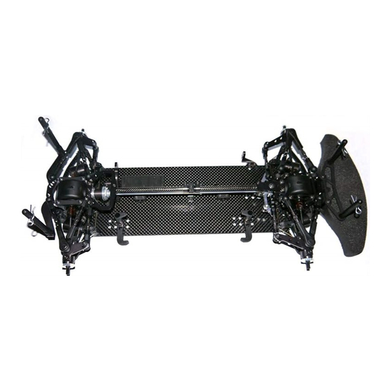
- Page 1 A A 700 1/10-SCALE TOURING CAR INSTRUCTION MANUAL...
- Page 2 Before starting each build-stage check that you have the right quantity and size of items for the build-stage. To assist you with the assembly of your A700 car we have included full-size images of all the small hardware parts laid out so that you can place items on top of the images to check they are the correct size/length.
- Page 3 LET’S START Four main configurations of the A700 car layout are possible. Some building steps have different variants depending on a desirable configuration. Motor layout - transverse Motor layout - transverse Servo location - right side Servo location - left side...
-
Page 4: Table Of Contents
STEP 1 SB3X8 ST03 ST03 SB3X8 SH1.0 SB3X5 SB3X5 SH1.0 SH1.75 AM14 SH1.0 SH1.0 SH0.5 SB3X8 AT21 AT21 AM06 AM06 ST03 ST03 Notes: 1. Apply a thin CA glue on all carbon parts edges to protect and seal them. 2. The last turns of the lower ST03 Ball Studs are tight. - Page 5 STEP 2 Assembling/disassembling method ST01 Apply Joint Grease to the rubbing surfaces. ST16 PIN01 ST17 ST16 SPR07 PIN01 ST13 ST11 ST10 ST11 1. Insert a 2.5mm flat screwdriver tip into ST17 Universal Ring slot, bend of You can use optional the lug and turn screwdriver through 90 deg.
- Page 6 STEP 3 ST11 ST02 PIN01 ST16 ST11 You can use optional ST11 Bushings R or SPR07 ST14 ST12 Bushings S instead Apply Joint Grease to of P08 C-Drives also. the rubbing surfaces. Assembling/disassembling method 1. Unclamp ST02 Rear Axle a bit. 2.
- Page 7 STEP 4 B106RS AT15 B106RS SH0.1 AT13 B106RS B106RS AT13 B106RS MR106RS Bearing x8 AT15 Bearing Spacer x2 SH0.1 6x8x0.1mm Shim AT13 Wheel Hex P16 Lock Ring STEP 4 FINISHED Make 2 Rear. Note: Rear Universals may be a bit tight at this stage. But do not worry.
- Page 8 STEP 5 Note: Apply thin CA glue on all carbon parts edges to protect and seal them. SB25X8 SB25X8 Note: Don’t overtighten SB25X8 Screws to avoid ST03 Ball Stud binding. Achieve the free action of the ball joint with a minimal backlash. SB2.5X8 SB25X8 M2.5x8 Button Head Screw x8 C04 Suspension Arm x4...
-
Page 9: Sh1.0
STEP 6 SS3X5 AT21 AT21 AT21 AT21 AT21 SH0.5 SH0.5 AT21 AT21 Note: Make like this. SH0.5 AT21 SH0.5 FRONT REAR SS3X5 SF3X8 SS3X5 SF3X8 SS3X5 SF3X8 SF3X8 SF3X8 SF3X8 SF3X8 SF3X8 SS3X5 Note: Apply thin CA glue on all C01 Lower Deck edges to protect and seal them. Insert P06 Downstop Collars and use CA glue for fixing them before SS3x5 screwing. -
Page 10: Step 8
STEP 8 STEP 7 Attention! The deflected tips of Sway Bar should be directed downwards. Do not overtighten SS3X4 Screws to allow SB10..SB13 Sway Bar to move a little. SS3X4 SS3X4 SS3X4 SS3X4 SF3X8 SF3X8 STEP 8 (cont’d) Use bigger hole for SB12 and SB13 Sway Bars. - Page 11 STEP 9 SPR03 Note: Initial position of RHS Ride Height Screw. Don’t tighten up SRS Spring Rating Screw at this stage. STEP 9 (cont’d) SPR01 ST05 Spring Rating Screw x4 STD Damper Right x2 Ride Height Screw STD Damper Left SPR03 Shock Pointer SPR01 Shock Spring STEPS 9...
-
Page 12: Sh1.75
STEP 10 AM08 SH1.75 SH1.75 SF3X10 SF3X10 SF3X10 Note: Lay down Dampers SF3X10 M3x10 Flat Head Screw into grooves on the Chassis. SH1.75 6x3x1.75mm Spacer (Black) x4 AM08 Shocks Holder STEP 10 (cont’d) STEPS 10 FINISHED Mount Front and Rear Shocks. snap... - Page 13 STEP 11 AT21 AT21 AT21 AT21 SH1.0 SH1.0 SH1.0 SH1.0 SH1.0 SH1.0 SH1.75 SH1.75 For right-side servo location AM09 For left-side servo location SS3x12 SS3x12 SS3x12 AM09 SS3x12 SS3X12 M3x12 Set Screw AT21 Pivot Ball SH1.0 6x3x1.0mm Spacer (Gray) AM09 Steering Rod x1 STEP 12 SH1.75 6x3x1.75mm Spacer (Black) x1 AM10 Steering Plate x1...
-
Page 14: Sh0.5
STEP 14 Note: Use SH0.1 shims for further fine adjustment of bevel gears clearance. B106RS Snap SPR06 Wire Ring AM01 on G03 Bevel Gear B106RS SH0.1 SPR06 B106RS MR106RS Bearing AM01 Gear Box SH0.5 6x3x0.5mm Spacer (Silver) x2 G03 25T Bevel Gear x1 SH0.1 6x8x0.1mm Shim SPR06 Wire Ring STEP 15... - Page 15 STEP 16 STEP 17 SH0.1 AM01 B106RS Note: Use SH0.1 shims for B106RS MR106RS Bearing AM01 Gear Box further fine adjustment of bevel gears clearance. G03 25T Bevel Gear x1 SH0.1 6x8x0.1mm Shim Gear Tube STEP 18 SF3X6 M3x6 Flat Head Screw x10 P10 Diff Cover x2 STEP 19 FRONT...
- Page 16 STEP 20 For longitudinal motor layout For transverse motor layout AT20 PIN02 B106RS SS3X4 PIN02 SS3X4 G02 27T Bevel Gear PIN02 ~0.7mm B106RS MR106RS Bearing AT20 Spur Axle B84RS MR84RS Bearing ST06 Gear Axle SF3X5 M3x5 Flat Head Screw 22T Bevel Gear x1 ~0.7mm SB3X5 M3x5 Button Head Screw x1 AM13 Spur Holder...
- Page 17 STEP 23 SF3X6 x5 For transverse motor layout SF3X6 x4 For longitudinal motor layout SF3X6 M3x6 Flat Head Screw x6 / x4 STEP 24 For transverse motor layout SF3X6...
- Page 18 STEP 25 STEP 26 ST20 Note: At first cut off all 4 protruding tips of OR05 P17 Plastic Cross with a sharp knife. B74RS SH0.1 OR05 B74RS OR03 AT23 AT24 B106RS ST07 B106RS ST07 B106RS MR106RS Bearing AT23 GD Case1 GD Case2 MR85 Bearing ST20 GD Shaft...
- Page 19 STEP 29 (optional) STEP 29 FINISHED Assembling of BD1 Ball Diff Set (not included). This ball differential is sealed and can be filled by silicone oil of the proper viscosity. So it is no need to apply special diff greases in this case. Apply appropriate diff greases only if TB38M you don’t want to fill this diff by oil.
- Page 20 STEP 32 (optional) STEP 32 FINISHED DT06 OR02 DT06 B74RS OR02 B74RS Put DT06 Diff Stops on OR04 ST07 Outdrives ends. AT02 B106RS AT01 ST07 B106RS ST07 B106RS MR106RS Bearing x2 AT01 Diff Case1 B74RS MR74RS Bearing AT02 Diff Case2 STEP 33 (optional) 14mm O-Ring DT06...
- Page 21 STEP 35 Press on ST07 Outdrive and rotate it to enter into meshing with the AT03 Spool Axle. Then snap each Outdrive completely. There are two lock rings inside the Spool Axle for fixation of the Outdrives. ST07 B106RS AT03 DT02 B106RS ST07...
- Page 22 STEP 37 Make 2 front rods P13-1 P13-2 Make 4 snap Make 2 rear rods P13-1 P13-3 P13-3 P13-3 AT14 AT14 Front left Front right upper arm upper arm P13-2 P13-2 AT14 AT14 P13-1 Ball End 14mm x4 Ball Joint1 P13-2 Ball End 19mm x6 Ball Joint2 P13-3 Ball End 22mm x6...
-
Page 23: Sh1.0 6X3X1Mm Spacer (Gray)
STEP 38 FOR REAR FOR FRONT AT21 AT21 AT21 SH1.75 AT21 SH1.75 SH1.0 AT21 SH1.75 AT21 SH1.75 SH1.75 SH1.0 AT21 SH1.75 AT21 SH1.75 SH1.75 SH1.0 SH1.75 SH1.75 SH1.75 SH1.0 SH1.75 AM19 AM19 AM19 AM19 SS3X14 SS3X14 SB3X10 AT21 SB3X10 SB3X10 AT21 SB3X10 SB3X10... - Page 24 STEP 41 STEP 42 B84RS AM11 SB3X6 SB3X6 B84RS SF3X6 SF3X6 SB3X6 M3x6 Button Head Screw x2 AM11 Tower STEP 43 B84RS MR84RS Bearing AT12 Spur Nut SF3X6 M3x6 Flat Head Screw AT04 Main Shaft x1 Note: Use 12mm wrench for AT12 Nut tightening. Spur gears (not included): up to 104T/64p (77T/48p) for transverse motor up to 98T/64p (73T/48p) for longitudinal motor.
- Page 25 STEP 44 (cont’d) STEP 44 FINISHED snap AT04 STEP 45 For transverse motor layout Note: Cut motor shaft for minimal possible lateral motor displacement. Otherwise use additional shims between AM04 Motor Mount and AM02 Rear Bar or motor. Motor (not included) SF3X10 SF3X10 Use SH0.5 - SH1.75 shims for motors...
- Page 26 STEP 46 FINISHED Note: Use long 2.0mm ball end hex driver to reach lower SB3X10 motor screw as shown here. For longitudinal motor layout STEP 47 P14-4 P14-4 SB3X6 SB3X6 P14-4 P14-4 SPR05 P14-3 SPR05 SB25X8 SPR05 P14-3 SPR05 P14-2 AT22 P14-2 AT22...
- Page 27 STEP 49 Select Servo Saver Horn (SS01-1 or SS01-2) according to the type of servo you use. SS01-1, SS01-2 SS01-3 SB3X6 SS01-3 SS01-1 SS01-2 SS01-4 AT21 Attach Servo Saver Springs SS01-5 as shown. AM16 SB3X6 M3x8 Button Head Screw x1 SS01-1 Servo Saver Horn F x1 SH0.5 6x3x0.5mm Spacer (Silver) x4 SS01-2 Servo Saver Horn S x1...
- Page 28 STEP 51 Cut off the tip of this Ball End to size specified. ST21 P13-1 P13-1 P13-1 Ball End 14mm SF3X5 M3x5 Flat Head Screw x4 STEP 52 Low-profile servo left-side mounting is shown. ST21 Servo Rod Note: Recommended length of optional servo arm snap is17,5-18,5mm.
- Page 29 STEP 53 SB3X6 Note: Apply thin CA glue on all carbon SB3X8 parts edges to protect and seal them. SB3X8 SB3X8 SB3X8 For longitudinal motor layout SH1.0 x4 ST09 For transverse motor layout AT06 SB3X6 SB3X8 SB3X8 SB3X8 SB3X6 SB3X8 SH1.0 x4 ST09 FLAT BOARD...
- Page 30 CHASSIS FLEX SETTING TECHNIQUE CHASSIS For the softest setting use one central SB3X6 screw only. To increase front flex remove these SB3X6 screws. It is possible both for front and rear of the chassis. SB3X6 ST09 To increase rear flex remove some SF3X6 screws To increase rear flex remove some SF3X6 screws.
- Page 31 AM15 STEP 54 BATTERY MOUNTING TECHNIQUE AM12 AM15 AT12 AM12 AM12 AM12 SF3X10 SF3X10 SF3X10 M3x10 Flat Head Screw x4 SF3X10 AM15 Battery Nut SF3X10 AM12 Battery Holder Use battery displacement for left-to-right and front-to-rear weight balance adjustment without additional lead weight. Battery fixing system allows up to 11mm lateral offset for battery, 4 front-to-rear battery positions at left-side servo and one front-to-rear position at right-side servo.
- Page 32 BATTERY MOUNTING TECHNIQUE (cont’d) AM12 Battery installation at the right-side servo. SF3X6 AM15 SF3X6 AM15 SF3X6 Transverse battery taping is possible. This method reduces the influence of the battery on the car flex. SF/SS Screw Use SF/SS Screw on Motor Mount as adjustable inner battery catch at R2 position.
- Page 33 BATTERY MOUNTING TECHNIQUE (cont’d) NiMH battery installation technique.
- Page 34 STEP 55 FINAL ASSEMBLY Install: speed controller (not included), receiver (not included), transponder (not included) battery (not included) wheels (not included) Transverse motor layout Speed controller Battery Transponder Longitudinal motor layout Speed controller Battery Transponder Note: Change spur gear without dismounting of C03 Top Deck ! Take out AT04 Main Shaft first only.
- Page 35 SUSPENSION SETTING TECHNIQUE Camber adjustment rule: Simultaneous both upper rods Caster adjustment rule: Simultaneous front upper rod 0.5mm shortening (1/2 turn of both turnbuсkles) adds 1.0° 0.5mm elongation and rear upper rod 0.5mm shortening of camber angle at constant caster. adds 2.5°...
- Page 36 SHOCK SETTING TECHNIQUE Attention! These Shocks allow to adjust the Damping and Spring rates without replacement of the shock’s fluid and spring. 1. Damping and Shock Spring rate setting Increase A distance (slide Shock outward) to increase Damping and Spring rates simultaneously and concordantly to each other.
- Page 37 DAMPER ACTION MODE CHANGE There are two Damper Action Modes: symmetric and asymmetric modes. At symmetric Damper Action Mode the compression and rebound strokes are equivalent. At asymmetric Damper Action Mode the compression stroke is softer than rebound stroke. Symmetric Damper Action Mode is factory-set. To change this mode: 1.
- Page 38 LONG UPPER ARM SET (OPTIONAL) REAR AT25 AT25 SB3X6 SB3X6 AT25 AT25 SS3x8 SS3x14 SS3x8 SB3X5 SS3x14 SB3X5 AM18 SB3X6 M3x6 Button Head Screw x2 SB3X5 M3x5 Button Head Screw x2 SS3X8 Set Screw SS3X14 Set Screw ST09 Upper Collar AM18 Front Holder AT25 Turnbuckle Long Use ST09 collars at softest chassis flex setting.
- Page 39 FINAL DRIVE RATIO CHART )25 75$169(56( 02725 /$<287 '5,9( 75$,1 5$7,2 3,7&+ 6385 *($5 3,7&+ 6385 *($5...
- Page 40 FINAL DRIVE RATIO CHART (cont’d) )25 /21*,78',1$/ 02725 /$<287 '5,9( 75$,1 5$7,2 3,7&+ 6385 *($5 3,7&+ 6385 *($5...
- Page 42 tandard initial setup...
- Page 43 Standard Spare Parts Parts# Description Parts# Description AM01 Gear Box STD Damper Left AM02 Rear Bar STD Damper Right AM03 Motor Mount L SPR01 STD Shock Spring AM04 Motor Mount T SPR02 Shock Rod Guide AM05 Rear Holder SPR03 Shock Pointer AM06 Steering Block SPR05...
- Page 44 WWW.AWESOMATIX.COM AWESOMATIX INNOVATIONS LLP PARTNERSHIP No. OC353017 RUSSIA - UNITED KINGDOM Email: support@awesomatix.com All rights reserved. Copyright Awesomatix Innovations LLP 2011.
Need help?
Do you have a question about the A700 and is the answer not in the manual?
Questions and answers