Table of Contents
Advertisement
Quick Links
Advertisement
Table of Contents

Related Manuals for Awesomatix A800X


Summary of Contents for Awesomatix A800X
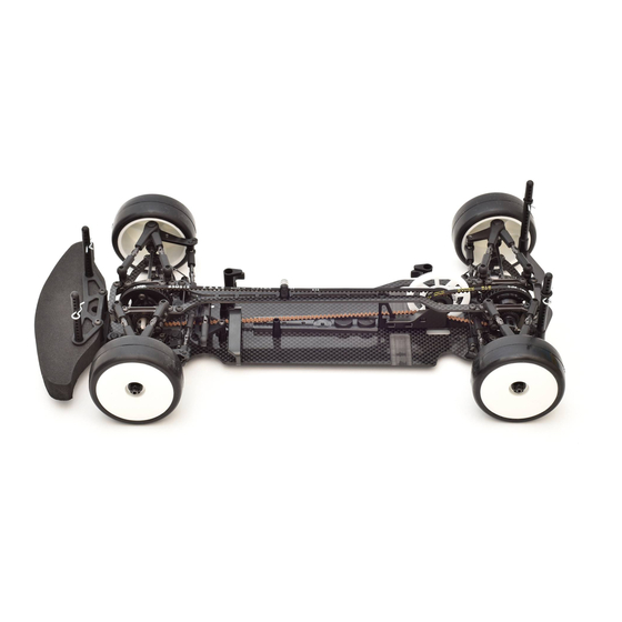
- Page 1 A800X 1/10-SCALE TOURING CAR INSTRUCTION MANUAL...
- Page 2 Awesomatix Innovations accept no responsibility for any injuries caused by making or using this kit. Due to policy of continuous product development the exact specifications of the kit may vary. Awesomatix Innovations do reserve all rights to change any specifications without prior notice. All rights reserved. ASSEMBLY NOTES Before starting each build-stage check that you have the right quantity and size of items for the build-stage.
- Page 3 STEP 1 ST03 ST03 SB3X5 SH1.75 SB3X5 AM14A SH1.75 SH1.75 AM23-1 SH1.75 SH1.75 SB3X8 SH1.0 SH1.0 ST24 ST24 AM06WL AM06WL ST03 ST03 ST03 ST24 Note: The last turns of the lower ST03 Ball Studs and SB3X5 screws can be tight. Screw them with force. Note the difference between ST03 and ST24 Ball Studs! SB3X5...
- Page 4 STEP 2 ST38 ST01 Apply Joint Grease to the rubbing surfaces. ST16 PIN01 ST17 -1 ST16 SPR07 PIN01 ST38 ST12 ST11 ST13 ST11 Attention! ST12 Note the mutual orientation of ST16 at screwing of ST38. The pins of both ST16 should be parallel to each other. You can use optional ST10 The recommended wrench for screwing of ST38 is...
- Page 5 STEP 3 ST02 ST12 PIN01 ST16 ST12 You can use optional ST12 Bushings S or ST14 SPR07 UB1 Ball Bearings set Apply Joint Grease to instead of ST11 Bushing R. the rubbing surfaces. ST11 Assembling/disassembling method 1. Unclamp ST02 Rear Axle a bit. 2.
- Page 6 STEP 4 B106RS B106RS B106RS B106RS AT13 SC2X6 SC2X6 AT13 B106RS MR106RS Bearing AT13 Wheel Hex SC2X6 M2x6 Cap Head Screw x4 STEP 4 P16 Lock Ring FINISHED Make 2 Rear. Make 2 Front. Note: Press P16 Lock Ring on the Axle to fix it. Note: Rear Universals may be a bit tight at this For disassembly hit to the end face of the Axle or stage.
- Page 7 Rebuildable Damper Set Note: Every A800X kit includes four factory assembled and oil filled D2.2 Rebuildable Dampers. D2.2 damper allows for both dampening adjustment via thicker silicon oil, and consistent performance since the racer can rebuild the shock. The factory assembled and oil filled D2.2 Rebuildable Dampers come with 500 cst pure silicone oil inside.
- Page 8 STEP 6 SPR02X SC2X6 SPR03 D2.2 SS3X3 AM17XR STEP 6 Attention! After installation of SPR02X rotate the complete D2.2 damper within AM17XR/L until the maximum up travel is reached and secure SC2X6 screw in the AM17X/RL after that. (cont’d) At the max up travel position the SPR02X should touch the stopper on AM17X/RL !!! Up travel position of SPR02X.
- Page 9 STEP 7 Note: C01B-X Carbon Lower Deck is used in A800X kit C01B-XA Alloy Lower Deck is used in A800XA kit C01B-XAH Alloy Hard Lower deck is used in A800XAH kit AT21 x4 AT21 x4 FRONT SH1.0 x4 SH1.0 x4 SF3X6 x4 Don’t tighten SF3X6 screws...
- Page 10 STEP 9 STEP 10 WA02 WA02 ST31-1 WA02 WA02 ST31-1 WA03 WA03 OR05M OR05M SC2X4 x3 Thread Lock AT123B P138 B106RS OR05M OR06 OR13 ST23 OR13 Attention! PIN02 Don’t overtighten SC2X4 screws. Such overtigh t ening AT123B GD2B Case1 B106RS MR106RS Bearing AT124B deforms P138 Pulley.
- Page 11 STEP 13 SF3X8 Thread Lock ST37 B106RS B106RS AT03BX ST37 SF3X8 P138S SB3X5 x3 B106RS MR106RS Bearing ST37 Spool Outdrive SF3X8 M3x8 Flat Head Screw AT03BX Spool Axle SB3X5 M3x5 Button Head Screw x3 P138S Spool38T Pulley x1 STEP 13 FINISHED Note the correct orientation of AT03B X Axle regarding to P138 S Pulley.
- Page 12 STEP 15 SB3X8 SB3X8 AM88L SB3X8 AM88L SB3X8 AM88R Attention! AM88R Don’t tighten SB3X8 FRONT screws on this stage. SB3X8 M3x6 Button Head Screw x4 AM88R Shock Holder R REAR AM88L Shock Holder L SB3X6 M3x6 Button Head Screw x1 AT120 20T Alloy Pulley AT62 Spur Holder...
- Page 13 STEP 18 Note: Remove the burrs on the straight AT21S edges of DT12 bushings to avoid binding SB3X5 x2 of DT12 in the AM86 steering plate slot. SS3X3 x2 AT71 DT13 x2 SB3X5 ST24 x2 AM86 Adjust the minimal possible vertical play of AT71 steering rack via two lower SB3X5 screws and tighten two upper DT12 x2...
- Page 14 STEP 20 SB3X6 x2 SB3X6 x4 B63SS x2 SB3X8 ST019 SB3X6 x2 ST55 SC2X4 SB3X6 x4 C27X AM05-2 C27X Top Deck Top Stiffener Belt Tensioner x1 AM05-2 Rear Holder SC2X4 M2x4 Cap Head Screw SB3X6 M3x6 Button Head Screw x12 ST55 ST55 SB3X8 M3x8 Button Head Screw x1...
- Page 15 STEP 23 STEP 23 FINISHED snap ST05L ST05L Shock Rod STEP 24 P12X P12X P12X P12X SS3X5 SS3X5 SF3X8 SF3X8 SS3X5 SS3X5 SF3X8 SF3X8 SF3X8 M3x8 Flat head Screw SS3X5 M3x5 Set Screw P12X Sway Bar Holder...
- Page 16 STEP 25 Attention! The deflected tips of Sway Bar should be directed downwards. SWB10...SWB12 Note: SS3X3 SWB12 - two strips Note: SWB11 - one strip Don’t tighten SS3X3 Set Screws at this stage. SWB10 - no strip SS3X3 AT142 B63SS B63SS AT142 SWB10...SWB12...
- Page 17 8,3 mm STEP 26 Servo rod P13-4 AT14 P13-4 8,0 mm Servo rod for AS-701L servo Make 4 snap P13-4 AT14 P13-4 17,6 mm Make 2 rear rods AT14 P13-4 P13-4 20,7 mm 20,7 mm Front left rod Front right rod AT25 AT25 P13-4...
- Page 18 STEP 27 Note: Use the appropriate combination of SB3X10 SH spacers for sufficient gap between SB3X10 battery and P25 Clamps. AT12 BATTERY SH0.5...SH1.75 SH0.5...SH1.75 SH0.5...SH1.0 AM15-1 AM15-3 AM15-3 SF3X6 SF3X6 SF3X10 x2 SF3X10 x2 Battery Holders adjustment: SF3X10 M3x10 Flat Head Screw P23 Outer Battery Holder Choose the desirable battery position.
- Page 19 Note: Recommended length of servo arm is 17,5-18,5mm. We highly recommend our P40F and P40K Servo Arms. We also recommend our AS-701L Brushless Low-Profile Car Servo. Awesomatix AS-701L servo has an integrated servo holder and can be screwed to the chassis. directly.
-
Page 20: Final Assembly
STEP 29 OR06 OR06 SPR05 OR06 SPR05 OR06 P14-2 SB3X6 SPR05 SPR05 SB3X6 P14-2 P14-5 P14-2 P14-2 P15H P14-1 SF3X8 SF3X8 AM05-2 SB3X8 x2 SF3X8 M3x8 Flat Head Screw x5 P14-1 Lower Bumper P14-2 Body Post SB3X8 M3x8 Button Head Screw x2 P14-5 Upper Bumper x1 SB3X6 M3x6 Button Head Screw x2 P15H... - Page 21 ST17 and P20 Universal Rings (optional) AT22 Rear Body Holder (optional) ST17 ST17 clipped P14-2 AT22 Use the extra clipped SB25X8 1. Insert a 2.5mm flat screwdriver tip P14-2 bars for additional into ST17 Universal Ring slot, bend of support of body’s tail. the lug and turn screwdriver through 90 deg.
- Page 22 SUSPENSION SETTING TECHNIQUE Camber adjustment rule: Simultaneous both upper rods Caster adjustment rule: Simultaneous front upper rod 0.5mm shortening (1/2 turn of both turnbuckles) adds 1.0° 0.5mm elongation and rear upper rod 0.5mm shortening of camber angle at constant caster. adds 2.5°...
- Page 23 SHOCK SETTING TECHNIQUE Attention! These Shocks allow to adjust the Damping and Spring rates without replacement of the shock’s fluid and spring. 1. Damping and Shock Spring rate setting Increase A-distance (slide Shock outward) to increase Damping and Spring rates simultaneously and concordantly to each other.
- Page 24 GRAPHS OF THE SUSPENSION STIFFNESS DEPENDING ON THE POSITION OF THE DAMPER (SIZE A) AND SHOCK SCREW HOLDER (SIZE B) Suspension rate, gF/mm (vertical force / vertical displacement of the wheel) FOR SPR01 SPRINGS A, mm B, mm SRS/RHS Screws arrangement I SRS/RHS Screws arrangement II 15 0 FOR SPR01S SOFT SPRINGS...
- Page 25 FINAL DRIVE RATIO CHART DRIVE TRAIN RATIO IS 1,9 64dp SPUR GEAR SIZE 48dp SPUR GEAR...
- Page 26 PetitRC.com...
-
Page 27: Optional Parts
Belt 189 mm Bando BEL513B Belt 513 mm Bando Arm Ball Cap Damper Guage Set Arm Hasp Sway Bar Joint INS-A800X A800X Instruction Manual Arm Clip STS-A800 A800 Stickers Sheet Shock Screw Holder P12X Sway Bar Holder P13-4 Ball End... - Page 28 WWW.AWESOMATIX.COM AWESOMATIX INNOVATIONS Email: support@awesomatix.com All rights reserved. Copyright Awesomatix Innovations 2017.
Need help?
Do you have a question about the A800X and is the answer not in the manual?
Questions and answers