Table of Contents
Advertisement
Advertisement
Table of Contents

Related Manuals for Awesomatix A800FX


Summary of Contents for Awesomatix A800FX
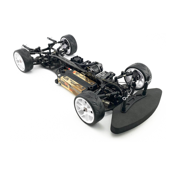
- Page 1 A800FX 1/10-SCALE FRONT-WHEEL DRIVE TOURING CAR INSTRUCTION MANUAL...
- Page 2 You can find the useful tips and pictures of A800FX assembling on the Internet site: http://site.petitrc.com/reglages/awesomatix/SetupSheetsAwesomatixA800.html...
- Page 3 STEP 1 AT21 ST03 ST03 SH1.0 SB3X5 SH1.75 SB3X5 AM14FX SH1.75 SH1.75 AM23-1 SH1.75 SH1.75 SB3X6 SH1.0 SH1.0 ST24 ST24 AM06WL AM06WL ST03 ST03 ST03 ST24 Note: The last turns of the lower ST03 Ball Studs and SB3X5 screws can be tight. Screw them with force. Note the difference between ST03 and ST24 Ball Studs! SB3X5...
- Page 4 STEP 2 Apply Joint Grease to ST38 the rubbing surfaces. ST01 Thread Lock ST16 PIN01 ST17 -1 ST16 SPR07 ST113 PIN01 B415 ST38 ST116 PIN01 Attention! B415 Note the mutual orientation of ST16 at screwing of ST38. SPR07 The pins of both ST16 should be parallel to each other. The recommended wrench for screwing of ST38 is 3/8 US standard wrench ( ~ 9,53 mm).
- Page 5 STEP 3 AT13FX B106RS B106RS B106RS B106RS SB3X4F SC2X6 AT13 SC2X6 Wheel Hex B106RS MR106RS Bearing AT13 AT13FX Wheel Hex SC2X6 M2x6 Cap Head Screw x4 STEP 3 Lock Ring SB3X4F Flanged Screw x2 FINISHED Make 2 Rear. Make 2 Front. Note: Snap P16 Lock Ring onto the groove of the front axle.
- Page 6 Rebuildable Damper Set Note: Every A800FX kit includes four factory assembled and oil filled D2.2 Rebuildable Dampers. D2.2 damper allows for both dampening adjustment via thicker silicon oil, and consistent performance since the racer can rebuild the shock. The factory assembled and oil filled D2.2 Rebuildable Dampers come with 500 cst pure silicone oil inside.
- Page 7 Note: DIN914 M3X3 screw should be installed only in case of DRSS - Dual Rate Spring System function want to be used. More info about DRSS can be found on the P09X product page of the http://shop.awesomatix.com webshop. AM17XR Damper Holder Right...
- Page 8 STEP 6 Note: C01FXC Carbon Lower Deck is used in A800FXC kit C01FXA Alloy Lower Deck is used in A800FXA kit AT21 x4 AT21 x4 FRONT SH1.0 x4 SH1.0 x4 SF3X6 x4 SF3X6 x4 Don’t tighten SF3X6 screws under AT21 balls at this stage. REAR SF3X6 M3x6 Flat Head Screw x8 P03 Arm Ball Cap...
- Page 9 STEP 8 STEP 9 WA02 WA02 ST31-1 WA02 WA02 P46R P46R ST31-1 WA03 WA03 OR05V OR05V SC2X4 x3 Thread Lock AT123B P138 B106RS OR05V OR06 OR13 ST23X OR13 Attention! PIN02 Don’t overtighten SC2X4 screws. Such overtigh t ening AT123B GD2B Case1 B106RS MR106RS Bearing AT124B deforms P138 Pulley.
- Page 10 STEP 12 AM08L-FX SB3X8 SH0.5 SH1.75 AM88L SH1.75 SB3X8 AM88R Attention! Don’t tighten SB3X8 REAR FRONT screws on this stage. SF3X10 SB3X8 M3x8 Button Head Screw Attention! Don’t tighten SF3X10 screw on this stage. SF3X10 M3x10 Flat Head Screw SH1.75 6x3x1.75mm Spacer (black) x2 STEP 13 SH0.5 6x3x0.5mm Spacer (silver) BEL225B...
- Page 11 STEP 15 ST152 ST70 x2 ST24 ST24 ST24 Lubricate the thread of ST24 before screwing. ST152 SF3X6 x2 SF3X10 M3x10 Flat Head Screw x4 Steering Rack ST152 Steering Holder SF3X6 M3x6 Flat Head Screw ST24 4,8x6mm Ball Stud ST70 Guide Bar STEP 16 SF3X10 x2 SF3X10 x2...
- Page 12 STEP 17 ST24 x4 ST019 SH1.75 x8 Note: Only one of two ST019 screws on C27FX top deck can be installed for increasing of the flex. C107 SB3X5 x4 ST019 ST24M x4 ST019 x2 C107 Note orientation of recess on C107. C27FX SH1.0 x4 SH1.75 x4...
- Page 13 STEP 20 Install four P12X Sway Bar Holders. P12X SF3X8 SS3X4 P12X SF3X8 M3x8 Flat head Screw SS3X4 M3x4 Set Screw SF3X8 SS3X4 P12X Sway Bar Holder STEP 21 Install the front Sway Bar and the rear Sway Bar. Attention! The deflected tips of Sway Bar should be directed downwards.
- Page 14 STEP 23 8,6 mm P13-4 P13-4 Servo rod AT14 Make 4 snap 15,2 mm Make 2 rear rods P13-4 AT14 P13-4 25,8 mm 25,8 mm Front left rod Front right rod AT25-44 P13-4 P13-4 P13-4 P13-4 AT25-44 P13-4 P13-4 AT14 AT14 Front right Front left...
- Page 15 STEP 24 SB3X10 Install the front and the rear battery holders and the inner battery stoppers. Note: Use the appropriate combination of SH spacers for sufficient gap between battery and P25 Clamps. AT12 SB3X10 BATTERY SH0.5...SH1.75 SH0.5...SH1.75 SH0.5...SH1.0 AM15-3 AM15-3 AM15-1 SF3X6 SH1.75 x3...
- Page 16 STEP25 SH0.5 x2 SB3X5 x2 Servo (not included) AM24-8 SB3X5 SH0.5 SB3X6 AT21 SF3X5 x3 Adjust position of servo on AM24-8 to provide ~0,5mm crearance between servo and lower deck. SB3X5 SB3X6 M3x6 Button Head Screw SF3X5 M3x5 Flat Head Screw SB3X5 M3x5 Button Head Screw AT21 Pivot Ball AM24-8 Servo Holder...
-
Page 17: Final Assembly
OR06 STEP 26 OR06 OR06 SPR05 SB3X8 P14-2 SPR05 SPR05 P14-2 SB3X8 x2 P14-2 SPR05 P14-5 OR06 SH1.75 SH1.75 P15FX P14-2 Note: Some of these ST110 round weights can be extracted ST110 x5 SB3X8 from ST265 and can be installed via holes of the lower deck ST265 behind the battery for more rear... - Page 18 SUSPENSION SETTING TECHNIQUE Camber adjustment rule: Simultaneous both upper rods Caster adjustment rule: Simultaneous front upper rod 0.5mm shortening (1/2 turn of both turnbuckles) adds 1.0° 0.5mm elongation and rear upper rod 0.5mm shortening of camber angle at constant caster. adds 2.5°...
- Page 19 SHOCK SETTING TECHNIQUE Attention! These Shocks allow to adjust the Damping and Spring rates without replacement of the shock’s fluid and spring. 1. Damping and Shock Spring rate setting Increase A-distance (slide Shock outward) to increase Damping and Spring rates simultaneously and concordantly to each other.
- Page 20 GRAPHS OF THE SUSPENSION STIFFNESS DEPENDING ON THE POSITION OF THE DAMPER (SIZE A) AND SHOCK SCREW HOLDER (SIZE B) Suspension rate, gF/mm (vertical force / vertical displacement of the wheel) FOR SPR01 SPRINGS A, mm B, mm SRS/RHS Screws arrangement I SRS/RHS Screws arrangement II 15 0 FOR SPR01S SOFT SPRINGS...
- Page 21 FINAL DRIVE RATIO CHART DRIVE TRAIN RATIO IS 1,9 64dp SPUR GEAR SIZE 1,9 80 99 100 101 102 103 104 105 106 7,19 6,88 6,94 6,59 6,65 6,71 6,31 6,37 6,44 6,50 6,06 6,12 6,18 6,23 6,29 5,82 5,87 5,93 5,99 6,05 6,10 5,64 5,64 5,70 5,76 5,81 5,87 5,92 5,37 5,43 5,48 5,54 5,59 5,65 5,70 5,75 5,17 5,23 5,28 5,33 5,38 5,44 5,49 5,54 5,59...
- Page 22 SETUP SHEET A800FX ° DATE TEMP. C AIR / TRACK NAME ASPHALT OUTDOOR INDOOR CARPET COUNTRY TRACK CONDITION TECHNICAL MIXED FAST RACE TRACTION MEDIUM HIGH TRACK FRONT REAR AM19-2 AT13W AT13W AM19-4X Wide Narrow AT21S AT21S AT21S+0.5 IN AT21S+0.5 IN...
-
Page 23: Optional Parts
M3x8 Flat Head Screw P13-4 Ball End SF3X10 M3x10 Flat Head Screw P14X Bumper Set BEL225B Belt 225 mm Bando P15FX Foam Bumper FWD DG1X Damper Guage Set Lock Ring INS-A800FX A800FX Manual Outer Battery Holder STS-A800FX A800FX Stickers Sheet... - Page 24 WWW.AWESOMATIX.COM UAB “AWESOMATIX” Email: support@awesomatix.com All rights reserved. Copyright UAB “Awesomatix” 2019.
Need help?
Do you have a question about the A800FX and is the answer not in the manual?
Questions and answers