Table of Contents
Advertisement
Quick Links
Advertisement
Table of Contents

Related Manuals for Awesomatix A800FX Evo


Summary of Contents for Awesomatix A800FX Evo
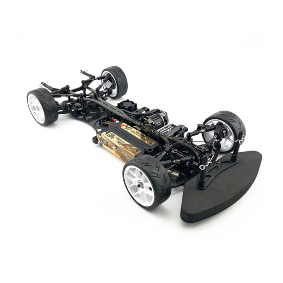
- Page 1 A800FX Evo 1/10-SCALE FRONT-WHEEL DRIVE TOURING CAR INSTRUCTION MANUAL...
- Page 2 You can find the useful tips and pictures of A800FX Evo assembling on the Internet site: https://site.petitrc.com/reglages/awesomatix/setupa800fx/...
- Page 3 STEP 1 AT21ST-A ST03 ST03 SH1.0 SB3X5 SH1.75 SB3X5 AM14FX SH1.75 SH1.75 AM23-1 SH1.75 SH1.75 SB3X6 SH1.0 SH1.0 ST24 ST24 AM06WL AM06WL ST03 ST03 ST03 ST24 Note: The last turns of the lower ST03 Ball Studs and SB3X5 screws can be tight. Screw them with force. Note the difference between ST03 and ST24 Ball Studs! SB3X5 M3x5 Button Head Screw...
- Page 4 STEP 2 Apply Joint Grease to ST38 the rubbing surfaces. ST01 Thread Lock ST16 PIN01 ST17 -1 ST16 SPR07 ST113 PIN01 B415 ST38 ST116 PIN01 Attention! B415 Note the mutual orientation of ST16 at screwing of ST38. SPR07 The pins of both ST16 should be parallel to each other. The recommended wrench for screwing of ST38 is 3/8 US standard wrench ( ~ 9,53 mm).
- Page 5 STEP 3 AT13FX B106RS B106RS B106RS B106RS SB3X4F SC2X6 AT13 SC2X6 Wheel Hex B106RS MR106RS Bearing AT13 AT13FX Wheel Hex SC2X6 M2x6 Cap Head Screw x4 STEP 3 Lock Ring SB3X4F Flanged Screw x2 FINISHED Make 2 Rear. Note: Snap P16 Lock Ring onto the groove of Make 2 Front.
- Page 6 STEP 5 Assembling of the Dampers Note: We recommend to use 5 0 0 cst pure silicone oil for D2.2-S-P dampers of this kit. 1) Stretch and place OR18V o-ring in the groove of the AT40-1 cup. 2) Insert P63 piston into AT41-2 vane cavity. Align the outer face of P63 piston with the outer edge of AT41-2 vane cavity. Keep AT T T 4 4 4 1 1 1 - - - 2 2 2 in vertical position and add a drop of oil into the outer conical hollow of P63 piston to fill this hollow fully.
- Page 7 STEP 6 SC2X6 SPR03 SPR02X P46R D2.2-S-P AM17XL/R AT119 SS3X3 ST69-00 Note: P46R ball should be placed ST69-15 and ST69-25 screw between SRS screw and ST69-00 screw. AM17XR Damper Holder Right SC2X6 M2x6 Ca Head Screw x4 AM17XL Damper Holder Left Spring Rating Screw D2.2-S-P Damper...
- Page 8 STEP 7 Note: C01FXCL Carbon Lower Deck is used in the A800FXC Evo kit C01FXAL Alloy Lower Deck is used in the A800FXA Evo kit AT21ST-A x4 AT21ST-A x4 FRONT SH1.0 x4 SH1.0 x4 Don’t tighten SF3X6 screws SF3X6 x4 SF3X6 x4 under AT21ST-A balls at this stage.
- Page 9 STEP 9 STEP 9 (cont’d) WA02 WA02 ST31-1 WA02 WA02 P46R P46R ST31-1 WA03 WA03 OR05V OR05V SC2X4 x3 Thread Lock AT123B P138 B106RS OR05V OR06 OR13V ST23X OR13V Attention! PIN02 Don’t overtighten SC2X4 screws. Such overtigh t ening AT123B GD2B Case1 B106RS MR106RS Bearing AT124B deforms P138 Pulley.
- Page 10 STEP 12 SB3X8 AM08FX AM88L SH0.5 SH1.75 SH1.75 SB3X8 AM88R Attention! Don’t tighten SB3X8 FRONT screws on this stage. REAR SB3X8 M3x8 Button Head Screw SF3X10 SF3X10 M3x10 Flat Head Screw Attention! Don’t tighten SF3X10 screw on this stage. SH1.75 6x3x1.75mm Spacer (black) x2 STEP 13 SH0.5 6x3x0.5mm Spacer (silver) BEL225B...
- Page 11 STEP 15 C107S Note: Only one of two ST019 screws on C27FX-2 ST019 top deck can be installed for increasing of the flex. SB3X5 x4 ST24M x4 ST019 ST019 x2 Note orientation of C107S SH1.0 x4 recess on C107S. C27FX-2 SH1.75 x4 C27FX-2 Top Deck C107S Front Top Deck...
- Page 12 STEP 17 STEP 18 ST24 x4 SH1.75 x8 snap P07 x2 snap SH1.75 6x3x1.75mm Spacer (black) x8 P07 Arm Clip ST24 4,8x6mm Ball Stud STEP 18 FINISHED Tighten all SF3X6 screws under AT21ST-A pivot balls at this stage. STEP 19 STEP 19 FINISHED Install all four ST05L ST05L Shock Rod...
- Page 13 STEP 20 Install four P12X Sway Bar Holders. P12X P12X SF3X8 SS3X4 SF3X8 M3x8 Flat head Screw SS3X4 SF3X8 SS3X4 M3x4 Set Screw P12X Sway Bar Holder STEP 21 Attention! Install the front Sway Bar The deflected tips of Sway Bar and the rear Sway Bar.
- Page 14 STEP 23 9,7 mm P13-4 P13-4 Servo rod AT14 Make 4 snap 15,5 mm P13-4 P13-4 AT14 Make 2 rear rods 27,6 mm 27,6 mm AT25-44 AT25-44 P13-4 P13-4 P13-4 P13-4 Right steering rod Left steering rod P13-4 P13-4 AT14 AT14 AT14 Turnbuckle AT25 Turnbuckle...
- Page 15 STEP 24 SB3X10 Install the front and the rear battery holders and the inner battery stoppers. Note: Use the appropriate combination of SH spacers for sufficient gap between battery and P25 Clamps. AT12 SB3X10 BATTERY SH0.5...SH1.75 SH0.5...SH1.75 AM15-3 AM15-3 AM15-1 SF3X6 SH1.75 x3 SH1.0...
- Page 16 STEP25 New SBFX (Single Bellcrank) steering system is used for A800FX Evo car. AT21ST-A SB3X6 SH0.5 Servo (not included) SB3X6 SH0.5 Servo horn (not included) Servo rod SB3X6 AM24FX ST24 SF3X5 x2 SH0.5 x2 SB3X6 x2 SH3X5X0.1 AM180FX AT21ST-A x2...
- Page 17 STEP 26 OR06 OR06 OR06 SPR05 P14-2 SPR05 SB3X8 SPR05 P14-2 P14-2 SB3X8 x2 SPR05 SH1.75 OR06 SH1.75 P14-5 P14-2 P15FX SB3X8 ST230 P14-1X AM05-2 SB3X12 M3x12 Button Head Screw P14-1X Lower Bumper P14-2 Body Post SF3X10 M3x10 Flat Head Screw P14-5 UpperBumper SB3X8 M3x8Button Head Screw P15FX Foam Bumper...
- Page 18 REAR STIFFENER AND ADDITIONAL FRONT FLEX OPTION AM30FX SH0.5 x2...6 AM30FX stiffener can be installed via SH0.5 spacers and SF3X6 screws for reducing and adjustment of the car’s rear end flex. Start from two the most front holes of AM30FX SF3X6 x2...6 Up to 6 pcs of SF3X6/SH0.5 can be used for maximal stiffness.
- Page 19 SUSPENSION SETTING TECHNIQUE Camber adjustment rule: Simultaneous both upper rods Caster adjustment rule: Simultaneous front upper rod 0.5mm shortening (1/2 turn of both turnbuckles) adds 1.0° 0.5mm elongation and rear upper rod 0.5mm shortening of camber angle at constant caster. adds 2.5°...
- Page 20 SHOCK SETTING TECHNIQUE Attention! Awesomatix shocks allow to adjust the damping and spring rates without replacement of the shock’s fluid and spring. 1. Damping and suspension spring rate setting Increase A-distance (slide the damper outward) to increase the damping and spring rates simultaneously and concordantly to each other.
- Page 21 GRAPHS OF THE SUSPENSION STIFFNESS DEPENDING ON THE POSITION OF THE DAMPER (SIZE A) AND SHOCK SCREW HOLDER (SIZE B) Suspension rate, gF/mm (vertical force / vertical displacement of the wheel) FOR SPR01 SPRINGS A, mm B, mm SRS/RHS Screws arrangement I SRS/RHS Screws arrangement II 15 0 FOR SPR01S SOFT SPRINGS...
- Page 22 FINAL DRIVE RATIO CHART DRIVE TRAIN RATIO IS 1,9 64dp SPUR GEAR SIZE 1,9 80 99 100 101 102 103 104 105 106 7,19 6,88 6,94 6,59 6,65 6,71 6,31 6,37 6,44 6,50 6,06 6,12 6,18 6,23 6,29 5,82 5,87 5,93 5,99 6,05 6,10 5,64 5,64 5,70 5,76 5,81 5,87 5,92 5,37 5,43 5,48 5,54 5,59 5,65 5,70 5,75 5,17 5,23 5,28 5,33 5,38 5,44 5,49 5,54 5,59...
- Page 23 SERVO ST09 SPUR PINION RATIO STEER TRAVEL IN ST019 AT158 BODY BATTERY AT158 WING RECEIVER RADIO REAR TOP DECK C27FX-2 ESC SETTING FRONT TOP DECK C107S BEST LAPTIME QUALIF./FINAL POSITION Editable setup sheet can be downloaded from: https://site.petitrc.com/ reglages/awesomatix/setupa800fx/ COMMENTS:...
- Page 24 P12X Sway Bar Holder SF3X12 M3x12 Flat Head Screw P13-4 Ball End BEL225B Belt 225 mm Bando P14X Bumper Set DG1X Damper Guage Set P15FX Foam Bumper FWD STS-A800FX A800FX Evo Stickers Sheet Lock Ring Outer Battery Holder Battery Clamp...
- Page 25 WWW.AWESOMATIX.COM UAB “AWESOMATIX” Email: support@awesomatix.com All rights reserved. Copyright UAB “Awesomatix” 2021.
Need help?
Do you have a question about the A800FX Evo and is the answer not in the manual?
Questions and answers