Table of Contents
Advertisement
Quick Links
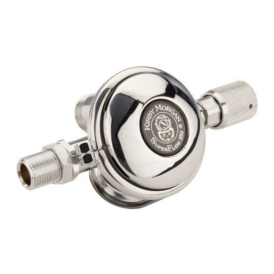
SuperFlow® Regulator
SF-1
SF-1
1.1.1 General Regulator
Information
SF-2
1.1.2 SuperFlow
Regulator Test for Correct
Adjustment, Fully Assembled
SF-2
1.1.3 Inspection of SuperFlow
Regulator Body Interior
SF-4
1.1.4 SuperFlow
Regulator Bias Adjustment
Servicing, Demand Regulator
on the Helmet
SF-5
1.1.5 Reassembly of the
SuperFlow
SF-5
1.1.6 SuperFlow
Regulator Removal from
Helmet
SF-6
SuperFlow
SF-8
SF-10
SuperFlow
1.1 SuperFlow
Demand Regulator
®
1.1.1 General Regulator Information
While the regulator systems on all Kirby Mor-
gan helmets are simple and highly reliable, the
breathing resistance will increase if the demand
regulator on your helmet is not maintained or
adjusted properly. The demand regulator must
receive regular maintenance to assure the best
performance possible. However, in the event the
demand regulator is damaged, there is always a
backup supply of steady flow gas available from
the defogger valve.
For the gas inlet valve and adjustment system to
operate properly, the components in the demand
regulator MUST be in good condition and MUST
be periodically inspected and adjusted.
Five special tools, the inlet valve holder (P/N
525-616), the regulator adjustment wrench (P/N
© MMXXIV Kirby Morgan Dive Systems, Inc. All rights reserved. Document # 240701035
SuperFlow
Contents
®
Demand
®
®
Demand
®
®
Demand
®
®
®
Demand Regulator
®
Regulator
®
SF-16
SF-16
Steady Flows When Pressured
Up: Special Tools Used
SF-19
SF-19
SF-19
SF-20
525-611), the socket wrench (P/N 525-612), the
castle wrench (P/N 525-618), and the regulator
mount nut socket wrench (P/N 525-625) should
be used to work on the SuperFlow
whenever possible.
Disassembly, assembly, and adjustment can be
done without these tools, but the work is much
easier and the adjustment is better if these tools
are used. The above five tools are available to-
gether along with a tool case. The "Tool Kit with
Pouch" is Part #525-620. This kit is included with
each new Kirby Morgan helmet that is equipped
with the SuperFlow
®
SuperFlow® Demand Regulator
Regulator
®
regulator
®
regulator.
®
SF-1
Advertisement
Table of Contents

Related Manuals for Kirby Morgan SuperFlow Regulator


Summary of Contents for Kirby Morgan SuperFlow Regulator
-
Page 1: Table Of Contents
MUST be in good condition and MUST be periodically inspected and adjusted. Five special tools, the inlet valve holder (P/N 525-616), the regulator adjustment wrench (P/N SF-1 © MMXXIV Kirby Morgan Dive Systems, Inc. All rights reserved. Document # 240701035... -
Page 2: Superflow
2. Ensure the supply pressure is connected and properly adjusted to 135 to 150 p.s.i.g. 3. Turn on the gas supply. SF-2 © MMXXIV Kirby Morgan Dive Systems, Inc. All rights reserved. Document # 240701035... - Page 3 ADJUSTMENT KNOB PACKING NUT RETAINING PIN ADJUSTMENT SHAFT SPACER O-RING PISTON WASHER REGULATOR BODY SPRING SET The regulator adjustment mechanism on the SuperFlow regulator. ® SF-3 © MMXXIV Kirby Morgan Dive Systems, Inc. All rights reserved. Document # 240701035...
-
Page 4: Demand
Carefully inspect the adjustment shaft to ensure it is straight, Check for damaged threads. Replace the adjustment shaft NOTE and O-ring if any damage is found. SF-4 © MMXXIV Kirby Morgan Dive Systems, Inc. All rights reserved. Document # 240701035... -
Page 5: Regulator
Take care not to lose the 3. Slip the packing nut over the adjustment shaft spacers, kidney plates or zinc anodes. followed by the adjustment knob. SF-5 © MMXXIV Kirby Morgan Dive Systems, Inc. All rights reserved. Document # 240701035... -
Page 6: Disassembly Of The Sf-20 Demand Regulator
• 3/4 inch Open-end Attachment on Torque Wrench The regulator mount nut must be • 3/32 inch Punch 7/8 inch Open-end Wrench loosened with a wrench. • Small O-ring pick SF-6 © MMXXIV Kirby Morgan Dive Systems, Inc. All rights reserved. Document # 240701035... - Page 7 RETAINING PIN REGULATOR BODY SPACER SPRING LOCK NUT WASHER COVER DIAPHRAGM INLET VALVE WASHER CLAMP ROLLER LEVER INLET NIPPLE SuperFlow Regulator Assembly, B. P/N 505-027. ® SF-7 © MMXXIV Kirby Morgan Dive Systems, Inc. All rights reserved. Document # 240701035...
-
Page 8: Inspection Of Superflow
3/32" punch. Use a block of wood with a 1/4" hole drilled through it to support the knob. Position the knob so the retaining pin is over the hole. SF-8 © MMXXIV Kirby Morgan Dive Systems, Inc. All rights reserved. Document # 240701035... - Page 9 2. Inlet valve: Check the condition of the rubber ADJUSTMENT KNOB PACKING NUT RETAINING PIN ADJUSTMENT SHAFT SPACER O-RING PISTON WASHER REGULATOR BODY SPRING SET Adjustment end of the SuperFlow regulator. ® SF-9 © MMXXIV Kirby Morgan Dive Systems, Inc. All rights reserved. Document # 240701035...
-
Page 10: Demand Regulator Parts
• Sharp dents may require cover replacement even if they do not exceed 1/8"/3.2 mm • Dents that deform the regulator cover slots. These slots are critical for proper regulator function. SF-10 © MMXXIV Kirby Morgan Dive Systems, Inc. All rights reserved. Document # 240701035... - Page 11 "Quad Valve and Tri-Valve Exhaust" on page ® 9. Lightly lubricate the piston and spacer. Install the piston, spring set and spacer into the adjust- SF-11 © MMXXIV Kirby Morgan Dive Systems, Inc. All rights reserved. Document # 240701035...
- Page 12 O-ring at the demand NOTE regulator inlet side of the bent tube. Using the appropriate lubricant, lightly lubricate SF-12 © MMXXIV Kirby Morgan Dive Systems, Inc. All rights reserved. Document # 240701035...
- Page 13 SF-13 © MMXXIV Kirby Morgan Dive Systems, Inc. All rights reserved. Document # 240701035...
- Page 14 24. If you have the 17A, connect the hose as- sembly to the inlet nipple. Torque the nut on the hose with a torque wrench while holding the inlet SF-14 © MMXXIV Kirby Morgan Dive Systems, Inc. All rights reserved. Document # 240701035...
-
Page 15: Tuning The Superflow Regulator
If one leg is ing the cover tightly to simulate a properly tight- up and the other is down, the regula- ened clamp. tor will not perform properly. SF-15 © MMXXIV Kirby Morgan Dive Systems, Inc. All rights reserved. Document # 240701035... -
Page 16: Important Notes On Regulator Adjustment
• Needle Nose Pliers. take a set against the inlet nipple. • Kmdsi Regulator Tool Kit P/N 525-620 if Avail- able. SF-16 © MMXXIV Kirby Morgan Dive Systems, Inc. All rights reserved. Document # 240701035... - Page 17 STARBOARD WATER DUMP WHISKER WING ADAPTER COVER REGULATOR VALVE INSERT KIDNEY PLATE Components of the SuperLite 17's Quad Valve exhaust system. ® SF-17 © MMXXIV Kirby Morgan Dive Systems, Inc. All rights reserved. Document # 240701035 SuperLite 17B Helm ®...
- Page 18 SF-18 © MMXXIV Kirby Morgan Dive Systems, Inc. All rights reserved. Document # 240701035...
-
Page 19: Regulator Steady Flows When Pressured Up
RTV silicone sealant is used to seal the water lever will require slightly more play. dump body to the helmet shell. If the purge button travels greater than 1/8 inch SF-19 © MMXXIV Kirby Morgan Dive Systems, Inc. All rights reserved. Document # 240701035... -
Page 20: Water Dump Valve Removal
2. The rubber water dump valve should be re- "Torque Specs" module. placed at the slightest sign of deterioration or aging of the rubber. Simply grasp the valve and pull to remove. SF-20 © MMXXIV Kirby Morgan Dive Systems, Inc. All rights reserved. Document # 240701035... - Page 21 Material Safety Data Sheet. Silicone sealant is used to seal the water dump body to the helmet shell. SF-21 © MMXXIV Kirby Morgan Dive Systems, Inc. All rights reserved. Document # 240701035...
- Page 22 SF-22 © MMXXIV Kirby Morgan Dive Systems, Inc. All rights reserved. Document # 240701035...
Need help?
Do you have a question about the SuperFlow Regulator and is the answer not in the manual?
Questions and answers