Table of Contents
Advertisement
Quick Links
DEHUMIDIFIER
USER MANUAL
MODEL NUMBER
MDDM-20DEN7-QA3 NEW MIDEA
Warning notices: Before using this product, please read this manual carefully and keep it for future reference.
The design and specifications are subject to change without prior notice for product improvement.
Consult with your dealer or manufacturer for details.
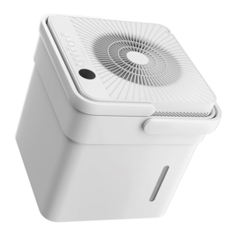
The diagram above is just for reference. Please take the appearance of the actual product as the standard.
Advertisement
Table of Contents

Related Manuals for Midea MDDM-20DEN7-QA3


Summary of Contents for Midea MDDM-20DEN7-QA3
- Page 1 DEHUMIDIFIER USER MANUAL MODEL NUMBER MDDM-20DEN7-QA3 NEW MIDEA Warning notices: Before using this product, please read this manual carefully and keep it for future reference. The design and specifications are subject to change without prior notice for product improvement. Consult with your dealer or manufacturer for details.
-
Page 3: Table Of Contents
THANK YOU LETTER Thank you for choosing Midea! Before using your new Midea product, please read this manual thoroughly to ensure that you know how to operate the features and functions that your new appliance o ers in a safe way. -
Page 4: Safety Precautions
SAFETY PRECAUTIONS To prevent injury to the user or personal and property damage, these instructions must be followed. Incorrect operation due to ignoring of instructions may cause harm or damage. The level of risk is shown by the following indications. Explanation of Symbols WARNING This symbol indicates a hazardous situation which, if not avoided,... - Page 5 CAUTION • This appliance can be used by children aged from 8 years and above and person with reduced physical, sensory or mental capabilities or lack of experience and knowledge if they have been given supervision or instruction concerning use of the appliance in a safe way and understand the hazards involved.
- Page 6 Note about Fluorinated Gasses(Not applicable to the unit using R290 Refrigerant) 1. Fluorinated greenhouse gases are contained in hermetically sealed equipment. For specific information on the type, the amount and the CO2 equivalent in tonnes of the fluorinated greenhouse gas(on some models), please refer to the relevant label on the unit itself.
- Page 7 SAFETY PRECAUTIONS CAUTION: Risk of fire/ flammable materials Explanation of symbols displayed on the unit(For the unit adopts R32/R290 Refrigerant only): This symbol shows that this appliance used a flammable refrigerant. If the refrigerant is leaked and WARNING exposed to an external ignition source, there is a risk of fire.
- Page 8 exposing any pipe work that contains or 9)Checks to electrical devices has contained flammable refrigerant Repair and maintenance to electrical shall use any sources of ignition in such components shall include initial safety a manner that it may lead to the risk of checks and component inspection fire or explosion.
- Page 9 8.Repair to intrinsically safe components pipe-work. If a leak is suspected, all Do not apply any permanent inductive naked flames shall be removed/ or capacitance loads to the circuit with- extinguished. If a leakage of refrigerant out ensuring that this will not exceed is found which requires brazing, all of the permissible voltage and current the refrigerant shall be recovered from...
- Page 10 Ensure that the refrigeration system is correctly and the process completed, make sure that the cylinders and the earthed prior to charging the system with refrigerant. Label the system when equipment are removed from site charging is complete (if not already). promptly and all isolation valves on the Extreme care shall be taken not to equipment are closed o .
- Page 11 Consult manufacturer if in doubt. The recovered refrigerant shall be returned to the refrigerant supplier in the correct recovery cylinder, and the relevant Waste Transfer Note arranged. Do not mix refrigerants in recovery units and especially not in cylinders. If compressors or compressor oils are to be removed, ensure that they have been evacuated to an acceptable level to make certain that flammable refrigerant does not remain within the lubricant.
-
Page 12: Product Overview
PRODUCT OVERVIEW NOTE ON ILLUSTRATIONS: All the illustrations in the manual are for explanation purpose only. Your machine may be slightly di erent. The actual shape shall prevail. The unit can be controlled by the unit control panel alone. Product overview Quick glance Power cord light (Some models) -
Page 13: Set Up Instructions 1
SET UP INSTRUCTIONS Step 1: Separate dehumidifier & bucket from the nested shipping/storage position. Remove all packaging materials from the unit. Nested Shipping & Storage Position Fig. 3a Fig. 3b Step 2: Rotate dehumidifier 90° and align the arrows on the two labels (one on the bucket and one on the dehumidifier) and carefully sit the dehumidifier down onto the bucket. -
Page 14: Installation Instructions 1
INSTALLATION INSTRUCTIONS Positioning the Unit More than 40cm(16”) More than 20cm(8”) More than More than 20cm(8”) 20cm(8”) More than 40cm(16”) Front View Top View Fig. 5 The dehumidifier should be placed in the area where dehumidification is desired most. Adjacent rooms in which dehumidification is also desired should allow adequate airflow in and out of the space containing the dehumidifier. -
Page 15: Operation Instructions 1
OPERATION INSTRUCTIONS Control Panel Indicator Function Indicator Function Indicator Function Wireless light Filter clean light UV light Fresh light Pump light Bucketless Mode NOTICE: The appearance of the control panel on your unit may vary slightly. Functions will be similar. When you push the button to change operation modes, the unit will make a beep sound to indicate that it is changing modes. - Page 16 Description Humidity Set Control buttons In Setting dehumidifying mode, The humidity level can be set within a range of 35%RH(Relative Humidity) to 85%RH(Relative Humidity) UP and DOWN Button in 5% increments. Press and hold the button the humidity drop continuously.Press and hold the button the humidity rise continuously.
- Page 17 Description Press and hold on the POWER button for 3 seconds to initiate the Wireless connection mode. The LED DISPLAY shows’AP’ to indicate you can set Wireless connection. If connection (router) is successful Wireless button within 8 minutes, the unit will exit Wireless connection mode (On some models) automatically and the Wireless indicator illuminates and the unit enters the previous function.
- Page 18 Setting dehumidifying mode Dryer mode(On some models) At setting dehumidifying mode, the unit can be The unit can make the MAX dehumidification adjusted in a range 35%~85%, and the humidity function when it is under Dryer mode. The fan speed setting can be adjusted (increase/decreasing) in 5%.
-
Page 19: Bucketless Mode
BUCKETLESS MODE NOTE It may cause an unexpected exit from the bucketless mode when the tank float touches the micro switch (at the bottom of the unit). So please check whether the bottom of the unit is clear under the bucketless mode. The dehumidifier can be used without bucket when the unit is under Bucketless mode. -
Page 20: Removing Collected Water
REMOVING COLLECTED WATER There are two ways to remove collected water. 1. Lift the dehumidifier by the handle, separate the it from the bucket and 1. Use the bucket put it aside. · When the unit is o ,if the bucket is full, the unit will beep 8 times(on some models) and the LED DISPLAY shows “P2”. - Page 21 CARE AND MAINTENANCE Care and cleaning of the dehumidifier. Turn the dehumidifier o and remove the plug from the wall outlet before cleaning. Clean the Grille and Case · Use water and a mild detergent. Do not use bleach or abrasives. ·...
-
Page 22: Nesting And Storing Instructions
NESTING AND STORING INSTRUCTIONS Step 1: Power o and unplug the unit. Then lift the dehumidifier o the bucket. Step 2: Empty all water from bucket. WARNING Make sure the bucket is empty before nesting the dehumidifier to avoid risk of Make sure electrical shock. -
Page 23: Specifications
SPECIFICATIONS Product Model MDDM-20DEN7-QA3 NEW MIDEA 220-240V~ 50Hz, 1Ph Power source 20 L/DAY Capacity (DB=30 RH=80%) 2.3A Rated current 430W Rated power input Resistance class IPX0... -
Page 24: Troubleshooting
TROUBLESHOOTING Before calling for service, review the chart below first yourself. Problem What to check · Make sure the dehumidifier s plug is pushed completely into the outlet. Unit does not · Check the house fuse/circuit breaker box. start · Dehumidifier has reached its preset level or bucket is full. ·... -
Page 25: Trademarks, Copyrights And Legal Statement
Midea Group and/or its a liates (“Midea”), to which Midea owns trade- marks, copyrights and other intellectual property rights, and all goodwill derived from using any part of an Midea trademark. -
Page 26: Data Protection Notice
European Economic Area. Further information are provided on request. You can contact our Data Protection O cer via MideaDPO@midea.com. To exercise your rights such as right to object your personal date being processed for direct marketing purposes, please contact us via MideaDPO@midea.com. - Page 27 WARRANTY CARD MIDEA DEHUMIDIFIER Thank you for purchasing this midea dehumidifier unit. Should your product prove to be defec�ve in material or workmanship under normal use within the 1 Year of ownership we will replace the defec�ve part(s) we deem to be faulty, or at our discre�on replace the en�re product.
- Page 28 CD001UI-DM 20230314...
Need help?
Do you have a question about the MDDM-20DEN7-QA3 and is the answer not in the manual?
Questions and answers