Table of Contents
Advertisement
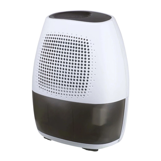
SERVICE MANUAL
MIDEA DEHUMIDIFIER
Factory Model
EU-CF0.3BD/N3-T1(A3)
EU-CFK0.3BD/N3-T1(A3)
EU-CFZ0.3BD/N3-T1(A3)
EU-CF0.4BD/N3-T1(A3)
EU-CFK0.4BD/N3-T1(A3)
EU-CFZ0.4BD/N3-T1(A3)
EU-CFK0.6BD/N3-T1(A3)
EU-CFZ0.6BD/N3-T1(A3)
EU-CF0.6BD/N3-T1(A3)
EU-CF0.8BD/N3-T1(A3)
EU-CFK0.8BD/N3-T1(A3)
EU-CFZ0.8BD/N3-T1(A3)
EU-CFZ0.4BD/N3-T2(A3)
T1 SERIES
MDT1-08DMN3-QA3
MDT1-08DKN3-QA3
MDT1-08DEN3-QA3
MDT1-10DMN3-QA3
MDT1-10DKN3-QA3
MDT1-10DEN3-QA3
MDT1-16DKN3-QA3
MDT1-16DEN3-QA3
MDT1-16DMN3-QA3
MDT1-20DMN3-QA3
MDT1-20DKN3-QA3
MDT1-20DEN3-QA3
T2 SERIES
MDT2-10DEN3
YDT1/T2101221 (0)
Sale Model
Advertisement
Table of Contents

Subscribe to Our Youtube Channel
Related Manuals for Midea MDT1-08DMN3-QA3


Summary of Contents for Midea MDT1-08DMN3-QA3
- Page 1 YDT1/T2101221 (0) SERVICE MANUAL MIDEA DEHUMIDIFIER T1 SERIES Factory Model Sale Model EU-CF0.3BD/N3-T1(A3) MDT1-08DMN3-QA3 EU-CFK0.3BD/N3-T1(A3) MDT1-08DKN3-QA3 EU-CFZ0.3BD/N3-T1(A3) MDT1-08DEN3-QA3 EU-CF0.4BD/N3-T1(A3) MDT1-10DMN3-QA3 EU-CFK0.4BD/N3-T1(A3) MDT1-10DKN3-QA3 EU-CFZ0.4BD/N3-T1(A3) MDT1-10DEN3-QA3 EU-CFK0.6BD/N3-T1(A3) MDT1-16DKN3-QA3 EU-CFZ0.6BD/N3-T1(A3) MDT1-16DEN3-QA3 EU-CF0.6BD/N3-T1(A3) MDT1-16DMN3-QA3 EU-CF0.8BD/N3-T1(A3) MDT1-20DMN3-QA3 EU-CFK0.8BD/N3-T1(A3) MDT1-20DKN3-QA3 EU-CFZ0.8BD/N3-T1(A3) MDT1-20DEN3-QA3 T2 SERIES EU-CFZ0.4BD/N3-T2(A3) MDT2-10DEN3...
-
Page 2: Table Of Contents
CONTENTS 1. Precaution ..............................1 1.1 Safety Precaution.......................... 1 1.2 Warning ................Ошибка! Закладка не определена. 2. Display................................5 3. Dimension ..............................6 4. Refrigerant Cycle Diagram ......................... 6 5. Wiring Diagram ............................7 6. Features ................................ 9 7. Electronic function ............................9 7.1 Terms and definitions ........................ -
Page 3: Precaution
1. Precaution 1.1 Safety Precaution To prevent injury to the user or other people and property damage, the following instructions must be followed. Incorrect operation due to ignoring instruction will cause harm or damage. Before service unit, be sure to read this service manual at first. 1.2 Warning ... - Page 4 Be sure the installation area does not deteriorate with age. If the base collapses, the air conditioner could fall with it, causing property damage, product failure, and personal injury. Do not let the air conditioner run for a long time when the humidity is very high and a door or a window is left open.
- Page 5 When the product is soaked (flooded or submerged), contact an Authorized service center. There is risk of fire or electric shock. Be caution that water could not enter the product. There is risk of fire, electric shock, or product damage. ...
- Page 6 consumer air conditioner, not a precision refrigerant system There is risk of damage or loss of property. Do not block the inlet or outlet of air flow. It may cause product failure. Use a soft cloth to clean. Do not use harsh detergents, solvents, etc. There is risk of fire, electric shock, or damage to the plastic parts of the product.
-
Page 7: Warning
2. Display EU-CF0.3BD/N3-T1(A3)(MDT1-08DMN3-QA3) EU-CF0.4BD/N3-T1(A3)(MDT1-10DMN3-QA3) EU-CF0.8BD/N3-T1(A3)(MDT1-20DMN3-QA3) EU-CFZ0.3BD/N3-T1(A3)(MDT1-08DEN3-QA3) EU-CFZ0.4BD/N3-T1(A3)(MDT1-10DEN3-QA3) EU-CFZ0.6BD/N3-T1(A3)(MDT1-16DEN3-QA3) EU-CFZ0.8BD/N3-T1(A3)(MDT1-20DEN3-QA3) EU-CFZ0.4BD/N3-T2(A3) (MDT2-10DEN3) -
Page 8: Dimension
Description: ① Power on indicator light(green) ② Bucket full indicator light(red) ③ Power Pad ④ Continuous operation on indicator light(green) ⑤ Display ⑥ Continue pad ⑦ Humidity set control pads 3. Dimension T1 Series T2 Series Dimension W(mm) H(mm) D(mm) Mode T1: 8L,10L... -
Page 9: Wiring Diagram
5. Wiring Diagram (1)EU-CF0.3BD/N3-T1 (A3) (MDT1-08DMN3-QA3) EU-CF0.4BD/N3-T1 (A3) (MDT1-10DMN3-QA3) EU-CF0.6BD/N3-T1 (A3) (MDT1-16DMN3-QA3) EU-CF0.8BD/N3-T1 (A3) (MDT1-20DMN3-QA3) (2)EU-CFK0.3BD/N3-T1 (A3) (MDT1-08DKN3-QA3) EU-CFK0.4BD/N3-T1 (A3) (MDT1-10DKN3-QA3) EU-CFK0.6BD/N3-T1 (A3) (MDT1-16DKN3-QA3) EU-CFK0.8BD/N3-T1 (A3) (MDT1-20DKN3-QA3) - Page 10 (3) EU-CFZ0.3BD/N3-T1 (A3) (MDT1-08DEN3-QA3) EU-CFZ0.4BD/N3-T1 (A3) (MDT1-10DEN3-QA3) EU-CFZ0.6BD/N3-T1 (A3) (MDT1-16DEN3-QA3) EU-CFZ0.8BD/N3-T1 (A3) (MDT1-20DEN3-QA3) EU-CFZ0.4BD/N3-T2 (A3) (MDT2-10DEN3)
-
Page 11: Features
6. Features ※LED display ※Auto Shut off ※Continuous dehumidification mode ※1.5L or 2.7L water bucket and water full protection ※Auto defrost, Anti-freezing control ※Turbo key function and normal key function(Optional) ※Self-diagnosis and auto-protection function. ※Wait 3 minutes before resuming operation ※Auto-restart, When the power supply is interrupted and then restore, the unit automatically restore the previous function setting. -
Page 12: Protection Function
7.4 Protection function (1).Time delay safety control (3 minutes). When the compressor is stopped in operation, it needs 3 minutes delay to restart. When the setting humidity is reached in operation, the compressor will stop, and it will not start again within 3 minutes. -
Page 13: Set Humidity Operation
LCD or LED display Stand for TH sensor malfunction TC sensor malfunction Unit is defrosting Water full protection (5).Malfunction display When the malfunction happened at the same time, the priority is P1>T2>T1 7.5 Set humidity operation (1).In this operation, the range of work is 35%RH-85%RH. (2).The fan keeps the same speed as last mode. - Page 14 Remove compressor terminal box cover and disconnect wires from terminals. Using an ohmmeter, check continuity across the following: Terminal "C" and "S" - no continuity - Open winding - replace compressor. Terminal "C" and "R" - no continuity - Open winding - replace compressor. Terminal "R"...
- Page 15 C. Low temperature difference across coil. The compressor valves are faulty - replace the compressor 8.1.4 Terminal overload (external) Some compressors are equipped with an external overload which is located in the compressor terminal box adjacent to the compressor body .The overload is wired in series with the common motor terminal.
-
Page 16: Sealed Refrigeration System Repairs
8.2 Sealed refrigeration system repairs 8.2.1 Equipment require 1. Voltmeter 2. Ammeter 3. Ohmmeter 4. E.P.A. Approved Refrigerant Recovery System. 5. Vacuum Pump (capable of 200 microns or less vacuum.) 6. Acetylene Welder 7. Electronic Halogen Leak Detector (G.E. Type H-6 or equivalent.) 8. - Page 17 4. Drift dry nitrogen through the system and unsolder the more distant connection first. (Filter drier, high side process tube, etc.) 5. Replace inoperative component, and always install a new filter drier. Drift dry nitrogen through the system when making these connections. 6.
-
Page 18: Fan Motor
1. Because of the spinning motion of the rotary, the mounts are critical. If vibration is present, check the mounts carefully. 2. The electrical terminals on the rotary are in a different order than the reciprocating compressors. The terminal markings are on the cover gasket. Use your wiring diagram to insure correct connections. -
Page 19: Capacitor
8.4 Capacitor A run capacitor is wired across the auxiliary and main winding of a single phase permanent split capacitor motor such as the compressor. A single capacitor can be used for each motor or a dual rated capacitor can be used for both. The capacitor's primary function is to reduce the line current while greatly improving the torque characteristics of a motor. -
Page 20: Characteristic Of Temperature Sensor
9 Characteristic of temperature sensor Resistance Resistance Resistance Temp.℃ Temp.℃ Temp.℃ KΩ KΩ KΩ 62.2756 14.6181 4.3874 58.7079 13.918 4.2126 56.3694 13.2631 4.0459 52.2438 12.6431 3.8867 49.3161 12.0561 3.7348 46.5725 11.5 3.5896 10.9731 3.451 41.5878 10.4736 3.3185 39.8239 3.1918 37.1988 9.5507 3.0707... - Page 21 PROBLEM POSSIBLE CAUSE REMEDY Check the power supplier if the power supplier is supplied to the Power failure unit. Check the power cord and correct if damaged. Transformer (Discharge Check resistance between the two input/output lines on transformer. No power display on transformer before Replace the transformer if either of the input/output is open or the panel or any one of the...
- Page 22 PROBLEM POSSIBLE CAUSE REMEDY Voltage Check voltage. Call Supply Authority if not within limits. Check the wire connections, if loose, repair or replace the terminal. Wiring If wires are off, refer to wiring diagram for identification, and replace. Check wire locations. If not per wiring diagram, correct. Main PCB failure Check voltage of main PCB.
-
Page 23: Exploding View
11. Exploding view (1). EU-CF0.3BD/N3-T1(A3)(MDT1-08DMN3-QA3) EU-CFZ0.3BD/N3-T1(A3)(MDT1-08DEN3-QA3) EU-CF0.4BD/N3-T1(A3)(MDT1-10DMN3-QA3) EU-CFZ0.4BD/N3-T1(A3)(MDT1-10DEN3-QA3) Part list: Part Name Qty No. Part Name Front panel assembly main control board assembly Front panel Rear panel Filter guide I Drain stopper Filter Handle Filter guide II Water tank assembly... - Page 24 (2). EU-CFK0.3BD/N3-T1(A3)(MDT1-08DKN3-QA3) EU-CFK0.4BD/N3-T1(A3)(MDT1-10DKN3-QA3) Part list: Part Name Part Name Front panel assembly main control board assembly Front panel Rear panel Filter guide I Drain stopper Filter Handle Filter guide II Water tank assembly Display box assembly 10.1 water tank Control panel 10.2 cover for water tank Display board assembly...
- Page 25 (3). EU-CFK0.6BD/N3-T1(A3)(MDT1-16DKN3-QA3) EU-CFK0.8BD/N3-T1(A3)(MDT1-20DKN3-QA3) Part list: Part Name Part Name water tank assembly Chassis assembly water tank assembly Evaporator Dobber Condenser Cover for water tank Water collector assembly Front panel assembly Micro Switch Front panel Water drain pan Filter guide I Compressor Filter Display box assembly...
- Page 26 (4). EU-CFZ0.6BD/N3-T1(A3)(MDT1-16DEN3-QA3) EU-CFZ0.8BD/N3-T1(A3)(MDT1-20DEN3-QA3) Part list: Part Name Part Name water tank assembly E-part box cover water tank assembly Chassis assembly Dobber Evaporator Cover for water tank Condenser Front panel assembly Water collector assembly Front panel Micro Switch Filter guide I Water drain pan Filter Compressor...
- Page 27 (5). EU-CF0.6BD/N3-T1(A3)(MDT1-16DMN3-QA3) EU-CF0.8BD/N3-T1(A3)(MDT1-20DMN3-QA3) Part list: Part Name Part Name water tank assembly Chassis assembly water tank assembly Evaporator Dobber Condenser Cover for water tank Water collector Front panel assembly Micro Switch Front panel Water drain pan Filter guide I Compressor Filter Display box assembly Filter guide II...
- Page 28 (6). EU-CFZ0.4BD/N3-T2(A3)(MDT2-10DEN3) Part list: Part Name Part Name water tank assembly Chassis assembly water tank assembly Evaporator Dobber Condenser Cover for water tank Water collector Front panel assembly Micro Switch Front panel Water drain pan Filter guide I Compressor Filter Display box assembly Filter guide II 11.1...
Need help?
Do you have a question about the MDT1-08DMN3-QA3 and is the answer not in the manual?
Questions and answers