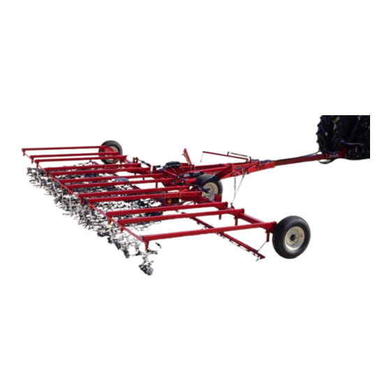
McFarlane HD-100 Series Operator's Manual And Set-Up Instructions
Chain harrow
Hide thumbs
Also See for HD-100 Series:
- Operator's manual and set-up instructions (45 pages) ,
- Operator's manual and set-up instructions (31 pages) ,
- Operator's manual and set-up instructions (31 pages)
Table of Contents
Advertisement
Quick Links
MANUFACTURERS OF QUALITY AGRICULTURAL EQUIPMENT SINCE 1936
OPERATOR'S MANUAL
AND
SET-UP INSTRUCTIONS
FOR THE
HD-100 Series
Chain Harrow
118 Through 130 Models
VERSION: 2-11
Starting at Serial Number 15243
TO THE OWNER AND OPERATORS
Before assembling or operating this unit, READ THIS MANUAL THOROUGHLY. To obtain
the best performance of the unit, familiarize yourself with each component and adjustment.
Store this manual where it can be readily available for future reference. In the event that the
harrow or any part of the unit should be sold, be sure that the new owner receives a copy of
this manual for their reference.
1330 DALLAS STREET, P.O. BOX 100
SAUK CITY, WISCONSIN 53583
PHONE: (608) 643-3321
TOLL FREE: (800) 627-8569 FAX: (608) 643-3976
Advertisement
Table of Contents

Subscribe to Our Youtube Channel
Related Manuals for McFarlane HD-100 Series


Summary of Contents for McFarlane HD-100 Series
- Page 1 MANUFACTURERS OF QUALITY AGRICULTURAL EQUIPMENT SINCE 1936 OPERATOR’S MANUAL SET-UP INSTRUCTIONS FOR THE HD-100 Series Chain Harrow 118 Through 130 Models VERSION: 2-11 Starting at Serial Number 15243 TO THE OWNER AND OPERATORS Before assembling or operating this unit, READ THIS MANUAL THOROUGHLY. To obtain the best performance of the unit, familiarize yourself with each component and adjustment.
- Page 2 TABLE OF CONTENTS...
-
Page 3: Limited Warranty
INTRODUCTION LIMITED WARRANTY... - Page 4 SAFETY ATTENTION! BECOME ALERT! YOUR SAFETY IS INVOLVED! SIGNAL WORDS: DANGER: WARNING: CAUTION:...
-
Page 5: Contact Information
CONTACT INFORMATION... -
Page 6: Safety First
SAFETY FIRST! Equipment Safety Guidelines Do not allow persons to operate or assemble this unit until they have read this manual and have developed a thorough understanding of the safety precautions and of how it works. DO NOT TRY IT Lighting and Marking Safety Sign Care... - Page 7 Tire Safety Remember Your best assurance against accidents is a careful and responsible operator. If there is any portion of this manual or function you do not understand, contact your local authorized dealer or the manufacturer. Before Operation:...
- Page 8 During Operation: particularly children! NO PASSENGERS ALLOWED remove the ignition key.
- Page 9 Following Operation: remove the ignition keys. Highway and Transport Operations: NEVER USE INDEPENDENT BRAKING WITH MACHINE IN TOW AS LOSS OF CONTROL AND/OR UPSET OF UNIT MAY RESULT.
- Page 10 Performing Maintenance: remove the ignition keys. Always injured by escaping hydraulic fluid, see a doctor at once. Gangrene can result. Without immediate medical treatment, serious infection and reactions can occur.
-
Page 11: Maintenance And Service Schedule
MAINTENANCE AND SERVICE SCHEDULE OPERATING SUGGESTIONS... -
Page 12: Assembly Suggestions
ASSEMBLY SUGGESTIONS... - Page 13 STEP - BY - STEP ASSEMBLY INSTRUCTIONS Main Frame Assembly Figure 1...
- Page 14 CLEVIS HITCH PINTLE HITCH TOP PLATE BASE HITCH CUSHION V-PLATE CLEVIS 3/4" x 5" BOLT 3/4" x 2 1/2" BOLT AND LOCK NUT BASE HITCH Figure 2 Figure 3 Attach the Center Bar Figure 4...
- Page 15 Attach and Assemble the Wing Frame 1/2 X 3 1/2 BOLT & LOCK NUT 1/2 X 3 BOLT & LOCK NUT 1 1/4 HINGE PIN Figure 5 Install the Hydraulics System...
- Page 16 Attach the Lift Arms Figure 6...
- Page 17 Attach the Pull Tubes 1/2" x 1 1/2" BOLT FLAT WASHER LOCK WASHER HEX NUT FRONT PULL TUBE Figure 7 Attach the Front of the Harrow Sections PULL ROD FRONT MAIN TUBE Figure 8...
- Page 18 Attach the Lift Chains LARGE 1 1/2" RING Figure 9 . Be sure the unit is attached to a tractor of adequate size before actuating the hydraulics! Attach the Wing Cables...
- Page 19 Figure 11 Attach the Wing Cable Lift Assembly...
- Page 20 Figure 12 Attach the Wing Rests...
- Page 21 Figure 13 Final Adjustments...
-
Page 22: Troubleshooting
TROUBLESHOOTING PROBLEM POSSIBLE CAUSE SOLUTION... - Page 23 BOLT TORQUE SPECIFICTIONS Coarse Thread Series Fine Thread Series Nut Size Nut Size Tightening Tightening Threads Torque Threads Torque per Inch (lb.ft.) per Inch (lb.ft.) Grade C Nuts Grade C Nuts Max. Min. Max. Min. 1/4 - 20 14.7 1/4 - 28 14.7 5/16 - 18 22.3 15.2...
- Page 24 HD-118 through HD-130 HARROW CART PARTS DIAGRAM...
- Page 25 HD-116 through HD-130 HARROW CART PARTS LIST McFarlane Manufacturing reserves the right to change specifications of design at any time without obligation to modify previous products.
-
Page 26: Parts Diagram & List
PARTS DIAGRAM & LIST McFarlane Manufacturing reserves the right to change specifications of design at any time without obligation to modify previous products. - Page 27 HD-118 through 130 HARROW CART HYDRAULICS DIAGRAM & LISTING McFarlane Manufacturing reserves the right to change specifications of design at any time without obligation to modify previous products.
- Page 28 HD-120-U LAYOUT DIAGRAM...
- Page 29 HD-124-U LAYOUT DIAGRAM...
- Page 30 HD-130-U LAYOUT DIAGRAM...
-
Page 31: Warranty Registration Form
WARRANTY REGISTRATION FORM This form must be filled out by the dealer and owner and sent to: McFarlane Mfg. Co., Inc., 1330 Dallas Street, P.O. Box 100, Sauk City, WI 53583. WARRANTY REGISTRATION FORM & INSPECTION REPORT WARRANTY REGISTRATION This form must be filled out by the dealer and signed by both the dealer and customer at the time of delivery.
Need help?
Do you have a question about the HD-100 Series and is the answer not in the manual?
Questions and answers