McFarlane HD-130 Operator's Manual And Set-Up Instructions
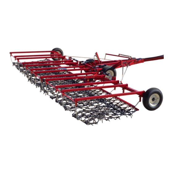
Chain harrow
Hide thumbs
Also See for HD-130:
- Operator's manual and set-up instructions (31 pages) ,
- Operator's manual and set-up instructions (31 pages)
Table of Contents
Advertisement
Quick Links
MANUFACTURERS OF QUALITY AGRICULTURAL EQUIPMENT SINCE 1936
OPERATOR'S MANUAL
AND
SET-UP INSTRUCTIONS
FOR THE
HD-100 Series
Chain Harrow
118 Through 130 Models
VERSION: 2-11
Serial Number 15243 through 17875
TO THE OWNER AND OPERATORS
Before assembling or operating this unit, READ THIS MANUAL THOROUGHLY. To obtain
the best performance of the unit, familiarize yourself with each component and adjustment.
Store this manual where it can be readily available for future reference. In the event that the
harrow or any part of the unit should be sold, be sure that the new owner receives a copy of
this manual for their reference.
1330 DALLAS STREET, P.O. BOX 100
SAUK CITY, WISCONSIN 53583
PHONE: (608) 643-3321
TOLL FREE: (800) 627-8569 FAX: (608) 643-3976
Advertisement
Table of Contents

Subscribe to Our Youtube Channel
Related Manuals for McFarlane HD-130


Summary of Contents for McFarlane HD-130
- Page 1 MANUFACTURERS OF QUALITY AGRICULTURAL EQUIPMENT SINCE 1936 OPERATOR’S MANUAL SET-UP INSTRUCTIONS FOR THE HD-100 Series Chain Harrow 118 Through 130 Models VERSION: 2-11 Serial Number 15243 through 17875 TO THE OWNER AND OPERATORS Before assembling or operating this unit, READ THIS MANUAL THOROUGHLY. To obtain the best performance of the unit, familiarize yourself with each component and adjustment.
-
Page 2: Table Of Contents
TABLE OF CONTENTS INTRODUCTION .......................3 LIMITED WARRANTY .....................3 SAFETY ..........................4 CONTACT INFORMATION ....................5 LIGHTING AND MARKING .....................6 SAFETY SIGN CARE ......................7 TIRE SAFETY ........................7 BEFORE OPERATION ....................7 - 8 DURING OPERATION ....................8 - 9 FOLLOWING OPERATION ....................9 HIGHWAY AND TRANSPORT OPERATIONS ............9 - 10 PERFORMING MAINTENANCE ...................10 MAINTENANCE AND SERVICE SCHEDULE .............11 OPERATING SUGGESTIONS ..................11... -
Page 3: Introduction
HD-100 Series If within one year from the date of purchase, this transport cart and/or its accompanying harrow sections fail due to defect in material or workmanship, McFarlane Mfg. Co., Inc. will repair it, free of charge. Warranty service is available by simply contacting the nearest McFarlane dealership throughout the United States or Canada. -
Page 4: Safety
SAFETY TAKE NOTE! THIS SAFETY ALERT SYMBOL FOUND THROUGHOUT THIS MANUAL IS USED TO CALL ATTENTION TO INSTRUCTIONS INVOLVING YOUR PERSONAL SAFETY AND THE SAFETY OF OTHERS. FAILURE TO FOLLOW THESE INSTRUCTIONS CAN RESULT IN INJURY OR DEATH. THIS SYMBOL MEANS ... -
Page 5: Contact Information
CONTACT INFORMATION If you have questions not answered in this manual, require additional copies, or the manual is damaged, please contact your local dealer or: McFarlane Mfg. Co., Inc. 1330 Dallas Street P.O. Box 100 Sauk City, WI 53583 PHONE:... -
Page 6: Lighting And Marking
SAFETY FIRST! Equipment Safety Guidelines Safety of the operator is one of the main concerns in designing and developing a new piece of equipment. Designers and manufacturers build in as many safety features as possible. However, every year many accidents occur which could have been avoided by a few seconds of thought and a more careful approach to handling equipment. -
Page 7: Tire Safety
How to Install Safety Signs: Be sure that the installation area is clean and dry. Decide on the exact position before you remove the backing paper. Tire Safety Failure to follow proper procedures when mounting a tire on a wheel or rim can produce an explosion which may result in serious injury or death. -
Page 8: During Operation
Securely attach to towing unit. Use a high strength, appropriately sized hitch pin with a mechanical retainer and attach safety chain. Do not allow anyone to stand between the tongue or hitch and the towing vehicle when backing up to the equipment. During Operation: ... -
Page 9: Following Operation
Following Operation: When disconnecting, stop the tractor or towing vehicle, set the brakes, secure the wings in the wing rests, relieve hydraulic fluid pressure, shut off the engine and remove the ignition keys. Make sure all jack and support stands are in place before removing hitch pins. ... -
Page 10: Performing Maintenance
Be observant of bridge loading ratings. Do not cross bridges rated lower than the gross weight at which you are operating. Watch for obstructions overhead and to the side while transporting. Always operate equipment in a position to provide maximum visibility at all times. Make allowances for increased length and weight of the equipment when making turns, stopping, etc. -
Page 11: Maintenance And Service Schedule
OPERATING SUGGESTIONS There are some important points to remember in order to obtain the best possible results from your McFarlane harrow. To maximize the harrow’s performance, it should be towed at speeds ranging from six to nine (6 - 9) mph. This keeps the field debris moving through the harrow sections and avoids clogging. -
Page 12: Assembly Suggestions
ASSEMBLY SUGGESTIONS You will find the machine is easier to assemble if the set-up instructions are followed in the order given in the manual. Before beginning, sort the various bolt bags, hardware bags and hydraulic bags according to what part of the unit that is being setup. -
Page 13: Assembly Instructions
STEP - BY - STEP ASSEMBLY INSTRUCTIONS Main Frame Assembly 1. Bolt the Hitch Tube to the Main Frame using 1 x 8 bolts and lock nuts. Note that there are different positions for the Hitch Tube. 2. Insert the Hub and Spindle into the Main Frame and secure using ½ x 3 ½ bolts and lock nuts. Install the 11L tires. - Page 14 CLEVIS HITCH PINTLE HITCH TOP PLATE BASE HITCH CUSHION V-PLATE CLEVIS 3/4" x 5" BOLT 3/4" x 2 1/2" BOLT AND LOCK NUT BASE HITCH Figure 2 Figure 3 Attach the Center Bar 1. Attach the Center Bar to the Main Frame using 1 ¼ x 5 ½ bolts and nylon jam nuts. Install the 4 x 8 cylinders as shown.
- Page 15 Attach and Assemble the Wing Frame 1. Attach the Wing Frame to the Center Bar using the 1 ¼ Hinge Pins and ½ x 3 bolts and lock nuts. 2. Insert a Hub and Spindle into the tube on the end of the Wing and secure using a ½ x 3 ½ bolt and lock nut.
- Page 16 8. Attach the 252” to the rod end of the 4 x 8 cylinder on the right hand side of the unit. Attach the 240” hose to the base end and then run both hoses to the hitch. 9. Secure all hoses to the frame to prevent damage between moving parts or from contacting the ground.
- Page 17 Attach the Pull Tubes 1. Refer to the layout diagram in appendix C and place the pull tubes behind the pull points. Bolt them to the pull chains using a 1/2” x 1 1/2” bolt, lock washer and hex nut for each pull chain. 1/2"...
- Page 18 Attach the Lift Chains 1. Refer to figure 18 below. Wrap the 16-link lift chains around the second to last cross piece below and in front of the end of the lift tube and feed the chain back through the large 1/2”...
- Page 19 Figure 11 Attach the Wing Cable Lift Assembly 1. Bolt the Cable Lift Bracket to the Main Frame approximately 24” from the front of the frame side tube. Use two ½ x 3 x 7 U-bolts and lock nuts. Do not tighten yet. 2.
- Page 20 Figure 12 Attach the Wing Rests Place the Wing Rests approximately 18” ahead of the cylinder post on the Main Frame. Bolt firmly in place using the 5/8 x 6 x 4 U-bolts and lock nuts. Do not tighten yet.
- Page 21 Figure 13 Final Adjustments 1. Unfold the unit into the field position and fully extend all cylinders. 2. Slowly fold the unit into the transport position. Be sure the Wing Frames engage the ramp on the Wing Rest and fully sit on it. It may be necessary to adjust the Wing Rest back/forward. It may also be necessary to adjust the stroke control collar on the 4x8 main lift cylinders.
- Page 22 This completes the assembly of your harrow and transport cart. Before using the unit, double check that all components have been assembled properly. If there are any questions regarding any of the assembly steps, contact your local dealer for an explanation. Do not operate this or any equipment unless you are sure that all components operate as they were designed to operate.
- Page 23 BOLT TORQUE SPECIFICTIONS Coarse Thread Series Fine Thread Series Nut Size Nut Size Tightening Tightening Threads Torque Threads Torque per Inch (lb.ft.) per Inch (lb.ft.) Grade C Nuts Grade C Nuts Max. Min. Max. Min. 1/4 - 20 14.7 1/4 - 28 14.7 5/16 - 18 22.3 15.2...
- Page 24 HD-118 through HD-130 HARROW CART PARTS DIAGRAM APPENDIX B...
- Page 25 Please specify model number when ordering these parts. Bolts, washers, nuts, and cotter pins are not shown. Refer to the step-by-step assembly instructions for details. McFarlane Manufacturing reserves the right to change specifications of design at any time without obligation to modify previous products. APPENDIX B...
- Page 26 Please specify model number when ordering these parts. Bolts, washers, nuts, and cotter pins are not shown. Refer to the step-by-step assembly instructions for details. McFarlane Manufacturing reserves the right to change specifications of design at any time without obligation to modify previous products. APPENDIX B...
- Page 27 HYO-2103 1" x 3 1/2" CLEVIS PIN Note: When ordering replacement parts, please specify cylinder make & part number. McFarlane Manufacturing reserves the right to change specifications of design at any time without obligation to modify previous products. APPENDIX B...
-
Page 28: Final Adjustments
HD-120-U LAYOUT DIAGRAM APPENDIX C... -
Page 29: Troubleshooting
HD-124-U LAYOUT DIAGRAM APPENDIX C... - Page 30 HD-130-U LAYOUT DIAGRAM APPENDIX C...
-
Page 31: Warranty Registration Form
WARRANTY REGISTRATION FORM This form must be filled out by the dealer and owner and sent to: McFarlane Mfg. Co., Inc., 1330 Dallas Street, P.O. Box 100, Sauk City, WI 53583. WARRANTY REGISTRATION FORM & INSPECTION REPORT WARRANTY REGISTRATION This form must be filled out by the dealer and signed by both the dealer and customer at the time of delivery.
Need help?
Do you have a question about the HD-130 and is the answer not in the manual?
Questions and answers