Table of Contents
Advertisement
MANUFACTURERS OF QUALITY AGRICULTURAL EQUIPMENT SINCE 1936
OPERATOR'S MANUAL
AND
PARTS LISTING
FOR THE
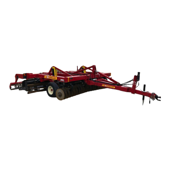
RD-4000 Series
Reel Disk
VERSION: 7-12
starting at serial number 16537
TO THE OWNER AND OPERATORS
Before assembling or operating this unit, READ THIS MANUAL THOROUGHLY. To obtain
the best performance of the unit, familiarize yourself with each component and adjustment.
Store this manual where it can be readily available for future reference. In the event that the
harrow or any part of the unit should be sold, be sure that the new owner receives a copy of
this manual for their reference.
1330 DALLAS STREET, P.O. BOX 100
SAUK CITY, WISCONSIN 53583
PHONE: (608) 643-3321
TOLL FREE: (800) 627-8569 FAX: (608) 643-3976
Advertisement
Table of Contents

Related Manuals for McFarlane RD-4000 Series


Summary of Contents for McFarlane RD-4000 Series
- Page 1 MANUFACTURERS OF QUALITY AGRICULTURAL EQUIPMENT SINCE 1936 OPERATOR’S MANUAL PARTS LISTING FOR THE RD-4000 Series Reel Disk VERSION: 7-12 starting at serial number 16537 TO THE OWNER AND OPERATORS Before assembling or operating this unit, READ THIS MANUAL THOROUGHLY. To obtain the best performance of the unit, familiarize yourself with each component and adjustment.
-
Page 2: Table Of Contents
TABLE OF CONTENTS INTRODUCTION .......................3 LIMITED WARRANTY .....................3 CONTACT INFORMATION ....................3 SAFETY .......................... 4-6 BEFORE OPERATION .......................6 DURING OPERATION ......................7 FOLLOWING OPERATION ..................7-8 HIGHWAY AND TRANSPORT OPERATIONS ..............8 OPERATING INSTRUCTIONS ................... 9-13 MAINTENANCE AND SERVICE ................13-15 TROUBLESHOOTING .....................16 BOLT TORQUE AND TIRE SPECIFICATIONS ............17 PARTS DIAGRAMS - HITCH ................... -
Page 3: Introduction
INTRODUCTION Thank you for purchasing your new McFarlane tillage tool. We know that you will get many years of dependable service from this modernly designed unit. You may have had a particular application in mind when you purchased this unit. There are actually many uses for the McFarlane harrow including incorporation of herbicides and pesticides, leveling and smoothing tilled soil, and covering of broadcast seeds. -
Page 4: Safety
SAFETY TAKE NOTE! THIS SAFETY ALERT SYMBOL FOUND THROUGHOUT THIS MANUAL IS USED TO CALL ATTENTION TO INSTRUCTIONS INVOLVING YOUR PERSONAL SAFETY AND THE SAFETY OF OTHERS. FAILURE TO FOLLOW THESE INSTRUCTIONS CAN RESULT IN INJURY OR DEATH. THIS SYMBOL MEANS ATTENTION! BECOME ALERT! YOUR SAFETY IS INVOLVED! - Page 5 SAFETY FIRST! Equipment Safety Guidelines Safety of the operator is one of the main concerns in designing and developing a new piece of equipment. Designers and manufacturers build in as many safety features as possible. However, every year many accidents occur which could have been avoided by a few seconds of thought and a more careful approach to handling equipment.
-
Page 6: Before Operation
Tire Safety Failure to follow proper procedures when mounting a tire on a wheel or rim can produce an explosion which may result in serious injury or death. Do not attempt to mount tires unless you have the proper equipment and experience to do the job. Inflating or servicing tires can be dangerous. -
Page 7: During Operation
During Operation: SAFETY CHAIN - If equipment is going to be transported on a public highway, a safety chain should be obtained and installed. Always follow state and local regulations regarding a safety chain when towing farm equipment on a public highway. Be sure to check with local law enforcement agencies for your own particular regulations. -
Page 8: Highway And Transport Operations
Do not park equipment where it will be exposed to livestock for long periods of time. Damage and livestock injury could result. Do not permit children to play on or around the stored unit. Highway and Transport Operations: Make sure all transport lock provisions are in place and jack/parking stands are in their storage position before transporting the unit. -
Page 9: Operating Instructions
OPERATING INSTRUCTIONS To maximize the unit’s performance, it should be towed at speeds ranging from six to nine (6-9) mph. This keeps the field debris moving through the harrow sections and avoids clogging. The best results will be obtained after the paint has been scoured from the soil engaging components. Transporting the unit Getting the unit ready for transport (figure 1) Lift the entire unit up and fold the wings into the wing rests. - Page 10 Figure 2 Setting disk gang depth (figure 3) Adjust the hitch turnbuckle (1) with the turnbuckle wrench (2) provided to level the unit from front to back. This ensures that the disk gang is set at the same depth as the spiral reels. Make a note of the mark on the depth gauge (3) that is located on the turnbuckle lock (4).
- Page 11 Figure 3 Setting the center disks (figure 4) Adjust the center disks inward or outward to prevent ridges or gaps from forming in the center of the unit. The angle of the center disks can also be changed by loosening the back bolt of the mounting bracket and twisting to the desired angle.
- Page 12 Adjusting the harrow section aggressiveness (figures 5 and 6) In the least aggressive direction there are three attachment points for the pull chains on the harrow section. Moving it up will cause the section to lay more flat (less aggressive) and moving it down will cause the teeth to stand up more straight (more aggressive).
- Page 13 Figure 7 * Adjust the spring tension just tight enough to prevent it from loosening and falling out when in the raised position. Set the rolling basket height by lowering the unit onto a flat surface and adjusting the basket to just touch the ground. During operation the spring should only lightly stretch, approximately 1/16”...
-
Page 14: Maintenance And Service
Where replacement parts are necessary for periodic maintenance and servicing, genuine factory replacement parts must be used to restore your equipment to original specifications. The manufacturer will not claim responsibility for damages as a result of the use of unapproved parts. If equipment has been altered in any way from original design, the manufacturer does not accept any liability for injury or warranty. - Page 15 Disk Gang & Blades It will be necessary to check and tighten the disk gang arbor bolts to prevent excessive wear. It is recommended that the gang arbor bolts be tightened to a torque between 600 and 800 ft-lb. A torque of 600 ft-lb would be equivalent to using a 4’...
-
Page 16: Troubleshooting
TROUBLESHOOTING AND ADJUSTMENT GUIDE Problem Solution Unit not running to desired Be sure unit is completely lowered to the ground. depth. Lower disk gang to no more than 3” below the depth of the spiral reel using the hitch turnbuckle. Increase disk gang angle to loosen more soil Soil not fully worked to Lower disk gang to no more than 3”... - Page 17 BOLT TORQUE SPECIFICTIONS Coarse Thread Series Fine Thread Series Nut Size Nut Size Tightening Tightening Threads Torque Threads Torque per Inch (lb.ft.) per Inch (lb.ft.) Grade C Nuts Grade C Nuts Max. Min. Max. Min. 1/4 - 20 14.7 1/4 - 28 14.7 5/16 - 18 22.3 15.2...
- Page 18 HI TCH FRAME FOR RD-4000 SERI ES Part No. Description Notes/ Revisions RD-4411 HI TCH, 4X6 (4012-4014) RD-4409 HI TCH, 4X6 (4016-4030) RD-4418 HI TCH, 6X6 (4035-4045) RT-2107 HI NGE PI N, 1-1/ 2x9-5/ 8 BHY-5635 9/ 16 - 12 X 3 1/ 2 GRADE 8 BOLT NLT-5612 9/ 16-12 TOP LOCK NUT RT-2112...
- Page 19 HI TCH FRAME (continued) BH-2510 1/ 4 X 1 HEX BOLT RD-4308 HYDRAULI C HOSE RACK NLT-1008 1” TOP LOCK NUT PPI -200 HI TCH BASE CAT I I (4012-4016) See drawbar hitch diagram PPI -300 HI TCH BASE CAT I I I (4020) for details PPI -400 HI TCH BASE CAT I V (4025-4045)
- Page 20 MAI N FRAME AXLE FOR RD-4012, 4014, 4016, 4020, 4025 AND 4030...
- Page 21 MAI N FRAME AXLE (continued) FOR RD-4012, 4014, 4016, 4020, 4025 AND 4030 Part No. Description Notes/ Revisions RD-4361 MAI N AXLE CYLI NDER ARM HYO-2103 CYLI NDER CLEVI S PI N, 1 X 3 CP-3620 3/ 16 X 2 COTTER PI N NLT-1008 1”...
- Page 22 MAI N FRAME AXLE FOR RD-4035 AND RD-4045...
- Page 23 MAI N FRAME AXLE FOR RD-4035 AND RD-4045 (continued) Part No. Description Notes/ Revisions RD-4361 MAI N AXLE CYLI NDER ARM (4035) RD-4637 MAI N AXLE CYLI NDER ARM (4045) HYO-2103 CYLI NDER CLEVI S PI N, 1 X 3 CP-3620 3/ 16 X 2 COTTER PI N NLT-1008...
- Page 24 LEVEL LI FT and CYLI NDER LOCK FOR RD-4000 SERI ES Part No. Description Notes/ Revisions BH-2510 1/ 4 – 20 X 1 GRADE 5 HEX BOLT HYS-1104 CYLI NDER LOCK HANDLE LOCK NLT-2520 1/ 4 - 20 TOP LOCK NUT HYS-1103 CYLI NDER LOCK HANDLE CP-1810...
- Page 25 HYDRAULI C DEPTH STOP FOR RD-4000 SERI ES Part No. Description Notes/ Revisions RD-4351 HYDRAULI C STOP TUBE ASSEMBLY CP-3620 3/ 16 X 2 COTTER PI N NLT-3816 3/ 8 – 16 X TOP LOCK NUT RD-4356 HYDRAULI C STOP AXLE BRACKET BH-3810 3/ 8 –...
- Page 26 WI NG REST & SMV FOR 4020 Part No. Description Notes/ Revisions BH-5015 1/ 2 – 13 X 1 1/ 2 GRADE 5 HEX BOLT RT-3415 WI NG REST BUMPER RD-4488 WI NG REST, LEFT HAND (SHOWN) RD-4489 WI NG REST, RI GHT HAND BH-6325 5/ 8 –...
- Page 27 WI NG REST & SMV FOR 4025, 4030 AND 4035 Part No. Description Notes/ Revisions BU-5867 5/ 8 - 11 X 6 X 7 1/ 2 U-BOLT LW-0063 5/ 8 LOCK WASHER NH-6311 5/ 8 – 11 HEX NUT RD-4620 WI NG REST ASSEMBLY, RI GHT (4025) RT-3434 WI NG REST ASSEMBLY, RI GHT (4030)
- Page 28 WI NG REST & SMV FOR 4045 Part No. Description Notes/ Revisions BH-5015 1/ 2 -13 X 1 1/ 2 GRADE 5 HEX BOLT RT-3415 WI NG REST BUMPER RD-4636 WI NG REST (4045) LW-0063 5/ 8 LOCK WASHER NH-6311 5/ 8 –...
- Page 29 WI NG FRAME FOR 4020, 4025, 4030 AND 4035 Part No. Description Notes/ Revisions BHY-5635 9/ 16 - 12 X 3 1/ 2 GRADE 8 BOLT NLT-5612 9/ 16-12 TOP LOCK NUT RT-2107 WI NG HI NGE PI N, 1 1/ 2 X 9 5/ 8 BHY-1033 1”...
- Page 30 WI NG FRAME, I NSI DE FOR 4045 Part No. Description Notes/ Revisions BHY-5635 9/ 16 - 12 X 3 1/ 2 GRADE 8 BOLT NLT-5612 9/ 16-12 TOP LOCK NUT RT-2107 WI NG HI NGE PI N, 1 1/ 2 X 9 5/ 8 BHY-1033 1”...
- Page 31 WI NG FRAME, OUTSI DE FOR 4045 Part No. Description Notes/ Revisions BHY-5635 9/ 16 - 12 X 3 1/ 2 GRADE 8 BOLT NLT-5612 9/ 16-12 TOP LOCK NUT SPR-2712 HI NG PI N, 1 1/ 2 X 8 1/ 4 RD-4425 WI NG FOLD ARM, LEFT NLT-1008...
- Page 32 DI SK MOUNT AND SCRAPERS FOR RD-4000 SERI ES Part No. Description Notes/ Revisions BHY-1380 1 1/ 4 – 7 X 8 GRADE 8 HEX BOLT NY-1307 1 1/ 4 - 7 NYLON LOCK NUT RD-4431 1-8 X 7 GRADE 8 HEX BOLT w/ CROSS HOLE RD-4439 DI SK MOUNT TUBE CLAMP PLATE NC-1008...
- Page 33 RD-4457 DI SK MOUNT TUBE, WI NG, RI GHT (4035) RD-4638 DI SK MOUNT TUBE, MAI N/ WI NG, LEFT (4045) RD-4639 DI SK MOUNT TUBE, MAI N/ WI NG, RI GHT (4045) RD-4429 DI SK MOUNT TUBE, WI NG, LEFT OUTSI DE (4045) RD-4430 DI SK MOUNT TUBE, WI NG, RI GHT OUTSI DE (4045) BHY-7535...
- Page 34 DI SK GANG FOR RD-4000 SERI ES Part No. Description Notes/ Revisions BH-2525 1/ 4 - 20 X 2 1/ 2 GRADE 5 HEX BOLT NC-1406 1 3/ 8 – 6 CASTLE NUT NLT-2520 1/ 4 TOP LOCK NUT FW-0138 1 3/ 8 MACHI NE WASHER RD-4843 DI SK END SPACER DOM...
- Page 35 CENTER COVERI NG DI SK FOR RD-4000 SERI ES Part No. Description Notes/ Revisions BH-6355 5/ 8 – 11 X 5 1/ 2 GRADE 5 HEX BOLT RD-4464 SPRI NG CLAMP PLATE RD-4432 SPRI NG CLAMP PLATE NLT-6311 5/ 8 - 11 TOP LOCK NUT RD-4465 CENTER DI SK SPRI NG BH-6325...
- Page 36 SPI RAL REEL FOR RD-4000 SERI ES Part No. Description Notes/ Revisions BHY-7535 3/ 4 - 10 X 3 1/ 2 GRADE 8 BOLT BH-6325 5/ 8-11 X 2 1/ 2 GRADE 5 BOLT NLT-6311 5/ 8 - 11 TOP LOCK NUT RT-2611 C-SPRI NG TOP CLAMP NLT-7510...
- Page 37 SPI RAL REEL (continued) BH-5028 1/ 2 – 13 X 2 3/ 4 GRADE 5 HEX BOLT SPR-2353 BEARI NG GUARD, 5/ 8” SPR-5105 SPI RAL REEL BEARI NG ASSEMBLY SPR-5106 SPI RAL REEL BEARI NG HOUSI NG SPR-5107 SPI RAL REEL BEARI NG NLT-5013 1/ 2 - 13 TOP LOCK NUT BHP-6323...
- Page 38 LI FT ARM FOR RD-4000 SERI ES Part No. Description Notes/ Revisions BH-6320 5/ 8 – 11 X 2 GRADE 5 HEX BOLT LW-0063 5/ 8 LOCK WASHER NH-6311 5/ 8 – 11 HEX NUT BC-5020 1/ 2 X 2 GRADE 5 CARRI AGE BOLT NLT-5013 1/ 2 - 13 TOP LOCK NUT RD-4615...
- Page 39 LI FT ARM (continued) LW-0025 1/ 4” LOCK WASHER NH-2520 1/ 4 – 20 HEX NUT BC-6340 5/ 8 X 4 CARRI AGE BOLT NLT-6311 5/ 8 - 11 TOP LOCK NUT FA-4105 PULL HOOK BH-5018 1/ 2 – 13 X 1 3/ 4 GRADE 5 HEX BOLT HDD-016 SQUARE WASHER, 1/ 2”...
- Page 40 ROLLI NG BASKET FOR RD-4000 SERI ES Part No. Description Notes/ Revisions RD-4506 PI VOT PLATE BH-6350 5/ 8 – 11 X 5 GRADE 5 HEX BOLT NLT-6311 5/ 8 – 11 TOP LOCK NUT LP-3825 3/ 8 X 2 1/ 2 LYNCH PI N RT-2415 TURNBUCKLE LOCK RT-2411...
- Page 41 ROLLI NG BASKET (continued) BC-7540 3/ 4 X 4 CARRI AGE BOLT BH-5018 1/ 2 – 13 X 1 3/ 4 GRADE 5 HEX BOLT SRB-1408 BASKET BEARI NG I NSERT – 2.125” DRB-3826 BASKET BEARI NG, RI VETED, 1 1/ 2 ROUND DRB-3827 LOCK COLLAR FOR 3-BOLT FLANGE BEARI NG DRB-3828...
- Page 42 WI NG LOCKS FOR RD-4000 SERI ES RD-4020 RD-4025 – RD-4044 Part No. Description Notes/ Revisions RD-4508 MAI N FRAME WI NG LOCK, LEFT (4020) RD-4509 MAI N FRAME WI NG LOCK, RI GHT (4020) RD-4610 MAI N FRAME WI NG LOCK (4025, 4030, 4035) RD-4611 MAI N FRAME WI NG LOCK (4045) RD-4612...
- Page 43 FA HARROW SECTI ON FOR RD-4000 SERI ES Part No. Description Notes/ Revisions FA-551 NUMBER ONE HARROW BAR (FA-500-3) FA-651 NUMBER ONE HARROW BAR (FA-600-3) FA-751 NUMBER ONE HARROW BAR (FA-700-3) FA-851 NUMBER ONE HARROW BAR (FA-800-3) FA-951 NUMBER ONE HARROW BAR (FA-900-3) FA-556 NUMBER TWO HARROW BAR (FA-500-3) FA-656...
- Page 44 WHEEL LI FT HYDRAULI CS FOR RD-4012, 4014 AND 4016 Part No. Description Notes/ Revisions HYH-3236 1/ 2” X 236” HYDRAULI C HOSE (w/ one ½ ” pipe end) HYH-3200 1/ 2” X 200” HYDRAULI C HOSE (w/ one ½ ” pipe end) HYH-2094 1/ 2”...
- Page 45 WHEEL LI FT HYDRAULI CS FOR RD-4020, 4025, 4030 AND 4035 Part No. Description Notes/ Revisions HYH-3236 1/ 2” X 236” HYDRAULI C HOSE (w/ one ½ ” pipe end) HYH-3200 1/ 2” X 200” HYDRAULI C HOSE (w/ one ½ ” pipe end) RD-4020, 4025 AND 4030 HYH-3206 1/ 2”...
- Page 46 HYR-4008 4” X 8” REPHASI NG CYLI NDER (MONARCH) DHR-400-8-138 4” X 8” REPHASI NG CYLI NDER (MI DWAY) HYO-2103 CYLI NDER CLEVI S PI N, 1 X 3 1/ 2 HYF-2022 ELBOW (1/ 2”m – 1/ 2”f) HYO-3021 HYDRAULI C STOP VALVE HYO-1201 CONSI STS OF 18, 19, 20 AND 21 HYO-1206...
- Page 47 WHEEL LI FT HYDRAULI CS FOR RD-4045 Part No. Description Notes/ Revisions HYH-3236 1/ 2” X 236” HYDRAULI C HOSE (w/ one ½ ” pipe end) HYH-3200 1/ 2” X 206” HYDRAULI C HOSE (w/ one ½ ” pipe end) HYH-2094 1/ 2”...
- Page 48 WI NG FOLD HYDRAULI CS FOR RD-4020, 4025 AND 4030 Part No. Description Notes/ Revisions HYH-3260 1/ 2” X 260” HYDRAULI C HOSE (w/ one ½ ” pipe end) HYH-3250 1/ 2” X 250” HYDRAULI C HOSE (w/ one ½ ” pipe end) HYO-4002 1/ 2”...
- Page 49 WI NG FOLD HYDRAULI CS FOR RD-4035 Part No. Description Notes/ Revisions HYH-3174 1/ 2” X 174” HYDRAULI C HOSE (w/ one ½ ” pipe end) HYH-3212 1/ 2” X 212” HYDRAULI C HOSE (w/ one ½ ” pipe end) HYF-1202 1/ 2”...
- Page 50 WI NG FOLD HYDRAULI CS FOR RD-4045 Part No. Description Notes/ Revisions HYH-3212 1/ 2” X 212” HYDRAULI C HOSE (w/ one ½ ” pipe end) HYH-3230 1/ 2” X 230” HYDRAULI C HOSE (w/ one ½ ” pipe end) HYF-1223 TEE (1/ 2”m –...
-
Page 51: Lighting Diagram
LI GHTI NG DI AGRAM FOR RD-4000 SERI ES REEL DI SK Part No. Description Notes/ Revisions LB-1320 LI GHT HARNESS, STRAI GHT, 20’ LB-1420 LI GHT HARNESS, WI SHBONE, 10’ (20’) LB-1102 LI GHT, RI GHT HAND LB-1101 LI GHT, LEFT HAND 802650 LENS, AMBER 802651... -
Page 52: Layout Diagrams
LAYOUT DI AGRAM FOR 4012... - Page 53 LAYOUT DI AGRAM FOR 4014...
- Page 54 LAYOUT DI AGRAM FOR 4016...
- Page 55 LAYOUT DI AGRAM FOR 4020...
- Page 56 LAYOUT DI AGRAM FOR 4025...
- Page 57 LAYOUT DI AGRAM FOR 4030...
- Page 58 LAYOUT DI AGRAM FOR 4035...
- Page 59 LAYOUT DI AGRAM FOR 4045...
- Page 60 SPI NDLE AND HUB 6-HOLE HUB ASSEMBLY SHOWN 4-BOLT HUB ( 18.5x8.5x8 RI M) Part No. Description Notes/ Revisions HD-1122 SPI NDLE, 1 1/ 4 X 8 1/ 4 HD-1179 GREASE SEAL, 4 BOLT HUB CR12407 HD-1178 I NNER BEARI NG L44643 HD-1182 I NNER RACE...
- Page 61 SPI NDLE AND HUB (continued) 6-HOLE HUB ASSEMBLY SHOWN 6-HOLE HUB, 3560 LB ( 9.5L/ 11L – 15x6/ 15x8 RI M) Part No. Description Notes/ Revisions WDL-2505 SPI NDLE, 1 3/ 4 X 9 1/ 2 HD-1360 GREASE SEAL, 6 HOLE HUB CR16289 HD-1362 I NNER BEARI NG...
- Page 62 SPI NDLE AND HUB (continued) 6-HOLE HUB ASSEMBLY SHOWN 8-BOLT HUB, 6000 LB ( 12.5L HWY – 15x10 RI M) Part No. Description Notes/ Revisions RT-3180 SPI NDLE, 2 3/ 4 X 12 1/ 2 RT-3182 GREASE SEAL, 8 BOLT HD HUB CR27394 RT-3183 I NNER BEARI NG...
-
Page 63: Warranty Registration Form
WARRANTY REGISTRATION FORM This form must be filled out by the dealer and owner and sent to: McFarlane Mfg. Co., Inc., 1259 South Water Street, P.O. Box 100, Sauk City, WI 53583. WARRANTY REGISTRATION FORM & INSPECTION REPORT WARRANTY REGISTRATION This form must be filled out by the dealer and signed by both the dealer and customer at the time of delivery.
Need help?
Do you have a question about the RD-4000 Series and is the answer not in the manual?
Questions and answers