
Related Manuals for Knick Stratos Pro A201XMS PH


Summary of Contents for Knick Stratos Pro A201XMS PH
- Page 1 Stratos Pro A201XMS PH pH Measurement Quickstart pH測定 クイ ックスタート Quickstart Guide ....... 3 クイックスタート ガイド ....31 最新の製品情報 : Latest Product Information / www.knick.de...
-
Page 3: Quick Start
Stratos Pro A201XMS PH pH Measurement Quickstart Latest Product Information: www.knick.de... - Page 4 HART: Typical Applications HART Terminal Power Supply 250 Ω 4 ... 20 mA min. 19 V HART Terminal HART Terminal 4 ... 20 mA...
-
Page 5: Safety Instructions
Safety Instructions Installation and Commissioning WARNING Safe Installation, Commissioning, and Deinstallation • Installation/deinstallation of the device shall only be carried out by trained and qualified personnel in accordance with all applicable local and national codes. • Observe the technical specifications and input ratings during installation (see user manual). - Page 6 Safety Instructions Return of Products under Warranty Please contact the manufacturer before returning a defective device (see cover for address). Ship the cleaned device to the address you have been given. If the device has been in contact with process fluids, it must be decontaminated/ disinfected before shipment.
-
Page 7: Package Contents
Assembly Package Contents Check the shipment for transport damage and completeness! The package should contain: • Front unit, rear unit, bag containing small parts • Specific test report • Documentation Fig.: Assembling the enclosure Jumper (3 x) Sealing insert (1 x) Washer (1 x), for conduit mounting: Rubber reducer (1 x) Place washer between enclosure and... -
Page 8: Mounting Plan, Dimensions
Assembly Mounting Plan, Dimensions 1) Cable gland (3 x) 2) Knockouts for cable gland or ½” conduit, 21.5 mm dia. (2 knockouts) Conduit couplings not included! 3) Knockout for pipe mounting (4 x) 4) Knockout for wall mounting (2 x) Fig.: Mounting plan (All dimensions in mm!) -
Page 9: Measuring Mode
Measuring Mode After the operating voltage has been connected, the analyzer auto- matically goes to “Measuring“ mode. To call the measuring mode from another operating mode (e.g. Diagnostics, Service): Hold meas key depressed (> 2 s). Sensoface indicator Active (sensor status) parameter set (configuration) Time... -
Page 10: Sensocheck, Sensoface Sensor Monitoring
Keypad Function meas • Return to last menu level • Directly to measuring mode (press > 2 s) • Measuring mode: other display info • Retrieve information • Show error messages enter • Configuration: Confirm entries, next configuration step • Calibration: Continue program flow menu •... -
Page 11: Signal Colors (Display Backlighting)
Display MEMO SENS 1 Temperature 13 Info available 2 Sensocheck 14 Hold mode active 3 Interval/response time 15 Primary display 4 Sensor data 16 Secondary display 5 Not used 17 Proceed using enter 6 Limit message: 18 ISM sensor Limit 1 or Limit 2 19 Diagnostics 7 Alarm... -
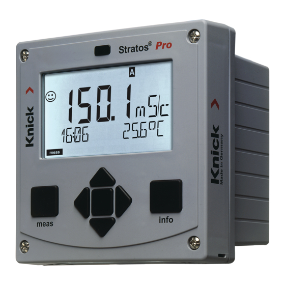
Page 12: Display In Measuring Mode
Display in Measuring Mode The MAIN DISPLAY is the display which is shown in measuring mode. To call the measuring mode from any other mode, hold the meas key depressed for at least 2 sec. meas key enter key meas By pressing meas briefly you can step through further displays such as tag number (TAG) or flow (L/h). -
Page 13: Selecting The Mode / Entering Values
Selecting the Mode / Entering Values To select the operating mode: 1) Hold meas key depressed (> 2 s) (measuring mode) 2) Press menu key: the selection menu appears 3) Select operating mode using left / right arrow key 4) Press enter to confirm the selected mode Selection menu Selected mode (blinks) - Page 14 Operating Modes / Functions Meas. mode TAG display CLK display (main display selectable) after 60 s after 60 s Pressing the menu key (down arrow) opens the selection menu. Select the menu group using the left/right arrow keys. Pressing enter opens a menu item. Press meas to return. Display of calibration data Display of sensor data Self test: RAM, ROM, EEPROM, module...
-
Page 15: Menu Structure Of Configuration
Overview of Configuration Menu Structure of Configuration The device provides 2 parameter sets “A“ and “B“. By switching between the param- eter sets you can adapt the device to different measurement situations, for example. Parameter set “B“ only permits setting of process-related parameters. The configuration steps are assigned to different menu groups. -
Page 16: Automatic Calibration (Calimatic)
Automatic Calibration (Calimatic) The AUTO calibration mode and the type of temperature detection are selected during configuration. Make sure that the buffer solutions used correspond to the configured buffer set. Other buffer solutions, even those with the same nominal values, may demonstrate a differ- ent temperature response. - Page 17 Automatic Calibration (Calimatic) Display Action Remark Stability check. Please note: The measured value Stability check can [mV] is displayed, “CAL2” be stopped after and “enter” are blinking. 10 sec (by pressing enter). However, this Calibration with the first buffer is terminated. reduces calibration Remove the sensor and accuracy.
-
Page 18: Product Calibration (Ph)
Product Calibration (pH) Calibration by sampling (one-point calibration). During product calibration the sensor remains in the process. The measurement process is only interrupted briefly. Procedure: 1) The sample is measured in the lab or directly on the site using a por- table meter. - Page 19 Product Calibration (pH) Display Action Remark The device returns to From the blinking measuring mode. CAL mode indicator you see that product calibration has not been terminated. Product calibration Display (3 sec) step 2: Now the device is in When the sample value HOLD mode.
- Page 20 Sensoface (Sensocheck must have been activated during configuration.) The smiley in the display (Sensoface) alerts to sensor problems ( defective sensor, sensor wear, defective cable, maintenance request). The permitted calibration ranges and the conditions for a happy, neutral, or sad Sensoface are summarized in the following table. Additional icons refer to the error cause.
-
Page 21: Display Problem
Sensoface Display Problem Status Asymmetry Asymmetry potential (zero) potential and and slope of the sensor are slope still okay. The sensor should be replaced soon. Asymmetry potential and slope of the sensor have reached values which no lon- ger ensure proper calibration. Replace sensor. - Page 22 Sensoface Display Problem Status Sensor wear High temperatures and pH values have caused a wear of over 80%. The sensor should be replaced soon. Wear is at 100%. Replace sensor. SENSOR WEAR Replace sensor AUTOCLAVE CYCLES Maximally permitted number of auto- OVERRUN claving cycles has been reached.
-
Page 23: Error Messages
Error Messages Info text Problem (is displayed in case of Error Possible causes fault when the Info key is pressed) Error in factory settings EEPROM or RAM defective This error message only occurs in the case of a total defect. The device must be repaired and recalibrated at the factory. - Page 24 Error Messages Info text Problem (is displayed in case of Error Possible causes fault when the Info key is pressed) Error in cal data * ORP display range violation < -1999 mV or > 1999 mV pH display range violation <...
- Page 25 Error Messages Info text Problem (is displayed in case of Error Possible causes fault when the Info key is pressed) Flow too low Flow too high Span Out1 configuration error Selected span too small Span Out2 configuration error Selected span too small Configuration error: Specifiable buffer set U1 I-Input configuration error...
-
Page 26: Specifications
Specifications pH input Input for digital sensors (RS485) Display range pH value –2.00 ... 16.00 –1999 ... 1999 mV Temperature –20.0 ... +200.0 °C I input (TAN) Current input 0/4 ... 20 mA / 50 Ω for external temperature signal Start/end of scale Configurable –20 ... - Page 27 Specifications Display LC display, 7-segment with icons Primary display Character height approx. 22 mm, unit symbols approx. 14 mm Secondary display Character height approx. 10 mm Text line 14 characters, 14 segments Sensoface 3 status indicators (happy, neutral, sad face) Mode Indicators meas, cal, conf, diag Further icons for configuration and messages...
- Page 31 Stratos Pro A201XMS PH pH測定 クイ ックスタート 最新の製品情報 : www.knick.de...
- Page 32 HART:一般的な用途 HART ターミナル 電源 4 ~ 20 mA 250 Ω 最低 19 V HART ターミナル HART ターミナル 4 ~ 20 mA...
- Page 33 安全上の注意 設置と試運転 警告 安全な設置、 試運転、 取り外しについて • 装置の設置/取り外しは、 該当する地域および国の規定に従って、 訓練を受けた有資 格者のみが行って ください。 • 設置にあたっては、 技術仕様と入力定格を確認して ください (ユーザーマニュアルを参照) 。 • 危険な場所に装置を設置する際は、 管理図面の仕様を確認して ください。 • 絶縁材をはがす際、 導体を傷つけないようにして ください。 • 試運転前に、 装置と他の機器の相互接続性を検証して ください。 • すべてのパラメーターは、 試運転前にシステム管理者が設定する必要があります。 一般的な注意事項 注意 安全な使用について この装置は、 最先端の技術を使用して開発および製造されており、 適用される安全規 制に準拠しています。 しかし、 状況によ っては操作時にオペレーターに危険が及んだり、 装置に損傷が生じたりする可能性があります。...
- Page 34 安全上の注意 保証期間内での返品 欠陥品を返品する前に、 メーカーにお問い合わせください (住所は表紙をご覧くださ い) 。 クリーニングした装置を指定された住所に発送して ください。 装置がプロセス液に接触した場合は、 返送前に除染/消毒する必要があります。 その場 合、 サービス担当者の健康と安全のために、 対応する証明書を添付して ください。 廃棄方法 各地域および国において適用される使用済み電気 ・ 電子機器の廃棄に関する規則を 遵守して ください。 危険な場所での使用について 運転時の注意事項 • このシリーズの装置は、 爆発危険領域での動作が承認されています。 爆発危険領域への電気機器の設置に関する現地の法令および基準を遵守して くだ さい。 詳し くは、 IEC 60079‑14、 EU指令2014/34/EU および 1999/92/EC (ATEX) 、 NFPA 70 (NEC) 、 ANSI/ISA‑RP12.06.01を参照して ください。 • 危険な場所に装置を設置する際は、...
- Page 35 組み立て パッケージ内容 輸送による損傷や不足品がないかご確認ください ! パッケージには以下が含まれています。 • フロン トユニッ ト、 リアユニッ ト、 部品バッグ • 仕様試験レポート • 関連文書 図 : ケースの組み立て 1) ジャンパー (3) 6) 封止インサート (1) 2) ワッシャー (1) 、 コンジッ ト取り 7) ゴムスペーサー (1) 付け用 : ケースとナッ トの間に 8) ケーブルグランド(3) ワッシャーを配置...
- Page 36 組み立て 取り付け方法、 寸法 1) ケーブルグランド(3) 2) ケーブルグランドまたは½インチ コンジッ トを通すための穴、 直径 21.5 mm。 (2箇所) コンジッ トのカップリングは含ま れていません ! 3) パイプ取り付け用の穴(4) 4) 壁面取り付け用の穴(2) 図 : 取り付け方法 (寸法単位はmm)
- Page 37 測定モード 電源に接続されると、 分析装置は自動的に 「測定」 モードになります。 別の操作モード (例 : 診断、 サービス) から測定モードを呼び出すに は、 meas キー を長押しして ください (2秒以上) 。 Sensoface 表示 有効なパラ (センサー状態) メータセッ ト (設定) 時間 (または流量) ディ スプレイ表示 OUT 1 : プロセス モード表示 変数など (測定) 測定モードにするに ディ スプレイ表 は、 measキーを長押 示OUT 2 :...
- Page 38 キーパッド キー 機能 meas • 1つ前のメニューに戻る • 直接測定モードに移行 (2秒以上長押し) • 測定モード : 他の表示 info • 情報取得 • エラーメッセージ表示 enter • 設定 : 入力を確定、 次の設定ステップへ • 校正 : プログラムを継続 menu • 測定モード : メニュー呼び出し • メニュー : 数値の増減 矢印キー 上/下 • メニュー : 選択 矢印キー...
- Page 39 ディスプレイ MEMO SENS 1 温度 13 情報あり 2 Sensocheck 14 ホールドモード有効 3 インターバル/応答時間 15 メイン画面 4 センサーデータ 16 サブ画面 5 使用しない 17 enterキーを押して進む 6 上限、 下限の表示 : 18 ISM センサー 限界 1 または限界 2 19 診断 7 アラーム 20 設定モード 8 サービス...
- Page 40 測定モード画面 メイン画面は、 測定モードで表示され る画面です。 他の操作モード (診断、 サービスなど) から測定モードに切り替えるには、 meas キーを2秒以上長押しします。 meas キー enter キー meas meas を短押しすると、 TAG番号 (TAG) や流量 (L/h) などの他の画面 を表示できます。 こうした表示の色は水色です。 60秒ほどで、 メイン画面に戻ります。 meas enter キーを押して、 表 示中の画面をメイン画 enter 面として選択します – セカンダリディ スプレイには 「MAIN DISPLAY – NO (メイン画面 - いいえ)...
- Page 41 モードの選択/値の入力 操作モードを選択するには : 1) meas キー を長押しします (2秒以上) ( 測定モード) 2) menuキーを押すと、 選択メニューが表示されます 3) 左/右の矢印キーで、 操作モードを選択します 4) enterキーを押し、 選択したモードを確定します 選択メニュー 選択したモード (点滅) 値を入力するには : 5) 数値を選択 : 左/右の矢印キー 6) 数値を変更 : 上/下の矢印キー 7) enterキーを押して、 入力を確定します...
- Page 42 操作モード/機能 測定モード タグ表示 時計表示 (メイン画面選 択可能) 60秒後 60秒後 menu キー (下矢印) を押すと、 選択メニューが表示されます。 左/右の矢印キーでメニューグループを選択します。 enterキー を押すと、 メニュー項目が開きます。 measキーを押すと戻ります。 ▶ 校正データの表示 センサーデータの表示 自己診断 : RAM、 ROM、 EEPROM、 モジュール 100件のイベン トとその日付 測定値の表示 (mV_pH、 mV_ORP、 温度、 ガラス電極電気抵 抗、 比較電極) ソフ トウェアバージョン、 モデル名、 シリアルナンバーの表示 ▶...
- Page 43 設定概要 設定のメニュー構成 本装置には2つのパラメータセッ ト 「A」 「 B」 があります。 パラメータセッ トを切り替え ることで、 例えば装置を違う測定状況に適用させることができます。 パラメータセッ ト 「B」 は、 プロセス関連のパラメータ設定のみ可能です。 設定ステップは、 異なるメニューグループに分かれています。 左/右の矢印キーで、 メニューグループ間を移動することができます。 各メニューグループには、 パラメータ設定用のメニュー項目があります。 enter キーを押すと、 メニュー項目が開きます。 矢印キーを使って値を編集します。 enterキーを押し、 設定を確定/保存します。 測定に戻る : meas キーを長押しします (2秒以上) 。 メニューグル メニュー項目の メニューグループ コード ディスプレイ ープの選択...
- Page 44 自動校正 (Calimatic) AUTOを選択すると、 校正液セッ トを自動認識し、 温度テーブルが適 用されます。 使用する校正液が、 設定された校正液セッ トに対応して いることを確認して ください。 他の校正液は、 公称値が同じであって も、 温度応答が異なる場合があり、 測定エラーの原因になります。 ディスプレイ アクション 備考 校正を選択します。 enterキーを押して進 みます。 校正準備完了。 表示 (3秒) 砂時計が点滅します。 装置がホールド 校正方法の選択 : モードになりました。 CAL_PH enterキーを押して進 みます。 センサーと温度プロー 温度手動入力が設 ブを取り外して洗浄し、 定されている場合 最初の校正液に (任意 は、...
- Page 45 自動校正 (Calimatic) ディスプレイ アクション 備考 安定性チェ ック。 ご注意ください : 測定値[mV]が表示され、 安定性チェ ックは10 「CAL2」 と 「enter」 が点滅 秒後に停止できます します。 (enterキーを押し 最初の校正液を使用した ます)。 ただし、 校正 校正が終了します。 最初の の精度が低くなりま 校正液からセンサーと温度 す。 1点校正用ディ ス プローブを取り外し、 十分 プレイ : にすすぎます。 矢印キーを使って値を選択 します。 • END (1点校正) •...
- Page 46 合わせこみ校正(pH) サンプリングによる校正 (1点校正) 。 合わせこみ校正の間は、 センサーはプロセスに残ったままです。 測定プロセスは短時間だけ中断されます。 手順 : 1) サンプルは、 ラボで、 またはポータブルメーターを使用して現場で直 接測定されます。 確実な校正を行うには、 サンプル温度は測定済み プロセス温度に対応していなければなりません。 サンプリング中、 装置は現在測定中の値を保存してから測定モード に戻ります。 「 校正」 モード表示が点滅します。 2) 2つ目のステップでは、 測定済みサンプル値を装置に入力します。 保 存済みの測定値と入力されたサンプル値の違いから、 装置が新しい ゼロ点を計算します。 サンプルが無効な場合、 サンプリング中に保存した値に代えられます。 その場合、 古い校正値は保存されます。 その後、 新しい合わせこみ校正を開始できます。 ディスプレイ アクション 備考 P_CAL(合わせこみ校 無効なコードが入力...
- Page 47 合わせこみ校正(pH) ディスプレイ アクション 備考 装置が測定モードに戻 CALモード表示の点 ります。 滅から、 合わせこみ 校正が終了していな いことがわかります。 合わせこみ校正 ステッ 表示 (3秒) プ 2 : 装置がホールド サンプル値が決定した モードになりました。 ら、 合わせこみ校正を 再度開きます (P_CAL)。 保存値が表示され (点 滅) 、 測定済みのサンプ ル値に上書きできます。 enterキーを押して進 みます。 新しいゼロ点の表示 校正を繰り返すに (25°C基準) 。 は : REPEATの後に Sensoface が有効です。...
- Page 48 Sensoface (設定時にSensocheckを有効化しておく必要があります。 ) ディ スプレイのスマイリー (Sensoface) は、 センサーの問題 (センサ ーの不具合、 センサーの摩耗、 ケーブルの不良、 メンテナンス要求) を 警告します。 許容される校正の範囲と、 嬉しい、 中立、 悲しい状況の Sensofaceの条件を次の表にまとめました。 それ以外のアイコンは、 エラーの原因を示します。 Sensocheck Sensocheck は継続的にセンサーとワイヤリングをモニターしています。 閾値を超えると、 Sensofaceが 「悲しい」 状態になり、 対応するアイコン が点滅します。 Sensocheck メッセージはエラーメッセージ Err 15 (ガラス電極) ま たはErr 16 ( 参照電極) としても出力されます。 表示のバックライ トが 赤になり、...
- Page 49 Sensoface ディスプレイ 問題 状態 ゼロ点と センサーのゼロ点 (ゼロ) お スロープ よびスロープはまだ大丈夫 ですが、 センサーは早めに取り替え て ください。 ゼロ点およびスロープが、 適 正な校正を保証できない値 に達しました。 センサーを取 り替えて ください。 校正タイ すでに80%の校正期限を過 マー ぎました。 校正期限を超えています。 センサー センサーと接続を確認して の不具合 ください (Err 15とErr 16の エラーメッセージをご覧くだ さい) 。 応答時間 センサーの応答時間が増加 しました。 センサーは早めに取り替え て...
- Page 50 Sensoface ディスプレイ 問題 状態 セン 高温とpH値により、 80% サー摩耗 以上摩耗しています。 センサーは早めに取り替 えて ください。 摩耗は100%です。 センサーを取り替えて くだ さい。 センサー摩耗 センサーを取り替えて ください オートクレーブ サイクル オートクレーブサイクルの回数が最大 超過 許容値を超えました。 センサーを交換するか、 オートクレーブ カウンターを進めます。 SIP サイクル超過 滅菌サイクルの回数が最大許容値を超 えました。 センサーを交換するか、 SIP カウン ターを進めます。 CIP サイクル オーバーラン クリーニングサイクルの回数が最大許 容値を超えました。 センサーを交換するか、...
- Page 51 エラーメッセージ テキストメッセージ トラブル エラー (トラブル発生時にinfo 考えられる原因 キーを押すと表示されます) 工場出荷時設定のエラー EEPROMまたはRAMの故障 このエラーメッセージは、 完全 な故障の場合にのみ表示され ます。 工場で修理 ・ 再校正する必 要があります。 設定または校正データの エラー 装置のプログラムのメモリーエ ラー設定または校正データに 不具合があります。 設定と校正 をやり直して ください。 「Memosens」 がセンサーの選 択で選択されていません 「Memosens」 がセンサーの選 択で選択されていません システムエラー 再起動が必要です。 エラーが続く場合は、 修理に出 して ください。 pH センサー センサーの不具合 センサーが接続されていません...
- Page 52 エラーメッセージ テキストメッセージ トラブル エラー (トラブル発生時にinfo 考えられる原因 キーを押すと表示されます) 校正データのエラー* ORP表示レンジ超過 < -1999 mV または > 1999 mV pH 表示レンジ超過 < -2 または > 16 mV レンジ 温度レンジ超過 Sensocheck ガラス電極 Sensocheck 比較電極 負荷エラー 出力電流 1 < 0 (3.8) mA 出力電流 1 > 20.5 mA 出力電流...
- Page 53 エラーメッセージ テキストメッセージ トラブル エラー (トラブル発生時にinfo 考えられる原因 キーを押すと表示されます) Flow (流量) が少なすぎる Flow (流量) が多すぎる Out1 出力間隔設定エラー 出力間隔が狭すぎます Out2 出力間隔設定エラー 出力間隔が狭すぎます 設定エラー : 指定可能な校正液セッ トU1 I-入力設定エラー...
- Page 54 仕様 pH 入力 デジタルセンサー入力 (RS485) 表示レンジ pH 値 –2.00 ~ 16.00 –1999 ~ 1999 mV 温度 –20.0 ~ +200.0 °C 電流入力0/4 ~外部温度信号用に20 mA / 50Ω I 入力 (TAN) スケールの始点/終点 設定可能–20 ~ +200°C 特性 線形 測定誤差 電流値の<1%+ 0.1 mA 1) 2) ホールド入力...
- Page 55 仕様 ディスプレイ LCディ スプレイ、 アイコン付き7セグメン ト メイン画面 文字の高さ約22 mm、 単位記号約 14 mm サブ画面 文字の高さ約10mm テキスト行 14文字、 14セグメン ト Sensoface 3つの状態を表示 (嬉しい、 中立、 悲しい顔) モード表示 meas, cal, conf, diag 設定とメッセージ用のその他のアイコンあり アラーム表示 ディ スプレイの点滅、 赤色バックライ ト 防爆 管理図面を参照 EN 61326-1 ( 一般要件) 干渉電波...
- Page 56 Knick Elektronische Messgeräte GmbH & Co. KG Headquarters Beuckestraße 22 14163 Berlin, Germany Phone: +49 30 80191-0 Fax: +49 30 80191-200 info@knick.de www.knick.de Local Contacts www.knick-international.com Copyright 2020 • Subject to change Version: 3 This document was published on March 30, 2020 The latest documents are available for download on our website under the corresponding product description.
Need help?
Do you have a question about the Stratos Pro A201XMS PH and is the answer not in the manual?
Questions and answers