Knick Protos II 4400 Series User Manual
Process analysis system
Hide thumbs
Also See for Protos II 4400 Series:
- User manual (112 pages) ,
- Installation manual (2 pages) ,
- Installation manual (2 pages)

Related Manuals for Knick Protos II 4400 Series


Summary of Contents for Knick Protos II 4400 Series
- Page 1 Protos II 4400 (X) Process Analysis System Protos II PN4400-095 User Manual Communication Module Communication Unit for PROFINET Read before installation. Keep for future use. www.knick.de...
-
Page 2: Returns
Returns Clean and securely package the product before returning it to Knick Elektronische Messgeräte GmbH & Co. KG if required. If there has been contact with hazardous substances, the product must be decontaminated or disinfected prior to shipment. The consignment must always be accompanied by a corresponding return form to prevent service employees being exposed to potential hazards. -
Page 3: Table Of Contents
Table of Contents PN4400-095 Module Returns ............................2 Disposal ............................2 Safety ........................ 5 Intended Use ..........................5 Abbreviations ....................6 Firmware Version ..................... 8 PROFINET Technology ..................9 Package Contents ..................10 Terminal Plate ....................10 Inserting the Module ..................11 PROFINET Installation ................... - Page 4 Table of Contents PN4400-095 Module Specifications ....................48 Measured Values Available for PROFINET ........... 50 PH Module Types ........................50 pH/pH Calculation Blocks......................51 OXY Module Types ........................52 Calculation Block .....................53 COND/CONDI Module Types ....................54 COND / COND Calculation Block ..................55 Index ....................... 56...
-
Page 5: Safety
It features two RJ45 Ethernet sockets and can therefore be connected in a ring or star topology. The module is only intended for operation in ordinary (non-hazardous) locations. Maintenance Protos modules cannot be repaired by the user. For inquiries regarding module repair, please contact Knick Elektronische Messgeräte GmbH & Co. KG at www.knick.de. -
Page 6: Abbreviations
Abbreviations Analog input. Function block for providing input data. Analog output. Function block for processing output data. Application relation CC-A/B/C/D Conformance classes Communication relation Discovery and basic configuration protocol: DCP is part of the PROFINET protocol and makes it possible to find and configure a device. If the device’s MAC address and name of station are recog- nized by a process control system (PCS), the PCS can allocate the IP address to the device using DCP. - Page 7 Abbreviations PROFINET Process field network Received data Real time: channel for transmitting process data TCP/IP Transmission control protocol/Internet protocol: Protocols that form the basis for data exchange on the Internet and in other networks Transmitted data Totally Integrated Automation: Siemens provides automation tools on its TIA Portal.
-
Page 8: Firmware Version
Firmware Version PN4400-095 Module Firmware Firmware version 01.xx.xxx Module Compatibility Protos II 4400 with FRONT firmware version 01.01.xx or higher Query Current Device Firmware/Module Firmware When the device is in measuring mode: Press the menu key, open Diagnostics menu: Device Description Menu Display Action Device hardware and firmware... -
Page 9: Profinet Technology
PROFINET Technology PROFINET is an open industrial standard for safe and fast data transmission via the industrial Ethernet. The standard was created and is managed by the PROFIBUS user organization PROFIBUS and PROFINET International (PI). The PROFINET standard evolved from PROFIBUS – a fieldbus communication standard to support automation technology. -
Page 10: Package Contents
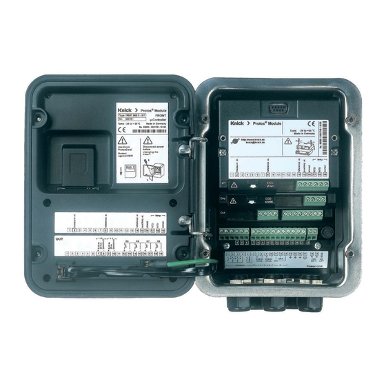
Package Contents • Communication module • Installation Guide • Test Report 2.2 acc. to EN 10204 • Adhesive label with terminal assignments and MAC address Terminal Plate Protos II Module Protos II Module Type PN 4400-095 -20 to +55 °C Profinet Type PN 4400-095... -
Page 11: Inserting The Module
Inserting the Module CAUTION! Electrostatic discharge (ESD). The modules’ signal inputs are sensitive to electrostatic discharge. Take measures to protect against ESD before inserting the module and wiring the inputs. Note: The PN4400-095 module must be installed in slot 2. 1) Switch off the power supply to the device. -
Page 12: Profinet Installation
PROFINET Installation Wiring RJ45 Ethernet Sockets 1 and 2 Name Description Transmitted data + Transmitted data - Received data + Received data - Transmitted data + Transmitted data - Received data + Received data -... - Page 13 PROFINET Installation The module can be connected in a ring or star topology. Ring Topology In this topology, terminal devices and control systems are connected in series. In addition, the first and last devices are connected to the control system, there- by forming a ring.
-
Page 14: System Integration
System Integration Initial Commissioning PROFINET devices are identified in the network using the following parameters: IP address, MAC address, and device name (Name of Station). • IP address on delivery: 0.0.0.0 • For the MAC address, see the terminal plate. •... -
Page 15: Installing The Gsdml File
A PROFINET device master file (GSDML file) is required for system integration. The latest version of the GSDML file is available in the downloads section of the Knick website. The procedure for installing the GSDML file varies depending on the engineer- ing tool used. -
Page 16: Configuration On The Tia Portal
Configuration on the TIA Portal 1) In the PN4400-095 module hardware catalog, select the following: “Other Field Devices PROFINET IO Sensors Knick Analysis Protos 4400-PN095” 2) Drag and drop “Protos 4400-PN095” into the network view and position it next to the CPU icon (see figure below). - Page 17 System Integration...
- Page 18 System Integration Assigning Device Name and IP address Online 1) Connect the device to the PROFINET network. 2) TIA Portal: Project Navigation Devices Online Access. 3) Select the device’s network interface. 4) Double-click on “Update Accessible Devices”. Accessible devices are shown with their MAC addresses. 5) Select the device.
-
Page 19: Replacing The Device
Replacing the Device By using the neighborhood detection function, the control system assigns the PROFINET device name and the IP address to the newly added device (PN4400-095 module). Note: All current settings are automatically applied if only the PN4400-095 module is replaced. If the entire Protos II 4400 device is replaced, the remaining device parameter settings are not automatically applied. -
Page 20: Resetting The Device
Resetting the Device Resetting the Device Parameters In the Protos device menu: Parameter Setting System Control Restore Factory Settings The reset function in the device menu does not reset the PROFINET network settings. In the TIA Portal: Functions Reset to factory settings The reset function via PROFINET in the device menu does not reset the Protos to its factory settings. -
Page 21: Function Blocks (Ai, Ao)
Function Blocks (AI, AO) The module provides 20 analog input blocks (AI 1 ... AI 20) and one analog output block. The function blocks have fixed positions in the GSDML file and cannot be removed. This makes it possible to add additional process variables to the cyclic I/O data in the device menu without having to adjust the PROFINET project with the engineering tool. -
Page 22: Cyclic Data Transfer
Cyclic Data Transfer Cyclic data transfer has two transport directions: • Input data Data transfer from the field device (Device) to the process control system (Controller): Input data are provided by the analog input function blocks; see p. 23 ff. •... -
Page 23: Analog Input Blocks
Analog Input Blocks The module provides 20 analog input blocks (AI 1 ... AI 20). The measured values to be transmitted by an AI are assigned on the device; see the following pages. - Page 24 Analog Input Blocks Assignment of process variables to analog input blocks on the device Note: Function check (HOLD) active Menu Display Action Open Parameter Setting From the measuring mode: Menu Selection Press menu key to select menu. Select Parameter Setting using arrow keys, press enter to confirm.
- Page 25 Analog Input Blocks Menu Display Action Assign process variables to the separate analog input blocks. Measured Values (Admin.) The process variables available AI 1 AI 2 Conductance depend on the installed modules. AI 3 Effective Resistance For available measured values, AI 4 Cell Constant AI 5 Install.
-
Page 26: Profinet Commands
PROFINET Commands Slot Subslot Index Access Parameters Description Device settings: rd/wr LOCAL_OP_ENABLE Local Operation Enable / Key Lock 1 byte ENUM Byte = 0 (Key Lock) Byte = 1 (Local Operation Enable) Device configuration: DEVICE_CONFIG Current module / sensor channel configuration in Protos 4 byte flag register Flag register[0]:... - Page 27 PROFINET Commands Slot Subslot Index Access Parameters Description Input frame (cyclic data: device -> controller) Measured value 1: From module n channel n 4 byte FLOAT – measured value 1 byte U8 – status Measured value 2: From module n channel n 4 byte FLOAT –...
- Page 28 PROFINET Commands Slot Subslot Index Access Parameters Description AI14 Measured value 14: From module n channel n 4 byte FLOAT – measured value 1 byte U8 – status AI15 Measured value 15: From module n channel n 4 byte FLOAT – measured value 1 byte U8 –...
- Page 29 PROFINET Commands Slot Subslot Index Access Parameters Description CAL_PRD_STORED_ 1A: Query saved sample value VAL_1A 4 byte FLOAT Sample value rd/wr CAL_PRD_TRUE_ 1A: Transfer lab value, calculate calibration VAL_1A values 4 byte FLOAT Lab value: Triggers step 2 prod. cal. CAL_PRD_STEP_1A 1A: Current product calibration step 1 byte ENUM...
- Page 30 PROFINET Commands Slot Subslot Index Access Parameters Description Product calibration module 1 channel C: SNS_DESC_1C 1C: Sensor ID See product calibration module 1 channel A rd/wr CAL_PRD_MODE_1C 1C: Product calibration mode See product calibration module 1 channel A rd/wr CAL_PRD_SAMPLE_1C 1C: Take sample value, cancel See product calibration module 1 channel A CAL_PRD_STORED_ 1C: Read saved sample value...
- Page 31 PROFINET Commands Slot Subslot Index Access Parameters Description Product calibration module 2 channel B: SNS_DESC_2B 2B: Sensor ID See product calibration module 1 channel A rd/wr CAL_PRD_MODE_2B 2B: Product calibration mode See product calibration module 1 channel A rd/wr CAL_PRD_SAMPLE_2B 2B: Take sample value, cancel See product calibration module 1 channel A CAL_PRD_STORED_ 2B: Read saved sample value...
- Page 32 PROFINET Commands Slot Subslot Index Access Parameters Description Product calibration module 3 channel A: SNS_DESC_3A 3A: Sensor ID See product calibration module 1 channel A rd/wr CAL_PRD_MODE_3A 3A: Product calibration mode See product calibration module 1 channel A rd/wr CAL_PRD_SAMPLE_3A 3A: Take sample value, cancel See product calibration module 1 channel A CAL_PRD_STORED_ 3A: Read saved sample value...
- Page 33 PROFINET Commands Slot Subslot Index Access Parameters Description Product calibration module 3 channel C: SNS_DESC_3C 3C: Sensor ID See product calibration module 1 channel A rd/wr CAL_PRD_MODE_3C 3C: Product calibration mode See product calibration module 1 channel A rd/wr CAL_PRD_SAMPLE_3C 3C: Take sample value, cancel See product calibration module 1 channel A CAL_PRD_STORED_ 3C: Read saved sample value...
-
Page 34: Product Calibration
Product Calibration If the sensor cannot be removed – e.g., for sterility reasons – calibration can be performed by sampling (“product calibration”). For a description, see the user manual for the measuring module. 11 ... 13 1 ... 3 62 CAL_PRD_MODE_nX Simple Unsigned8 Static Read / Contained /... -
Page 35: Key Lock
Product Calibration Product Calibration Procedure Parameters Description CAL _PRD _MODE Calibration mode: pH, Cond, Condl: 0 is the only admissible value Oxy: 0: Saturation, 1: Concentration CAL_PRD _ SAMPLE Take a sample. Writing 1 to this parameter causes Protos to save the current process value for later correction. -
Page 36: Analog Output Block
Analog Output Block Pressure Compensation via Bus (AO1) Menu Display Action Oxy module parameter setting Select “Pressure Correction” in the set- Module OXY 3400-067 (Admin.) tings for the oxygen module Input Filter Sensor Data Cal Presettings Pressure Correction Salinity Correction Messages Back Lock... -
Page 37: Diagnostic Functions
Diagnostic Functions Menu Display Action Open the Diagnostics menu From the measuring mode: Menu Selection Press menu key to select menu. Select Diagnostics using arrow keys, press enter to confirm. Diagnostics Lingua/ 语言 The “Diagnostics” menu gives an overview of all functions available. Diagnostics Functions which have been set as Measuring Point Description... - Page 38 Diagnostic Functions Menu Display Action PROFINET diagnostics The values below indicate functioning PROFINET Module PROFINET communication: Module Diagnostics Network Information Stack State 0x000000FB PROFINET Diagnostics Last Error 0x00000000 PROFINET Monitor Phy Link State Back Set Favorite Config State Application Comm State Operate Comm Error 0x00000000...
-
Page 39: Measured Value Status
Measured Value Status Description Hex value / NE107 signal display BAD Maintenance Alarm 0x24 ... 0x27 Failure BAD (F) BAD Process Related 0x28 ... 0x2B Failure BAD (F) UNCERTAIN Invalid Process 0x78 ... 0x7B Out of specification Condition UNCERTAIN Maintenance 0x68 ... 0x7B Maintenance request Demanded GOOD Maintenance 0xA8 ... 0xAB Maintenance request Demanded... -
Page 40: Communication Status
Communication Status Display Active PROFINET communication is indicated by the PN icon in the device’s status display. LEDs (at Ethernet socket) Name Meaning Yellow TX/RX Receive/transmit Off Device does not transmit/ receive any Ethernet frames Device transmitting/receiving (flickers) Ethernet frames Green LINK Connection... -
Page 41: I&M Functions
The PN4400-095 module supports the following standardized I&M functions. I&M functions provide device data in a manufacturer-independent format. Data transfer is acyclic. I&M_0: Index 0xAFF0, Access: Read only Element Name Description VendorIDHigh VendorIDLow 0x61 (97) = Knick Order ID 096680 IM_Serial_Number IM_Hardware_Revision IM_Software_Revision IM_RevisionCounter IM_Profile_ID IM_Profile_Specific_Type 5 (Generic Device). - Page 42 I&M Functions I&M_3: Index 0xAFF3, Access: Read/Write Element Name Data type Description IM_Descriptor VisibleString(54) Description Presetting as in Protos device menu: Parameter SettingSystem ControlMeas. Point DescriptionAnnotation...
-
Page 43: Profinet Diagnostic Information
PROFINET Diagnostic Information Diagnostic events are reported to the PROFINET controller and displayed, for example, in the TIA Portal. Every event generates an entry in the diagnostics buffer. Details of the event can be displayed by double-clicking on the red icon by the controller icon (see following page). - Page 44 PROFINET Diagnostic Information Diagnostics Buffer Menu (TIA Portal) Transmission of diagnostic information can be enabled or disabled in the Protos device menu: Parameter Setting PN 4400-095 Module Alarms/Diagnostics Module PN 4400-095 (Admin.) Alarms/Diagnostics Measured Values Back...
- Page 45 PROFINET Diagnostic Information Overview Source Error Extended State Maintenance Error Text Type Error Type FRONT Error Firmware Error FRONT Error System Failure FRONT Error FRONT Indicates an Error FRONT Error Internal Bus Error FRONT Error Adjustment Data FRONT Error Configuration Data Loss FRONT Error Value out of Specification...
- Page 46 PROFINET Diagnostic Information Overview Source Error Extended State Maintenance Error Text Type Error Type MODULE / Alarm Value out of Range SENSOR MODULE / Alarm Man. Value out of Specification SENSOR MODULE / Alarm New Sensor – Adjustment Required SENSOR MODULE / Alarm TTM Maintenance Timer...
-
Page 47: Error Messages/Troubleshooting
Error Messages/Troubleshooting Error/message Possible causes Remedy (Diagnostics menu: Message List) Display is blank. FRONT or BASE power supply Check the power supply. interrupted. Input fuse has tripped. Replace the fuse (500 mA T). Display switch-off is active. Disable display switch-off. No measurement, no error Module not plugged in correctly. -
Page 48: Pn4400-095 Module
Specifications PN4400-095 Module PROFINET IO specification V2.34 Conformance class B (CC-B) Network load class Vendor ID 0x61 (= Knick) Device ID 0x0020 Min. cycle times 1 ms Identification & maintenance I&M1-3, 0 Serial interface standard 100BASE-TX (IEEE 802.3, IEC 61158, IEC 61784) Number of AIs... - Page 49 Specifications Protos II 4400 General Specifications RoHS conformity According to EU directive 2011/65/EU EN 61326-1, EN 61326-2-3 NAMUR NE 21 Emitted interference Industrial applications Interference immunity (EN 55011 Group 1 Class A) Industrial applications Lightning protection to EN 61000-4-5, Installation class 2 Rated operating conditions (module installed) Ambient temperature...
-
Page 50: Measured Values Available For Profinet
Measured Values Available for PROFINET Measured values than can be assigned to analog input blocks (AIs) Note: Not all values can be used. The available selection depends on the sensor type used. PH Module Types Measured value Unit of measurement Measurement status pH value Variable... -
Page 51: Ph/Ph Calculation Blocks
Measured Values Available for PROFINET Measured values than can be assigned to analog input blocks (AIs) pH/pH Calculation Blocks Measured value Unit of measurement Measurement status Temperature diff. °C or °F Variable pH diff. Variable pH voltage diff. Variable ORP diff. Variable... -
Page 52: Oxy Module Types
Measured Values Available for PROFINET Measured values than can be assigned to analog input blocks (AIs) Note: Not all values can be used. The available selection depends on the sensor type used. OXY Module Types Measured value Unit of measurement Measurement status Saturation %air Variable... -
Page 53: O 2 / O 2 Calculation Block
Measured Values Available for PROFINET Measured values than can be assigned to analog input blocks (AIs) Measured value Unit of measurement Measurement status SIP counter Fixed (0x80) CIP counter Fixed (0x80) Autoclaving counter Fixed (0x80) Impedance kΩ Variable Calculation Block Measured value Unit of measurement Measurement status... -
Page 54: Cond/Condi Module Types
Measured Values Available for PROFINET Measured values than can be assigned to analog input blocks (AIs) Note: Not all values can be used. The available selection depends on the sensor type used. COND/CONDI Module Types Measured value Unit of measurement Measurement status Conductivity µS/cm... -
Page 55: Cond / Cond Calculation Block
Measured Values Available for PROFINET Measured values than can be assigned to analog input blocks (AIs): COND / COND Calculation Block Measured value Unit of measurement Measurement status Temperature diff. °C or °F Variable Conductivity diff. µS/cm Variable Resistivity diff. MΩ... -
Page 56: Index
Index PN4400-095 Module Abbreviations ..........................6 Alarms/diagnostics ......................... 44 Analog input blocks ....................... 23 Analog output block ......................36 Assignment of process variables to analog input blocks ......... 24 Commissioning ........................14 Communication status ......................40 Configuration ..........................16 Conformance classes ....................... 9 Cyclic commands, coding .................... - Page 57 Index PN4400-095 Module I&M functions ........................... 41 Initial commissioning ......................14 Inserting the module ......................11 Installation, insert module ....................11 Installation, PROFINET ......................12 Intended use ..........................5 IP address ........................... 37 Key lock ............................35 MAC address, description....................... 6 MAC address, Diagnostics menu ..................
- Page 58 Index PN4400-095 Module Rated operating conditions....................49 Replacing the device......................19 Reset to factory settings ....................... 20 Returns ............................2 Ring topology ........................... 13 Safety instructions ........................5 Serial number ..........................8 Specifications ..........................48 Stack, firmware version ......................8 Star topology ..........................
- Page 60 Knick Elektronische Messgeräte GmbH & Co. KG Headquarters Beuckestraße 22 • 14163 Berlin Germany Phone: +49 30 80191-0 Fax: +49 30 80191-200 info@knick.de www.knick.de Local Contacts www.knick-international.com Copyright 2020 • Subject to change Version: 1 This document was published on November 13, 2020 The latest documents are available for download on our website under the corresponding product description.
Need help?
Do you have a question about the Protos II 4400 Series and is the answer not in the manual?
Questions and answers