
Related Manuals for Knick Stratos Pro A4..MSPH series


Summary of Contents for Knick Stratos Pro A4..MSPH series
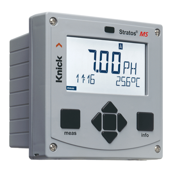
- Page 1 Stratos®Pro A4... MSPH Instruction Manual Latest Product Information: www.knick.de...
- Page 2 Warranty Warranty Defects occurring within 3 years from delivery date shall be remedied free of charge at our plant (carriage and insurance paid by sender). Sensors, fi ttings, and accessories: 1 year. Subject to change without notice. Return of Products Under Warranty Please contact our Service Team before returning a defective device.
-
Page 3: Documents Supplied
Spanish, Portuguese, Swedish, and Dutch. Short Instructions ......3 Kurzübersicht ......... 15 More languages on CD-ROM and Quick Start ........27 Быстрый старт ......39 on our website: www.knick.de Inicio rápido ........51 Início rápido ........63 • Installation and commissioning 快速启动 ........75 •... -
Page 4: Table Of Contents
Contents Documents Supplied ..............3 Introduction ..................7 Intended Use ....................7 Safety Information ................. 8 Safety Precautions for Installation ............9 Registered Trademarks .................9 Overview of Stratos Pro A4... MSPH..........10 Assembly ..................11 Package Contents ..................11 Mounting Plan, Dimensions ..............12 Pipe Mounting, Protective Hood ............13 Panel Mounting .....................14 Installation ..................15 Installation Instructions ................15... - Page 5 Contents Parameter Set Selection ..............34 Parameter Set A/B ..................34 Configuration ................35 Configuration (Original for Copy) ............39 Sensor .......................42 Current Output 1 ..................50 Current Output 2 ..................56 Temperature Compensation ..............58 Alarm .........................60 Limit Function ....................62 Pulse Length / Pulse Frequency Controller.........71 Controller .......................72 WASH Contact ....................76 Time and Date ....................78...
- Page 6 Contents Product Line and Accessories ..........112 Specifications ................113 Buffer Tables ................120 -U1- Specifiable Buffer Set ..............129 Error Handling ................132 Error Messages ................133 Sensoface ..................136 FDA 21 CFR Part 11 ..............139 Electronic Signature – Passcodes ............139 Audit Trail ..................... 139 Index .....................140 Passcodes ..................148...
-
Page 7: Introduction
Introduction Intended Use The Stratos Pro A4... MSPH is used for pH/mV, ORP, and temperature measurement in industry, environment, food processing, and sewage treatment. The sturdy molded enclosure can be fi xed into a control panel or mounted on a wall or at a post. The protective hood, which is avail- able as accessory, provides additional protection against direct weather exposure and mechanical damage. -
Page 8: Safety Information
Safety Information Safety information – Be sure to read and observe the following instructions! The device has been manufactured using state of the art technology and it complies with applicable safety regulations. When operating the device, certain conditions may nevertheless lead to danger for the operator or damage to the device. -
Page 9: Safety Precautions For Installation
Safety Information Safety Precautions for Installation • electrical installation shall conform to the national regulations for electrical installations and/or other applicable national or local codes or regulations. • The power supply shall be disconnectable from the device by a two-poled circuit breaker. •... -
Page 10: Overview Of Stratos Pro A4
Overview Overview of Stratos Pro A4... MSPH + Output 1 / HART Output 1 Power supply RS 485 RS 485 A – Output 1 / HART Output 2 RS 485 B + Output 2 GND/Shield – Output 2 REL 1 REL 1/2 REL 2 Alarm... -
Page 11: Assembly
Assembly Package Contents Check the shipment for transport damage and completeness! The package should contain: • Front unit, rear unit, bag containing small parts • Specific test report • Documentation (cf Pg 3) • CD-ROM Fig.: Assembling the enclosure Jumper (3 x) Sealing insert (1 x) Washer (1 x), for conduit Rubber reducer (1 x) -
Page 12: Mounting Plan, Dimensions
Assembly Mounting Plan, Dimensions Cable gland (3 x) Knockouts for cable gland or ½" conduit, 21.5 mm dia. (2 knockouts) Conduits not included! Knockout for pipe mounting (4 x) Knockout for wall mounting (2 x) Fig.: Mounting plan (All dimensions in mm!) -
Page 13: Pipe Mounting, Protective Hood
Assembly Pipe Mounting, Protective Hood ø40...ø60 Hose clamp with worm gear drive to DIN 3017 (2 x) Pipe-mount plate (1 x) For vertical or horizontal posts or pipes Self-tapping screw (4 x) Fig.: ZU 0274 pipe-mount kit (All dimensions in mm!) Fig.: ZU 0737 protective hood for wall and pipe mounting (All dimensions in mm!) -
Page 14: Panel Mounting
Assembly Panel Mounting <30 Circumferential sealing (1 x) Screw (4 x) Position of control panel Span piece (4 x) Threaded sleeve (4 x) Cutout 138 x 138 mm (DIN 43700) 1...22 1...22 Fig.: ZU 0738 panel-mount kit (All dimensions in mm!) -
Page 15: Installation
Installation Installation Instructions • Installation of the device must be carried out by trained experts in accordance with this instruction manual and as per applicable local and national codes. • Be sure to observe the technical specifi cations and input ratings during installation! •... -
Page 16: Rating Plates / Terminal Assignments
Installation Rating Plates / Terminal Assignments Fig.: Terminal assignments of Stratos Pro A4... Fig.: Stratos Pro A401N-MSPH rating plate at bottom of front Fig.: Stratos Pro A411N-MSPH rating plate at bottom of front... -
Page 17: Power Supply, Signal Lines
Power Supply, Signal Lines Connect the power supply for Stratos Pro A401/A411 MSPH to terminals 21 and 22. (24 ... 230 V AC, 45 ... 65 Hz / 24 ... 80 V DC) Assignments 1 (BN) Power suppy 2 (GN) RS 485 A 3 (YE) RS 485 B... -
Page 18: Sensor Connection
Sensor Connection Connect the sensor lines with the sensor connection (RS-485, terminals A...K). Areas for placing the screwdriver to pull out the terminals Sensor connection RS-485 Fig.: Terminals, device opened, back of front unit... -
Page 19: Wiring Examples
Wiring Examples Example 1: Measuring task: pH/ORP, temp, glass impedance, ref. impedance Sensors ( example): SE 533/1-ADIN (Knick) Cable (example): CA/003-NAADIN11 (Knick) - Page 21 Wiring Examples Example 2: Measuring task: pH/ORP, temp, glass impedance Sensors (example): SE531/1-NMSN (Knick)
-
Page 22: Protective Wiring Of Relay Contacts
Protective Wiring of Relay Contacts Protective Wiring of Relay Contacts Relay contacts are subject to electrical erosion. Especially with inductive and capacitive loads, the service life of the contacts will be reduced. For suppression of sparks and arcing, components such as RC combinations, nonlinear resistors, series resistors, and diodes should be used. - Page 23 Protective Wiring of Relay Contacts Typical Protective Wiring Measures DC application with inductive load AC/DC applications with capacitive load Connection of incandescent lamps Inductive load Free-wheeling diode, e.g. 1N4007 (Observe polarity) Contact Capacitive load Resistor, e.g. 8 Ω / 1 W at 24 V / 0.3 A Contact Incandescent lamp, max 60 W / 230 V, 30 W / 115 V Contact...
-
Page 24: User Interface, Keypad
User Interface, Keypad 1 IrDA transmitter/receiver 2 Display 3 Keypad 4 Rating plate (bottom) Function • Return to last menu level meas • Directly to measuring mode (press > 2 s) • Retrieve information info • Show error messages • Confi guration: Confi rm entries, enter next confi guration step... -
Page 25: Display
Display 1 Temperature 13 Info available 2 Sensocheck 14 HOLD mode active 3 Interval/response time 15 Main display 4 Sensor data 16 Secondary display 5 Digital sensor devaluated 17 Proceed with enter 6 Limit values 18 Digital sensor 7 Alarm 19 Diagnostics 8 Service 20 Confi guration mode... -
Page 26: Measuring Mode
Measuring Mode After the operating voltage has been connected, the device auto- matically goes to “Measuring“ mode. To call the measuring mode from another operating mode (e.g. Diagnostics, Service): Hold meas key depressed (> 2 s). Sensoface indicator Active (sensor status) parameter set Time Process... -
Page 27: Selecting The Mode / Entering Values
Selecting the Mode / Entering Values To select the operating mode: Hold meas key depressed (> 2 s) (measuring mode) Press any arrow key: the selection menu appears Select operating mode using left / right arrow key Press enter to confi rm the selected mode Selection menu Selected mode (blinks) -
Page 28: Operating Modes
Operating Modes Diagnostics Display of calibration data, display of sensor data, performing a device self-test, viewing the logbook entries, display of hardware/software ver- sions of the individual components. The logbook can store 100 events (00...99). They can be displayed directly on the device. The logbook can be extended to 200 entries using a TAN (Option). -
Page 29: Menu Structure Of Modes And Functions
Menu Structure of Modes and Functions Controller meas meas meas meas TAG display CLK display parameter display Measuring (if configured) after 60 s after 60 s mode Pressing any arrow key opens the selection menu. Select the menu group using the left/right arrow keys. Press enter to open a menu. -
Page 30: Hold Mode
HOLD Mode The HOLD mode is a safety state during confi guration and calibration. Output current is frozen (Last) or set to a fi xed value (Fix). Alarm and limit contacts are disabled. The HOLD mode is indicated by orange display backlighting. HOLD mode, display icon: Output Signal Response •... -
Page 31: Alarm
Alarm External Activation of HOLD The HOLD mode can be activated from outside by sending a signal to the Hold input (e.g. from the process control system). Power supply 12...24 V AC/DC HOLD Input Stratos Pro A4... Process control system HOLD inactive 0...2 V AC/DC HOLD active... -
Page 32: Configuration
Configuration Menu Structure of Confi guration The device provides 2 parameter sets “A“ and “B“. By switching between the param- eter sets you can adapt the device to different measurement situations, for example. Parameter set “B“ only permits setting of process-related parameters. The configuration steps are assigned to different menu groups. - Page 33 Confi guration Parameter Set A/B: Confi gurable Menu Groups (Some parameters are identical in A and B. They are confi gured in parameter set A only.) Menu group Parameter set A Parameter set B SENSOR Sensor selection OUT1 Current output 1 Current output 1 OUT2 Current output 2...
-
Page 34: Parameter Set Selection
Parameter Set Selection Parameter Set A/B Manual Selection. Signaling via WASH Contact. Display Action Remark To switch between Manual selection of parameter sets must have parameter sets: been preset in CONFIG Press meas mode. Default setting is a fixed parameter set A. Wrong settings change the measurement proper- ties! -
Page 35: Configuration
Configuration Confi guration Choices Default Sensor (SENSOR) SNS: MEMOSENS MEMOSENS INDUCON TEMP UNIT °C / °F °C TEMP MEAS AUTO AUTO EXT (only if enabled via TAN) –20...200 °C 025.0 °C (–4...392 °F) (077.0 °F) TEMP CAL AUTO AUTO EXT (only if enabled via TAN) –20...200 °C 025.0 °C... - Page 36 Confi guration Confi guration Choices Default Output 1 (OUT1) OT1: RANGE 0–20 mA, 4–20 mA 4-20 mA CHANNEL PH/ORP/TMP BEGIN 4mA (0 mA) –2.00...16 PH 00.00 PH END 20 mA –2.00...16 PH 14.00 PH BEGIN 4mA (0 mA) –1999...1999 mV END 20 mA –1999...1999 mV BEGIN 4mA (0 mA)
- Page 37 Confi guration Confi guration Choices Default Temperature compensation (CORRECTION) COR: TC LIQUID –19.99...19.99%/K 00.00%/K TEMP EXT ON/OFF I-INPUT 0...20 mA/4...20 mA 4...20 mA °C BEGIN 4 mA –20...200 °C 000.0 °C END 20 mA –20...200 °C 100.0 °C °F BEGIN 4 mA –4...392 °F 032.0 °F END 20 mA –4...392 °F...
- Page 38 Confi guration Confi guration Choices Default REL: CHANNEL PH/ORP/TMP TYPE PLC / PFC PLC PULSE LEN 0...0600 SEC 0010 SEC PFC PULSE FREQ 0...0180 P/M 0060 P/M SETPOINT –2.00...16 PH 07.00 PH –1500...1500 mV DEAD BAND 0...10.00 PH 01.00 PH P-GAIN 10...9999% 0100%...
-
Page 39: Configuration (Original For Copy)
Configuration (Original for Copy) Two complete parameter sets are stored in the EEPROM. As delivered, the two sets are identical but can be edited. Please note: Fill in your confi guration data on the following pages or use them as original for copy. - Page 40 (Original for Copy) Confi guration Parameter Parameter set A Parameter set B OT1: Filter time OT1: 22 mA error current OT1: HOLD mode OT1: HOLD-FIX current OT2: Current range OT2: Process variable OT2: Current start OT2: Current end OT2: Filter time OT2: 22 mA error current OT2: HOLD mode OT2: HOLD-FIX current...
- Page 41 Confi guration (Original for Copy) Parameter Parameter set A Parameter set B RL2: Setpoint RL2: Hysteresis RL2: Delay CTR: Process variable CTR: Controller type CTR: Pulse length CTR: Pulse frequency CTR: Setpoint CTR: Neutral zone CTR: P gain CTR: I time CTR: D time CTR: HOLD mode WSH: Usage...
-
Page 42: Sensor
Confi guration Sensor Select: sensor type, temperature unit, temp detection during measurement Press any arrow key. Select CONF using keys, press enter. Select parameter set using keys, press enter. Select SENSOR menu using keys, press enter. All items of this menu group are indicated by the “SNS:”... - Page 43 Confi guration Menu item Action Choices Select sensor type Select sensor type using STANDARD keys. ISFET INDUCON (DS) ISM-DISO (DS) Confirm with enter MEMOSENS (DS) Temperature unit °C / °F Select °C or °F using keys. Confirm with enter Temp detection Select mode using AUTO AUTO: Measured by...
- Page 44 Confi guration Sensor Select: temp detection during calibration, calibration mode Press any arrow key. Select CONF using keys, press enter. Select parameter set using keys, press enter. Select SENSOR menu using keys, press enter. All items of this menu group are indicated by the “SNS:”...
- Page 45 Confi guration Menu item Action Choices Temp detection Select mode using AUTO AUTO: Measured by during calibration sensor MAN: Direct input of temperature, no measure- ment (see next step) EXT: Temperature specified via current input (only if TAN E enabled) Confirm with enter (Manual temperature) –20...200 °C...
- Page 46 Confi guration Sensor Adjust: calibration timer, calibration cycle Press any arrow key. Select CONF using keys, press enter. Select parameter set using keys, press enter. Select SENSOR menu using keys, press enter. All items of this menu group are indicated by the “SNS:”...
- Page 47 Confi guration Menu item Action Choices Calibration timer Adjust CALTIMER using OFF/ADAPT/FIX keys: OFF: No timer With ADAPT, the calibra- ADAPT: Maximum cal tion cycle is automatically cycle (adjust in the next reduced depending on step) the sensor load (high FIX: Fixed cal cycle (adjust temperatures and pH val- in the next step)
- Page 48 Confi guration Sensor Adjust: CIP cleaning cycles, SIP sterilization cycles Press any arrow key. Select CONF using keys, press enter. Select parameter set using keys, press enter. Select SENSOR menu using keys, press enter. All items of this menu group are indicated by the “SNS:”...
- Page 49 Confi guration Menu item Action Choices CIP / SIP The following adjustments are possible for INDUCON digital sensors: Cleaning cycle Select ON or OFF using ON/OFF keys. counter Activates/deactivates log- ging in extended logbook and counters (if provided) Confirm with enter Cleaning cycles Only with CIP COUNT ON: 0...9999 CYC...
-
Page 50: Current Output 1
Confi guration Current Output 1 Output current range, current start, current end Press any arrow key. Select CONF using keys, press enter. Select parameter set using keys, press enter. Select OUT1 menu using keys, press enter. All items of this menu group are indicated by the “OT1:”... - Page 51 Confi guration Menu item Action Choices Current range Select 4-20 mA or 4-20 mA / 0-20 mA 0-20 mA range using keys. Confirm with enter Process variable Select using keys: PH/ORP/TMP PH: pH value ORP: Redox potential TMP: Temperature Confirm with enter Current start –2...16 pH (PH) Modify digit using...
- Page 52 Confi guration Current Output 1 Adjust time interval of output fi lter Press any arrow key. Select CONF using keys, press enter. Select parameter set using keys, press enter. Select OUT1 menu using keys, press enter. All items of this menu group are indicated by the “OT1:”...
- Page 53 Confi guration Menu item Action Choices Time averaging 0...120 SEC Enter value using (0000 SEC) keys. fi lter Confirm with enter Time Averaging Filter To smoothen the current output, a low-pass fi lter with adjustable fi lter time constant can be switched on. When there is a jump at the input (100 %), the output level is at 63 % after the time interval has been reached.
- Page 54 Confi guration Current Output 1 Output current during Error and HOLD Press any arrow key. Select CONF using keys, press enter. Select parameter set using keys, press enter. Select OUT1 menu using keys, press enter. All items of this menu group are indicated by the “OT1:”...
- Page 55 Confi guration Menu item Action Choices Output current Select ON or OFF using ON/OFF keys. during error message Confirm with enter Output current LAST: During HOLD the LAST/FIX last measured value is during HOLD maintained at the output. FIX: During HOLD a value (to be entered) is main- tained at the output.
-
Page 56: Current Output 2
Confi guration Current Output 2 Output current range, current start, current end Press any arrow key. Select CONF using keys, press enter. Select parameter set using keys, press enter. Select OUT2 menu using keys, press enter. All items of this menu group are indicated by the “OT2:”... - Page 57 Confi guration Menu item Action Choices Current range Select 4-20 mA or 4-20 mA / 0-20 mA 0-20 mA range using keys. Confirm with enter Process variable PH/ORP/TMP Select using keys: PH: pH value ORP: Redox potential TMP: Temperature Confirm with enter All the following adjustments are made as for current output 1 (see there)!
-
Page 58: Temperature Compensation
Confi guration Temperature Compensation TC process medium, current input for temp measurement Press any arrow key. Select CONF using keys, press enter. Select parameter set using keys, press enter. Select CORRECTION menu using keys, press enter. All items of this menu group are indicated by the “COR:”... - Page 59 Confi guration Menu item Action Choices Temp compensation, For pH measurement –19.99...+19.99 %/K only: Enter temperature process medium compensation of the process medium. Enter value using keys. Confirm with enter Current input for Only if enabled via TAN ON/OFF and selected during ext.
-
Page 60: Alarm
Confi guration Alarm Alarm delay, Sensocheck Press any arrow key. Select CONF using keys, press enter. Select parameter set using keys, press enter. Select ALARM menu using keys, press enter. All items of this menu group are indicated by the “ALA:” code. Press enter to select menu, enter edit with arrow keys (see next page). - Page 61 Confi guration Menu item Action Choices Alarm delay 0...600 SEC Enter value using (010 SEC) keys. Confirm with enter Sensocheck Select Sensocheck ON/OFF (continuous monitoring of glass and reference electrode) Select ON or OFF using keys. Confirm with enter. (At the same time, Sensoface is activated.
-
Page 62: Limit Function
Confi guration Limit Function Relay 1 Press any arrow key. Select CONF using keys, press enter. Select parameter set using keys, press enter. Select REL1/REL2 menu using keys, press enter. All items of this menu group are indicated by the “RL1:” code. Press enter to select menu, enter edit with arrow keys (see next page). - Page 63 Confi guration Menu item Action Choices Use of relays Select in the text line LIMITS / CONTROLLER using keys: • Limit function (LIMITS) • Controller (CONTROLLER) Please note: Selecting CONTROLLER leads to Controller menu group Confirm with enter CTR. Select process Select desired process PH/ORP/TMP variable using...
- Page 64 Confi guration Limit Function Relay 1 Press any arrow key. Select CONF using keys, press enter. Select parameter set using keys, press enter. Select REL1/REL2 menu using keys, press enter. All items of this menu group are indicated by the “RL1:” code. Press enter to select menu, enter edit with arrow keys (see next page).
- Page 65 Confi guration Menu item Action Choices Limit 1 Select hysteresis using 0...10.00 PH keys. (00.50 PH) hysteresis Confirm with enter Limit 1 delay The contact is activated 0...9999 SEC with delay (deactivated (0010 SEC) without delay) Adjust delay using keys. Confirm with enter Application of Hysteresis: Limit Lo...
- Page 66 Confi guration Limit Function Relay 2 Press any arrow key. Select CONF using keys, press enter. Select parameter set using keys, press enter. Select REL1/REL2 menu using keys, press enter. All items of this menu group are indicated by the “RL2:” code. Press enter to select menu, enter edit with arrow keys (see next page).
- Page 67 Confi guration Menu item Action Choices Select process Select desired process PH/ORP/TMP variable using keys. variable Confirm with enter (CHANNEL) Limit 2 function Select desired function Lo LEVL / Hi LEVL using arrow keys. (FUNCTION) Confirm with enter Limit 2 contact type N/O: normally open N/O / N/C contact...
- Page 69 Controller Functions Typical Applications P Controller Application for integrating control systems (e.g. closed tank, batch processes). PI Controller Application for non-integrating control systems (e.g. drains). PID Controller The additional derivative action compensates for measurement peaks. Controller Characteristic +100 % Controller output Yp [%] Relay 1 Neutral zone Yp=0...
- Page 70 Controller Functions Controller Equations Controller output Y = P action I action D action with: Proportional action Reset time [s] Proportional action Y Rate time [s] Controller gain [%] Setpoint - Meas. value Constant Constant 5 (for pH) 500 mV (for ORP) Neutral Zone Tolerated deviation from desired value.
-
Page 71: Pulse Length / Pulse Frequency Controller
Controller Functions Pulse Length / Pulse Frequency Controller Pulse Length Controller ( PLC) The pulse length controller is used to operate a valve as an actuator. It switches the contact on for a time that depends on the controller output. The period is constant. A minimum ON time of 0.5 sec is main- tained even if the controller output takes corresponding values. -
Page 72: Controller
Confi guration Controller (For description, see Controller Functions) Process variable. Controller type. Setpoint. Press any arrow key. Select CONF using keys, press enter. Select parameter set using keys, press enter. Select REL1/REL2 menu using keys, press enter. All items of this menu group are indicated by the “CTR:”... - Page 73 Confi guration Menu item Action Choices Select process Select desired process PH/ORP/TMP variable using keys. variable Confirm with enter Controller type Pulse length controller PLC / PFC (PLC) or pulse frequency controller (PFC) Select using keys. Confirm with enter Pulse length Only with PLC: 0...0600 SEC Pulse length...
- Page 74 Confi guration Controller (For description, see Controller Functions) Neutral zone. P, I, D actions. Behavior during HOLD Press any arrow key. Select CONF using keys, press enter. Select parameter set using keys, press enter. Select REL1/REL2 menu using keys, press enter. All items of this menu group are indicated by the “CTR:”...
- Page 75 Confi guration Menu item Action Choices Neutral zone Adjust neutral zone using 0...10.00 PH keys. (01.00 PH) / 0...2000 mV Confirm with enter Controller: P action Adjust P action using 10...9999% keys. (0100%) Confirm with enter Controller: I action 0...9999 SEC Adjust I action using (0000 SEC) keys.
-
Page 76: Wash Contact
Confi guration WASH Contact Control of rinsing probes or signaling the parameter set Press any arrow key. Select CONF using keys, press enter. Select parameter set A using keys, press enter. Select WASH menu using keys, press enter. All items of this menu group are indicated by the “WSH:”... - Page 77 Confi guration Menu item Action Choices Function Select WASH contact WASH / PARSET A/B function using keys. WASH: Control of rinsing probes With PARSET A/B selected, the contact signals: “Parameter set A“ (open contact) “Parameter set B“ Confirm with enter (closed contact) Cleaning interval Only with WASH:...
-
Page 78: Time And Date
Confi guration Time and Date Tag Number Press any arrow key. Select CONF using keys, press enter. Select parameter set A using keys, press enter. 4 Press enter Select CLOCK or TAG using keys, press enter. All items of this menu group are indicated by the “CLK:”... - Page 79 Confi guration Time and Date Control of the calibration and cleaning cycles is based on the time and date of the integrated real-time clock. In measuring mode the time is shown in the lower display. When using InduCon sensors, the calibration data is written in the sensor head.
-
Page 80: Digital Sensors
Digital Sensors Operation Stratos Pro can be operated with three diff erent types of digital sensors (Memosens, InduCon). The following display examples refer to a transmitter and a digital pH sensor (slight variations for other combinations). The sensor type is selected during confi guration. The device only switches to measuring mode when the connected sensor corresponds to the type confi gured (Sensoface is happy): Otherwise, an error message is released. -
Page 81: Connecting A Digital Sensor
Digital Sensors Connecting a Digital Sensor Step Action/Display Remark Before a digital sensor is connected, the error message “No sensor“ is displayed. Connect sensor Wait until the sensor The hourglass in the display blinks. data are displayed. Check sensor data The display color changes to green. -
Page 82: Sensor Replacement
Digital Sensors Sensor Replacement A digital sensor should only be replaced during HOLD mode to pre- vent unintended reactions of the outputs or contacts. When you fi rst want to calibrate the new sensor, it can also be replaced in calibration mode. - Page 83 Digital Sensors Step Action/Display Remark Check sensor data You can view the sensor manufacturer and type, serial number, and last calibration date. View sensor informa- tion using keys, confi rm with enter. Check measured values Exit HOLD Hit meas key: The sensor replacement is entered in the extended Return to selection...
-
Page 84: Calibration
Calibration Please note: • All calibration procedures must be performed by trained person- nel. Incorrectly set parameters may go unnoticed, but change the measuring properties. • The response time of the sensor and temperature probe is considerably reduced when the sensor is fi rst moved about in the buff er solution and then held still. -
Page 85: Selecting A Calibration Mode
Selecting a Calibration Mode Calibration is used to adapt the device to the individual sensor characteristics, namely asymmetry potential and slope. Access to calibration can be protected with a passcode (SERVICE menu). First, you open the calibration menu and select the calibration mode: CAL_PH Depending on confi guation setting: AUTO... -
Page 86: Zero Adjustment (Isfet)
Zero adjustment Zero Adjustment (ISFET) This adjustment allows the use of ISFET sensors with diff ering nominal zero (pH only). The function is available when Sensor selection = MEMOSENS has been set during confi guration. Zero adjustment is disabled for any other sensors. The adjustment is made using a zero buff er (pH 7.00). - Page 87 Zero Adjustment (ISFET) Display Action Remark At the end of the ad- This is not the fi nal justment procedure calibration value of the zero off set [mV] of the sensor! Asym- the sensor is displayed metry potential (based on 25 °C). and slope must be Sensoface is active.
-
Page 88: Automatic Calibration (Calimatic)
Adjustment (Calimatic) Automatic Calibration ( Calimatic) The AUTO calibration mode and the type of temperature detection are selected during confi guration. Make sure that the buff er solutions used correspond to the confi gured buff er set. Other buff er solutions, even those with the same nominal values, may demonstrate a diff er- ent temperature response. - Page 89 Automatic Calibration (Calimatic) Display Action Remark At the end of the stabil- Please note: ity check, the value will Stability check can be saved and the asym- be stopped after metry potential will be 10 sec (by pressing displayed. enter). However, this Calibration with the fi rst reduces calibration buff er is terminated.
-
Page 90: Manual Calibration With Buffer Entry
Manual Calibration with Buffer Entry The MAN calibration mode and the type of temperature detection are selected during confi guration. For calibration with manual buff er specifi cation, you must enter the pH value of the buff er solution used in the device for the proper temperature. - Page 91 Manual Calibration with Buff er Entry Display Action Remark At the end of the stabil- Please note: ity check, the value will Stability check can be saved and the asym- be stopped after metry potential will be 10 sec (by pressing displayed.
-
Page 92: Data Entry Of Premeasured Sensors
Data Entry of Premeasured Sensors The DAT calibration mode must have been preset during confi guration. You can directly enter the values for slope and asymmetry potential of a sensor. The values must be known, e.g. determined beforehand in the laboratory. Display Action Remark... - Page 93 Converting Slope to mV Converting slope [%] to slope [mV/pH] at 25 °C mV/pH 46,2 47,4 48,5 49,7 50,9 52,1 53,3 54,5 55,6 56,8 58,0 100 59,2 102 60,4 Converting asymmetry potential to sensor zero point [mV] ZERO = 7 - ZERO = Sensor zero S [mV / pH]...
-
Page 94: Product Calibration (Ph)
Product calibration Product Calibration (pH) Calibration by sampling (one-point calibration). During product calibration the sensor remains in the process. The measurement process is only interrupted briefl y. Procedure: The sample is measured in the lab or directly on the site using a por- table meter. - Page 95 Product Calibration (pH) Display Action Remark The device returns to From the blinking measuring mode. CAL mode indicator you see that product calibration has not been terminated. Product calibration Display (3 sec) step 2 Now the device is in HOLD mode. The stored value is displayed (blinking) and can be overwritten with...
-
Page 96: Orp ( Redox) Calibration
ORP ( Redox) Calibration The potential of a redox sensor is calibrated using a redox (ORP) buff er solution. In the course of that, the diff erence between the measured potential and the potential of the calibration solution is determined according to the following equation. - Page 97 ORP Calibration Display Action Remark Select ORP calibration, proceed with enter Remove the sensor and Display (3 sec) temperature probe, Now the device is in clean them, and im- HOLD mode. merse them in the redox buff er. Enter setpoint value for redox buff er.
-
Page 98: Temp Probe Adjustment
Temp probe adjustment Temp Probe Adjustment Display Action Remark Select temp adjust- Wrong settings ment. Press enter to change the mea- proceed. surement proper- ties! Measure the tempera- Display (3 sec) ture of the process me- Now the device is in dium using an external HOLD mode. -
Page 99: Measurement
Measurement Display Remark From the confi guration or calibration menus, you can switch the device to measuring mode by pressing the meas key. In the measuring mode the main display shows the confi gured process variable (pH, or AM/PM and °F: ORP [mV], or temperature), the second- ary display shows the time and the second confi gured process variable (pH, ORP [mV],... - Page 100 Measurement Display Remark With activated controller you can also step through the following displays by pressing the meas key. When no key has been pressed for 60 sec, the device returns to the standard display. Main display: Controller output Y Secondary display: Setpoint Depending on confi guation setting: pH, mV, or temperature.
-
Page 101: Diagnostics
Diagnostics (DIAG) Diagnostics In the Diagnostics mode you can access the following menus without interrupting the measurement: CALDATA Viewing the calibration data SENSOR Viewing the sensor data SELFTEST Starting a device self-test LOGBOOK Viewing the logbook entries MONITOR Displaying currently measured values VERSION Displaying device type, software version, serial number Access to diagnostics can be protected with a passcode... - Page 102 Diagnostics Display Menu item Display of calibration data Select CALDATA using , confirm with enter. Use the keys to select the desired parameter from the bottom line of the display (LAST_CAL ISFET-ZERO ZERO SLOPE NEXT_CAL). The selected parameter is shown in the main display. Press meas to return to measurement.
- Page 103 Diagnostics Display Menu item Device self-test (To abort, you can press meas.) 1) Display test: Display of all segments with changing background colors white/green/red. Proceed with enter 2) RAM test: Hourglass blinks, then display of --PASS-- or --FAIL-- Proceed with enter 3) EEPROM test: Hourglass blinks, then display of --PASS-- or --FAIL-- Proceed with enter...
- Page 104 Diagnostics Display Menu item Display of logbook entries Select LOGBOOK using , confirm with enter. With the keys, you can scroll backwards and forwards through the logbook (entries -00-...-99-), -00- being the last entry. If the display is set to date/time, you can search for a particular date using the keys.
- Page 105 Diagnostics Display Menu item Display of currently measured values ( sensor monitor) Select MONITOR using , confirm with enter. Use keys to select the desired parameter from the bottom line of the display: mV_PH mV_ORP RTD R_GLASS R_REF I-INPUT (for digital sensors also: OPERATION TIME SENSOR WEAR LIFETIME CIP SIP AUTOCLAVE).
-
Page 106: Service
Service (SERVICE) A Service In the Service mode you can access the following menus: MONITOR Displaying currently measured values OUT1 Testing current output 1 OUT2 Testing current output 2 RELAY Testing the function of the 4 relays CONTROL Testing the controller function IRDA Activating and communicating via the IrDA interface CODES... - Page 107 Service Menu item Remark Display of currently measured values ( sensor monitor) with HOLD mode activated: Select MONITOR using , confirm with enter. Select variable in the bottom text line using The selected parameter is shown in the main display. As the device is in HOLD mode, you can perform Display example: validations using simulators without influencing the...
- Page 108 Service Menu item Remark Controller test ( manual specification of controller output): This function is used to start up control loops or check the actuators. For bumpless changeover to automatic operation (exiting this function), configure an I-action component (reset time). Controller The lower display shows the currently adjusted characteristic...
- Page 109 Service Menu item Remark IrDA communication: Select IRDA using press enter to confirm. When IrDA communication is active, the device remains in the HOLD mode for reasons of safety. Further operation is performed via IrDA. End communication with meas. Exception: Firmware update (must not be interrupted!) Assigning passcodes: In the “SERVICE - CODES“...
-
Page 110: Operating States
Operating states A Operating States Operating status Measuring DIAG 60 s CONF SERVICE SERVICE OUT 1 SERVICE OUT 2 SERVICE RELAY SERVICE CONTROL Cleaning fct HOLD Explanation: as configured (Last/Fix or Last/Off ) active manual... -
Page 112: Product Line And Accessories
Product Line and Accessories Order Code Stratos Pro A 4... Channel 1 Channel 2 1 1 N - PH Example 4-wire / 20...254 V AC/DC B,C,E Communication Without (HART retrofittable via TAN) 0 HART Version number Version Approvals General Safety ATEX / IECEX / FM / CSA Zone 2 / Cl 1 Div 2 B Meas. -
Page 113: Specifications
Calibration with Calimatic automatic buff er recognition Manual calibration with input of individual buff er values Data entry of pre-measured electrodes Product calibration Calimatic buff er sets -00- Knick 2.00/4.01/7.00/9.21 -01- Mettler-Toledo 2.00/4.01/7.00/9.21 -02- Merck/Riedel 2.00/4.00/7.00/9.00/12.00 -03- Ciba (94) 2.06/4.00/7.00/10.00 -04- NIST technical 1.68/4.00/7.00/10.01/12.46... - Page 114 Specifi cations Provides information on the sensor condition, Sensoface evaluation of zero/slope, response time, calibration interval, wear, Sensocheck, can be switched off Current input 0/4 ... 20 mA / 50 Ω for external temperature signal I input Start/end of scale Confi gurable within the measuring range for °C (°F) Characteristic Linear...
- Page 115 Specifi cations 0/4 ... 20 mA, max. 10 V, fl oating (galv. connected to output 1) Output 2 Process variable pH, ORP, or temperature Characteristic Linear Overrange 22 mA in the case of error messages Output fi lter fi lter, time constant 0 ... 120 s 1,2,3) Meas.
- Page 116 Specifi cations REL1/REL2 contacts, fl oating, but inter-connected Limit values REL1/REL2 Contact ratings < 250 V / < 3 A / < 750 VA < 30 V / < 3 A / < 90 W Contact response N/C or N/O Response delay 0000 ...
- Page 117 Specifi cations Mode indicators meas, cal, conf, diag Further icons for confi guration and messages Alarm indication Red backlighting in case of alarm Keys: meas, info, 4 cursor keys, enter Keypad HART version 6 HART communication Digital communication by FSK modulation of output current 1 Device identifi cation, measured values, status and messages, parameter setting, calibration, records Conditions...
- Page 118 Specifi cations Passcodes Assigning passcodes for menu access Factory setting Resetting all parameters to factory setting Exception: Calibration data Enabling optionally available additional functions Parameters, calibration data, logbook > 10 years (EEPROM) Data retention EN 61326-1 (General Requirements) Emitted interference Class B (residential area) Immunity to interference Industry...
- Page 119 Specifi cations Weight 1.2 kg (1.6 kg incl. accessories and packaging) Cable glands 3 knockouts for M20 x 1.5 cable glands 2 knockouts for NPT ½” or rigid metallic conduit Connections Terminals, conductor cross section max. 2.5 mm * User-defi ned 1) Acc.
-
Page 120: Buffer Tables
Buffer Tables Knick technical buff ers (correspond to -00- Mettler-Toledo technical buff ers) -01- °C 2.03 4.01 7.12 9.52 2.02 4.01 7.09 9.45 2.01 4.00 7.06 9.38 2.00 4.00 7.04 9.32 2.00 4.00 7.02 9.26 2.00 4.01 7.00 9.21 1.99 4.01... - Page 121 Buff er Tables Merck Titrisols, Riedel-de-Haen Fixanals -02- °C 2.01 4.05 7.13 9.24 12.58 2.01 4.04 7.07 9.16 12.41 2.01 4.02 7.05 9.11 12.26 2.00 4.01 7.02 9.05 12.10 2.00 4.00 7.00 9.00 12.00 2.00 4.01 6.98 8.95 11.88 2.00 4.01 6.98 8.91...
- Page 122 Buff er Tables Ciba (94) buff ers -03- Nominal values: 2.06 4.00 7.00 10.00 °C 2.04 4.00 7.10 10.30 2.09 4.02 7.08 10.21 2.07 4.00 7.05 10.14 2.08 4.00 7.02 10.06 2.09 4.01 6.98 9.99 2.08 4.02 6.98 9.95 2.06 4.00 6.96 9.89...
- Page 123 Buff er Tables NIST technical buff ers -04- °C 1.67 4.00 7.115 10.32 13.42 1.67 4.00 7.085 10.25 13.21 1.67 4.00 7.06 10.18 13.01 1.67 4.00 7.04 10.12 12.80 1.675 4.00 7.015 10.06 12.64 1.68 4.005 7.00 10.01 12.46 1.68 4.015 6.985 9.97...
- Page 124 Buff er Tables NIST standard buff ers -05- NIST Standard (DIN 19266 : 2000-01) °C 1.668 4.004 6.950 9.392 1.670 4.001 6.922 9.331 1.672 4.001 6.900 9.277 1.676 4.003 6.880 9.228 1.680 4.008 6.865 9.184 1.685 4.015 6.853 9.144 1.694 4.028 6.841 9.095...
- Page 125 Buff er Tables HACH buff ers -06- Nominal values: 4.01 7.000 10.01 (± 0.02 at 25 °C) °C 4.00 7.118 10.30 4.00 7.087 10.23 4.00 7.059 10.17 4.00 7.036 10.11 4.00 7.016 10.05 4.01 7.000 10.01 4.01 6.987 9.96 4.02 6.977 9.92 4.03...
- Page 126 Buff er Tables -07- WTW technical buff ers °C 2.03 4.01 7.12 10.65 2.02 4.01 7.09 10.52 2.01 4.00 7.06 10.39 2.00 4.00 7.04 10.26 2.00 4.00 7.02 10.13 2.00 4.01 7.00 10.00 1.99 4.01 6.99 9.87 1.99 4.02 6.98 9.74 1.98 4.03...
- Page 127 Buff er Tables Hamilton Duracal buff ers -08- °C 4.01 7.12 10.23 4.01 7.09 10.19 4.00 7.06 10.15 4.00 7.04 10.11 4.00 7.02 10.06 4.01 7.00 10.01 4.01 6.99 9.97 4.02 6.98 9.92 4.03 6.97 9.86 4.04 6.97 9.83 4.05 6.97 9.79 4.06...
- Page 128 Buff er Tables Reagecon buff ers -09- °C 0°C *2.01 *4.01 *7.07 *9.18 *12.54 5°C *2.01 *4.01 *7.07 *9.18 *12.54 10°C 2.01 4.00 7.07 9.18 12.54 15°C 2.01 4.00 7.04 9.12 12.36 20°C 2.01 4.00 7.02 9.06 12.17 25°C 2.00 4.00 7.00 9.00...
-
Page 129: U1- Specifiable Buffer Set
-U1- Specifiable Buffer Set You can specify a buff er set with 2 buff er solutions in the temperature range of 0 ... 95 °C, step width: 5 °C. To do so, select buff er set -U1- in the confi guration menu. As delivered, the Ingold technical buff er solutions pH 4.01 / 7.00 are stored as buff er set and can be edited. - Page 130 -U1- Specifi able Buff er Set Step Action/Display Remark Select buff er set -U1- (CONFIG / SNS menu) Select buff er solution You are prompted for confirmation to prevent 1 for editing accidental changes of the settings. Select “YES“ using up/ down key.
- Page 131 -U1- Specifi able Buff er Set Buff er Set U1: Fill in your confi guration data or use the table as original for copy. Temperature (°C) Buff er 1 Buff er 2...
-
Page 132: Error Handling
Error Handling Alarm condition: • The display backlighting turns • The alarm icon is displayed • The complete measured-value display blinks • ERR xxx“ is displayed in the lower menu line „ Press the [info] key to view a short error text: •... -
Page 133: Error Messages
Error codes Error Messages Info text Problem (is displayed in case of Error fault when the Info key is Possible causes pressed) DEVICE FAILURE ERR 99 Error in factory settings EEPROM or RAM defective This error message only occurs in the case of a total defect. The device must be repaired and recalibrated at the factory. - Page 134 Error Messages Info text Problem (is displayed in case of Error fault when the Info key is Possible causes pressed) SENSOR FAILURE ERR 04 Failure in sensor * CAL DATA ERR 05 Error in cal data * ORP RANGE ERR 10 ORP display range violation <...
- Page 135 Error Messages Info text Problem (is displayed in case of Error fault when the Info key is Possible causes pressed) FAILURE BUFFERSET -U1- ERR 102 Confi guration error Specifi able buff er set U1 INVALID PARAMETER ERR 104 Confi guration error CONTROLLER Controller INVALID SPAN I-INPUT...
-
Page 136: Sensoface
Sensoface (Sensocheck must have been activated during confi guration.) The smiley in the display (Sensoface) alerts to sensor problems ( defective sensor, sensor wear, defective cable, maintenance request). The permitted calibration ranges and the conditions for a friendly, neutral, or sad Sensoface are summarized in the following table. Additional icons refer to the error cause. - Page 137 Sensoface Display Problem Status Asymmetry Asymmetry potential (zero) potential and and slope of the sensor are slope still okay. The sensor should be replaced soon. Asymmetry potential and slope of the sensor have reached values which no lon- ger ensure proper calibration. Replace sensor.
- Page 138 Sensoface Display Problem Status Sensor wear High temperatures and pH (for digital values have caused a wear of sensors only) over 80%. The sensor should be replaced soon. Wear is at 100%. Replace sensor.
-
Page 139: Fda 21 Cfr Part 11
FDA 21 CFR Part 11 Conformity with FDA 21 CFR Part 11 In their directive “Title 21 Code of Federal Regulations, 21 CFR Part 11, Electronic Records; Electronic Signatures“ the US American health agency FDA (Food and Drug Administration) regulates the production and processing of electronic documents for pharmaceutical devel- opment and production. -
Page 140: Index
Index Access codes 139, 149 Accessories 112 Alarm 31 Alarm contact 61 Delay 60 Ambulance TAN 109 Application in hazardous locations 15 Approvals for application in hazardous locations 9, 118 Assembly 11 Asymmetry potential 93 Audit Trail 104, 139 Automatic calibration (Calimatic) 88 Backlighting 25 Buffer tables 120 Calibration 28, 84... - Page 141 Index Configuration 28 Alarm 60 Calibration mode 44 Calibration timer 46 Cleaning cycles 48 Controller 72 Current output 1 50 Current output 2 56 Individual configuration data 39, 131 Limit function 62 Menu groups 33 Menu structure 32 Output current during Error and HOLD 54 Overview 35 Sensocheck 60 Sensor 42...
- Page 142 Index Device type, display 105 Diagnostics 28, 101 Calibration data 102 Device self-test 103 Logbook 104 Sensor data 102 Sensor monitor 105 Version 105 Digital sensors 80 Sensor type selection 43 Dimensions 12 Display 25 Display test 103 Display backlighting 25 Disposal 2 Documentation 3 EEPROM test 103...
- Page 143 Index HOLD 28, 30 Controller behavior during HOLD 74 End 30 External activation of HOLD 31 Manual activation of HOLD 31 Output signal during HOLD 30, 55 Output signal response 30 Hysteresis 65, 67 Info text 133 Installation 15 Safety information 9 Intended use 7 IrDA communication 109 Keypad 24...
- Page 144 Index Operating modes 28 Operating mode, selection 27 Operating states 110 Options 109, 112 Order code 112 ORP calibration 96 Output current, fixed value 107 Output current range 50, 56 Output filter 52 Output signal during HOLD 30, 55 Overview 10 Package contents 3, 11 Panel mounting 14 Parameter error 132...
- Page 145 Index RAM test 103 Rating plates 16 Redox calibration 96 Relay 1 62 Relay 2 66 Relay test 107 Release of options 109 Reset to factory settings 109 Return of products under warranty 2 Safety information 7, 8 Safety instructions 3 Selection menu 27 Sensocheck 60, 136 Configuration 61...
- Page 146 Index Specifications 113 Start-up 8 Sterilization cycles 49 TAG 79 TAN options 112 Releasing 109 Temperature compensation 59 Temperature dependence of reference systems measured against SHE 96 Temperature detection 42 for calibration 45 Temp specification via current input 43, 59 Temperature probe adjustment 98 Terminal assignments 16 Terminals 9, 15, 16...
-
Page 148: Passcodes
Operating Mode Passcode Service (SERVICE) 5555 Diagnostics (DIAG) HOLD mode Calibration (CAL) Confi guration (CONF) Knick Elektronische Messgeräte GmbH & Co. KG P.O. Box 37 04 15 D-14134 Berlin Phone: +49 (0)30 - 801 91 - 0 Fax: +49 (0)30 - 801 91 - 200 Internet: http://www.knick.de...
Need help?
Do you have a question about the Stratos Pro A4..MSPH series and is the answer not in the manual?
Questions and answers