Table of Contents
Advertisement
User Manual
Betriebsanleitung
Stratos®Pro
Aktuelle Produktinformation: www.knick.de
Latest Product Information: www.knick.de
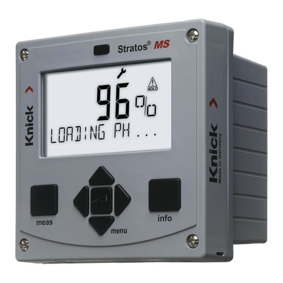
Stratos MS A405
Stratos Pro A2... pH
Conductivity Measurement
English
deutsch
Betriebsanleitung
Aktuelle Produktinformation:
www.knick.de
The Art of Measuring.
A2... PH
II 1G Ex ia IIC T3/T4/T6
14163 Berlin
14163 Berlin
SE 706X/1-NMSN
SE 706X/2-NMS
14163 Berlin
BVS 10 ATEX E0
BVS 10 ATEX E089 X
II 1G Ex ia IIC T
SE 706X/1-NM
II 1G Ex ia IIC T3/T4/T6
BVS 10 ATEX E
14163 Berlin
II 1G Ex ia IIC
SE 706X/2-NMSN
14163 Berlin
SE 706X/2-NM
BVS 10 ATEX E089 X
II 1G Ex ia IIC T3/T4/T6
BVS 10 ATEX E
II 1G Ex ia IIC
Advertisement
Table of Contents


Need help?
Do you have a question about the Stratos MS A405 Series and is the answer not in the manual?
Questions and answers