
Related Manuals for Knick Stratos Pro A201N-CC


Summary of Contents for Knick Stratos Pro A201N-CC
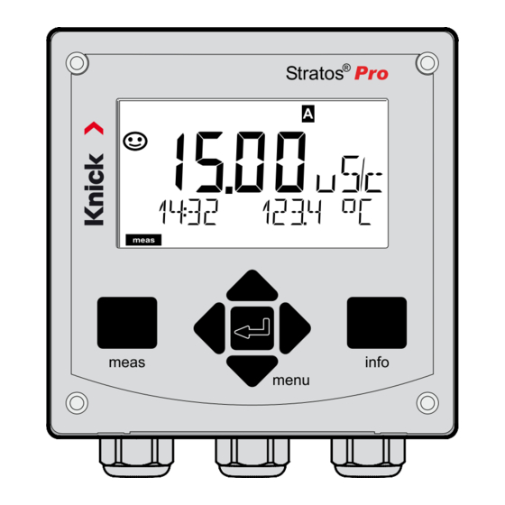
- Page 1 ® Stratos Pro A201N-CC User Manual Dual Conductivity Measurement Read before installation. Keep for future use. www.knick.de...
-
Page 2: Supplemental Directives
Supplemental Directives Read this document and retain it for future reference. Before assem- bling, installing, operating, or maintaining the product, ensure that you fully understand the instructions and risks. Observe all safety instructions. Failure to follow the instructions in this document may result in serious injury and/or property damage. -
Page 3: Documents Supplied
Safety Guide In official EU languages and others Quickstart Guides Installation and first steps: • Operation • Menu structure • Calibration • Error messages and recommended actions Test Report 2.2 According to EN 10204 Electronic Documentation www.knick-international.com: Manuals + software... -
Page 4: Table Of Contents
Documents Supplied ..............3 Safety ....................6 Always Read and Observe the Safety Instructions! ....6 Intended Use ..................6 Introduction ..................8 Overview of Stratos Pro A201N-CC ...........10 Assembly ..................11 Package Contents ................11 Electrical Installation ..............15 Rating Plates / Terminal Assignments ........16 Wiring of Stratos Pro A201N-CC ...........17... - Page 5 Table of Contents Configuration (Template for Copy) ...........42 Configuring Sensors A, B ..............44 Current Output 1 ................48 Current Output 2 ................56 (TAN SW-A005) .............58 CONTROL Input Alarm Settings ..................60 Time and Date ..................62 Measuring Point (TAG) ..............64 Display Backlighting .................64 Calibration ..................66 Calibration by Input of Cell Factor ..........67 Measurement ................68...
-
Page 6: Safety
This test should be carried out by the manufacturer at its factory. Intended Use Stratos Pro A201N-CC is a 2-wire device for two-channel measurement of electrical conductivity and temperature in liquids. The device has been designed for measurements before and after cation exchangers using commercial analog 2-electrode sensors. - Page 7 Safety Function Check Mode (HOLD Function) After activating configuration, calibration, or service, Stratos Pro enters function check mode (HOLD). The current outputs respond in accordance with the configuration. Operations must not be carried out while Stratos Pro is in function check (HOLD) mode, as the system may behave unexpectedly and put users at risk.
-
Page 8: Introduction
Introduction Housing and Mounting Options • The sturdy molded enclosure is designed for IP66/IP67 / TYPE 4X Outdoor protection, is made of PBT glass fiber reinforced PC, and has the following dimensions: H 148 mm, W 148 mm, T 117 mm. Knockouts in the housing enable • wall mounting (with sealing plugs to seal the housing) see page 12 •... - Page 9 Introduction Diagnostic Functions “Sensocheck” automatically monitors sensor and cables; and the “Sensoface“ function clearly indicates the sensor condition; see page 88. Data Logger The internal logbook (TAN SW-A002) can handle up to 100 entries – up to 200 with AuditTrail (TAN SW-A003); see page 72. Password Protection Password protection (passcodes) for granting access rights during operation can be configured;...
-
Page 10: Overview Of Stratos Pro A201N-Cc
Overview Overview of Stratos Pro A201N-CC Output 1 input Output 2 RS 485 Current input HOLD input CONTROL input... -
Page 11: Assembly
Assembly Package Contents Note: Check all components for damage upon receipt. Do not use damaged parts. The package should contain: • Front unit, rear unit, bag containing small parts • Specific test report • Documentation (see page 3) Fig.: Assembling the enclosure 1) Insertable jumper (3x) 6) Blanking plug (2x, non-Ex 2) Plate (1x), for conduit mount-... - Page 12 Assembly Mounting Plan, Dimensions 1) Cable gland (3 x) 2) Knockouts for cable gland or ½” conduit, 21.5 mm dia. (2 knockouts) Conduit couplings not included! 3) Knockout for pipe mounting (4 x) 4) Knockout for wall mounting (2 x) Fig.: Mounting plan (All dimensions in mm!)
- Page 13 Assembly Pipe Mounting, Protective Hood ø40...ø60 1) Hose clamp with worm gear drive to DIN 3017 (2 x) 2) Pipe-mount plate (1 x) 3) For vertical or horizontal posts or pipes 4) Self-tapping screw (4 x) Fig.: Pipe-mount kit, accessory ZU 0274 (All dimensions in mm!) Fig.: Protective hood for wall and pipe mounting, accessory ZU 0737 (All dimensions in mm!)
- Page 14 Assembly Panel Mounting < 30 1) Circumferential sealing (1 x) 2) Screws (4 x) 3) Position of control panel 4) Span piece (4 x) 5) Threaded sleeve (4 x) Cutout 138 x 138 mm (DIN 43700) 1...22 Fig.: Panel-mount kit, accessory ZU 0738 (All dimensions in mm!)
-
Page 15: Electrical Installation
Electrical Installation Before commencing with the installation, make sure that all lines to be connected are de-energized. Observe the safety instructions; see page 6. Cable Glands Cable glands 5 cable glands M20 x 1.5 A/F 24 mm Clamping ranges Standard sealing insert: 7 … 13 mm Reduction sealing insert: 4 …... -
Page 16: Rating Plates / Terminal Assignments
Installation Rating Plates / Terminal Assignments Fig.: Terminal assignments of Stratos Pro A201 Fig.: Stratos Pro A201N rating plate at outside bottom of front (illustrative example) -
Page 17: Wiring Of Stratos Pro A201N-Cc
Installation Wiring of Stratos Pro A201N-CC Sensor connection MK-CC module Areas for placing the screwdriver to pull out the terminals HART Terminal row 1 Terminal row 2 Fig.: MK-CC module terminal assignments In addition: 2 HART pins (between terminal row 1 and 2) -
Page 18: Wiring Examples
Wiring Examples Example 1: Measuring task: Dual conductivity, temperature Sensors (principle): 2 electrodes, coaxial... - Page 19 Wiring Examples Example 2: Measuring task: Dual conductivity, temperature Sensors: SE604, 2 electrodes...
- Page 20 Wiring Examples Example 3: Measuring task: Dual conductivity, temperature Sensors: SE610, 2 electrodes...
-
Page 21: User Interface, Keypad
User Interface, Keypad MEMO SENS 1 Display 2 Keypad 3 Rating plate (enclosure bottom) Function meas • Return to last menu level • Directly to measuring mode (press > 2 s) • Measuring mode: other display info • Retrieve information •... -
Page 22: Display
Display MEMO SENS 1 Temperature 13 Info available 2 Sensocheck 14 Hold mode active 3 Interval/response time 15 Main display 4 Sensor data 16 Secondary display 5 Not used 17 Proceed using enter 6 Limit message: 18 Not used Limit 1 or Limit 2 19 Diagnostics 7 Alarm... -
Page 23: Measuring Mode
Measuring Mode After the operating voltage has been connected and the sensor identi- fied, the analyzer automatically goes to “Measuring“ mode. To call the measuring mode from another operating mode (e.g. Diagnostics, Service): Hold meas key depressed (> 2 s). Display active Sensoface indicator measuring... -
Page 24: Selecting The Mode / Entering Values
Selecting the Mode / Entering Values To select the operating mode: 1) Hold meas key depressed (> 2 s) (directly to measuring mode) 2) Press menu key: the selection menu appears 3) Select operating mode using left / right arrow key 4) Press enter to confirm the selected mode Selection menu Selected mode... - Page 25 Display in Measuring Mode The MAIN DISPLAY is the display which is shown in measuring mode. To call the measuring mode from any other mode, hold the meas key depressed for at least 2 sec. meas key enter key By pressing meas briefly you can step through further displays such as tag number (TAG) or flow (L/h).
-
Page 26: Color-Coded User Interface
Color-Coded User Interface The color-coded user interface* guarantees increased operating safety. Operating modes are clearly signaled. The normal measuring mode is white. Information text appears on a green screen and the diagnostic menu appears on turquoise. The orange HOLD mode (e.g. during calibration) is quickly visible as is the magenta screen which indicates asset management messages for predictive diagnostics –... -
Page 27: Operating Modes
Operating Modes Diagnostics Display of calibration data, display of sensor data, performing a device self-test, viewing the logbook entries, display of hardware/software versions of the individual components. The logbook (TAN SW-A002) can store 100 events (00...99). They can be displayed directly on the device. - Page 28 Operating Modes / Functions TAG display CLK display Meas. mode (if configured) (main display after 60 s after 60 s selectable) Pressing the menu key (down arrow) opens the selection menu. Select the menu group using the left/right arrow keys. Pressing enter opens a menu item.
-
Page 29: Hold Mode
HOLD Mode The HOLD mode is a safety mode during configuration, calibration, and servicing. Output current is frozen (LAST) or set to a fixed value (FIX). The HOLD mode is indicated by orange display backlighting. HOLD mode, display icon: Output signal response •... -
Page 30: Alarm
Alarm External activation of HOLD (TAN SW-A005) The HOLD mode can be activated from outside by sending a signal to the Hold input (e.g. from the process control system). Power supply 12...24 V AC/DC HOLD input Stratos Pro A201 Process control system HOLD inactive 0...2 V AC/DC HOLD active... -
Page 31: Alarm And Hold Messages
Alarm and HOLD Messages Message Released by Cause Alarm Sensocheck Polarization / Cable (22 mA) Error messages Flow (CONTROL input) Alarm Flow (current input) contact ERR A / ERR B: conductance > 250,000 µS opens ERR A / ERR B: conductivity > 10,000 µS/cm HOLD HOLD HOLD via menu or input... -
Page 32: Configuration
Configuration CAUTION! Incorrect parameter settings or adjustments can result in incorrect outputs. Stratos Pro must therefore be commissioned by a system specialist, all its parameters must be set, and it must be fully adjusted. For detailed information on parameter setting and adjustment, see the user manual Menu Structure of Configuration The configuration steps are assigned to different menu groups. -
Page 33: Setup And Channel Selection On The Device
Setup and Channel Selection on the Device Sensors A and B – Arrangement Device type: Cond-Cond Inlet: Connection length COND A sensor max. 3 m with fitting Outlet: Cation exchanger COND B sensor with fitting Channel Selection and Display Assignment Display DISPLAY: OUT 1... -
Page 34: Calculations (Calc)
Calculations (CALC) Calculations (CALC) Calculation Formula Difference Ratio Passage Rejection Deviation pH value Additional specifications possible for acc. to VBG S-006 calculating the consumption of the ion exchanger (size, capacity, efficiency) Alkalizing agent NaOH Alkalizing agent LiOH Alkalizing agent ON / OFF Displaying the remaining capacity: Diagnostics / Monitor menu After replacement of the ion exchanger... - Page 35 Calculations (CALC) PARAMETER W, A, B specifiable -C9- ALKALISING Concentration of the alkalizing agent selecting NaOH, NH , LiOH nAOH Concentration calculation Concentration calculation LiOH Concentration calculation See p. 46 for configuration. *) Input of user-specific parameters possible **) With C6 and C9, the concentration of the alkalizing agent can be shown in the measurement display and in the sensor monitor and it can be switched to the current outputs.
-
Page 36: Calculating The Ph Value By Means Of Dual Conductivity Measurement
pH Value Calculation Calculating the pH Value by Means of Dual Conductivity Measurement When monitoring boiler feedwater in power plants, dual conductivity measurement can be used to calculate the pH value. For that purpose, the boiler feedwater conductance is measured before and after the cation exchanger. - Page 37 Configuration Configuration Choices Default (this setting applies to both channels, A and B) (Selected in text line) Alkalizing agent Entries for Calculating the Consumption of the Ion Exchanger...
- Page 38 Configuration Configuration Choices Default 1) The cell constant can be modified by an entry in the configuration menu or by cal- ibration (one storage position). This means, a cell constant determined by calibra- tion is taken over by pressing enter during configuration. It remains unchanged until a new value is entered.
- Page 39 Configuration Configuration Choices Default Output 1 (OUT1) Input range: selected CHANNEL Vertex X : BEGIN ≤ CORNER X ≤ END (rising) BEGIN ≥ CORNER X ≥ END (falling) Input range: selected CHANNEL Default: 12 mA Vertex Y: (0) 4 mA ≤ CORNER Y ≤ 20 mA Output 2 (OUT2) Selection as for OUT1...
- Page 40 Configuration Control input (CNTR_IN) 0 ... 20000 12000 pulses/liter pulses/liter Alarm (ALARM) These menu items appear only if selected. LIMIT I-IN can be used to measure and monitor the current input (e.g. flow). For monitoring, you can enter a setpoint at which an alarm message is released: "ERR 71 LIMIT I-INPUT“...
- Page 41 Configuration Configuration Choices Default Switching outputs (Rel1/Rel2) Real-time clock (CLOCK) CLK: FORMAT 24 h / 12 h 24 h TIME hh/mm 00..23:00...59 12 h TIME hh/mm 00 ... 12:59 AM / 01 ... 11:59 PM DAY/MONTH 01...31/01...12 YEAR 2000...2099 Measuring points (TAG) TAG: (Input in text line) A...Z, 0...9, –...
-
Page 42: Configuration (Template For Copy)
Configuration (Template for Copy) Parameter Setting S_A: Cell factor A S_A: Temperature compensation A S_B: Cell factor B S_B: Temperature compensation B MEAS: Measuring range MEAS: Temperature unit MEAS: Calculation MEAS: Coefficient C (for variable pH only, -C7-) MEAS: Factor F1 (for variable pH only, -C7-) MEAS: Factor F2 (for variable pH only, -C7-) MEAS: Factor F3 (for variable pH only, -C7-) MEAS: Parameter W (for USER SPEC only, -C8-) - Page 43 Configuration (Template for Copy) Parameter Setting OT2: Filter time OT2: FAIL 22 mA (error messages) OT2: FACE 22 mA (Sensoface messages) OT2: HOLD mode OT2: HOLD FIX current IN: Level or flow IN: (Flow meter) Adjusting pulses/liter ALA: Delay ALA: Sensocheck on/off ALA: Flow control FLOW CNTR on/off ALA: Minimum flow (hysteresis fixed at 5 %) ALA: Maximum flow (hysteresis fixed at 5 %)
-
Page 44: Configuring Sensors A, B
Configuration Configuring Sensors A, B Specifying cell factor, selecting temperature compensation 1) Press menu key. 2) Select CONF using keys, press enter. 3) Select SENSOR_A menu using keys, press enter. 4) All items of this menu group are indicated by the “S_A:”... - Page 45 Configuration Menu item Action Choices Sensor A Select SENSOR_A menu using keys, press enter. Enter cell factor Modify digit using keys, Sensor A select next digit using keys. Press enter to confirm. Temp compensation Select using keys. Press enter to confirm.
- Page 46 Configuration Measuring Range, Calculation of Output Parameters 1) Press menu key. 2) Select CONF using keys, press enter. 3) Select MEAS MODE menu using keys, press enter. 4) All items of this menu group are indicated by the “MES:” code. Press enter to select menu, edit using arrow keys (see next page).
- Page 47 Configuration Menu item Action Choices Range (resolution) Select using keys. Press enter to confirm. Temperature unit Select °C or °F using keys. Press enter to confirm. Calculation Select using keys. Press enter to confirm. Calculation type Select desired calculation type using ...
-
Page 48: Current Output 1
Configuration Current Output 1 Process variable. Current start. Current end. 1) Press menu key. 2) Select CONF using keys, press enter. 3) Select OUT1 menu using keys, press enter. 4) All items of this menu group are indicated by the “OT1:”... - Page 49 Configuration Menu item Action Choices Process variable Select using keys: Cond: Conductivity TMP: Temperature CALC: Calculation Press enter to confirm. Current start As selected for process Modify digit using variable/range keys, If the adjusted range is select next digit using exceeded, the device ...
- Page 50 Configuration Current Output 1 Output current curve 1) Press menu key. 2) Select CONF using keys, press enter. 3) Select OUT1 menu using keys, press enter. 4) All items of this menu group are indicated by the “OT1:” code. Press enter to select menu, edit using arrow keys (see next page).
- Page 51 Configuration Menu item Action Choices Output current Select using keys. Linear curve Press enter to confirm. curve biLIN Bilinear curve Current start Entered value applies to Enter value using selected process variable/ keys. and current end range If the adjusted range is exceeded, the device Press enter to confirm.
- Page 52 Configuration Current Output 1 Adjusting time interval of output filter 1) Press menu key. 2) Select CONF using keys, press enter. 3) Select OUT1 menu using keys, press enter. 4) All items of this menu group are indicated by the “OT1:”...
- Page 53 Configuration Menu item Action Choices Time averaging filter Enter value using keys. Press enter to confirm. Time averaging filter To smoothen the current output, a low-pass filter with adjustable filter time constant can be switched on. When there is a jump at the input (100 %), the output level is at 63 % after the time interval has been reached.
- Page 54 Configuration Current Output 1 Output current during Error and HOLD 1) Press menu key. 2) Select CONF using keys, press enter. 3) Select OUT1 menu using keys, press enter. 4) All items of this menu group are indicated by the “OT1:”...
- Page 55 Configuration Menu item Action Choices Output current during Select ON (22 mA for error message) or OFF using error message keys. Press enter to confirm. Output current during Select ON or OFF using ON/OFF keys. Sensoface messages Confirm by pressing enter OT1: FACE 22 mA Output current during LAST: During HOLD the...
-
Page 56: Current Output 2
Configuration Current Output 2 Output current range. Process variable. 1) Press menu key. 2) Select CONF using keys, press enter. 3) Select OUT2 menu using keys, press enter. 4) All items of this menu group are indicated by the “OT2:”... - Page 57 Configuration Menu item Action Choices Process variable Select using keys: Cond: Conductivity TMP: Temperature Press enter to confirm. All the following adjustments are made as for current output 1 (see there)!
-
Page 58: Control Input (Tan Sw-A005)
Configuration (TAN SW-A005) CONTROL Input Flow measurement 1) Press menu key. 2) Select CONF using keys, press enter. 3) Select CNTR_IN menu using keys, press enter. 4) All items of this menu group are indicated by the “IN:” code. Press enter to select menu, edit using arrow keys (see next page). - Page 59 Configuration Menu item Action Choices Select function of Level Select using keys. Flow (for connecting a Press enter to confirm. CONTROL input pulse-output flow meter) Adjust to flow meter With “Flow” selected, 12000 pulses/liter you must adjust the device to the flow meter used.
-
Page 60: Alarm Settings
Configuration Alarm Settings Delay. Sensocheck. 1) Press menu key. 2) Select CONF using keys, press enter. 3) Select ALARM menu using keys, press enter. 4) All items of this menu group are indicated by the “ALA:” code. Press enter to select menu, edit using arrow keys (see next page). - Page 61 Configuration Menu item Action Choices Delay Enter value using keys. Press enter to confirm. Sensocheck Select Sensocheck (con- tinuous monitoring of sensor). Select ON or OFF using keys. Press enter to confirm. CONTROL input The CONTROL input can generate an alarm depending on its assign- ment in the CONF menu:...
-
Page 62: Time And Date
Configuration Time and Date 1) Press menu key. 2) Select CONF using , press enter. 3) Select CLOCK using keys, press enter. 4) All items of this menu group are indicated by the “CLK:” code. Press enter to select menu, edit using arrow keys (see next page). - Page 63 Configuration Time and Date Control of the calibration and cleaning cycles is based on the time and date of the integrated real-time clock. In measuring mode the time is shown in the lower display. When using digital sensors, the calibration data is written in the sensor head. In addition, the logbook entries (cf Diagnostics) are provided with a time stamp.
-
Page 64: Measuring Point (Tag)
Configuration Measuring Point (TAG) Display Backlighting 1) Press menu key. 2) Select CONF using , press enter. 3) Select TAG or DISPLAY using keys, press enter. 4) All items of this menu group are indicated by the “TAG:” or “DSP” code. Press enter to select menu, edit using arrow keys (see next page). - Page 65 Configuration Menu item Action Choices Measuring point In the lower display line you can A...Z, 0...9, – + enter a designation for the measuring < > ? / @ (TAG) point (TAG) and for a group of mea- suring points (GROUP) if applicable. Up to 32 digits are possible.
-
Page 66: Calibration
Calibration Note: • All calibration procedures must be performed by trained person- nel. Incorrectly set parameters may go unnoticed, but change the measuring properties. Each sensor is calibrated separately by entering the cell factor. -
Page 67: Calibration By Input Of Cell Factor
Calibration by Input of Cell Factor You can directly enter the value for the cell factor of a sensor. This value must be known, i.e., determined beforehand in the laboratory, for example. The selected process variable and the temperature are displayed. -
Page 68: Measurement
Measurement Display Remark From the configuration or calibration menus, you can switch the device to measuring mode by pressing the meas key (> 2 sec). In the measuring mode the upper display line shows the configured process variable, the lower display line shows the time and the second configured process variable. -
Page 69: Diagnostics
Diagnostics (DIAG) Diagnostics In the Diagnostics mode you can access the following menus without interrupting the measurement: Viewing the calibration data Starting a device self-test Viewing the logbook entries Displaying currently measured values, incl. remaining capacity of the ion exchanger (if provided) Displaying device type, software version, serial number Access to diagnostics can be protected with a passcode (SERVICE menu). - Page 70 Diagnostics Menu item Remark Display of calibration data Select CALDATA using, press enter to confirm. Use thekeys to select the desired parameter from the bottom line of the display (LAST CAL CELL_A CELL_B). The selected parameter is shown in the main display. Press meas to return to measurement.
- Page 71 Diagnostics Display Menu item Device self-test (To abort, you can press meas.) 1) Display test: Display of all segments with changing background colors white/green/red. Proceed by pressing enter. 2) RAM test: Hourglass blinks, then display of --PASS-- or --FAIL-- Proceed by pressing enter. 3) EEPROM test: Hourglass blinks, then display of --PASS-- or --FAIL-- Proceed by pressing enter.
- Page 72 Diagnostics Menu item Remark Display of logbook entries Select LOGBOOK using, press enter to confirm. Using the keys, you can scroll backwards and forwards through the logbook (entries -00-...-99-), -00- being the last entry. If the display is set to date/time, you can search for a particular date using the ...
- Page 73 Diagnostics Display Remark Remaining capacity When calculating the consumption of the ion exchanger has been activated in the configuration, of the ion exchanger the sensor monitor shows the remaining capacity of the ion exchanger. Press meas to return to measurement. Version Here, you find the data you require for requesting a device-specific option.
-
Page 74: Service
Service In the Service mode you can access the following menus: MONITOR Displaying currently measured values SENSOR Resetting TTM (ISM only ), incrementing the autoclaving counter OUT1 Testing current output 1 OUT2 Testing current output 2 CODES Assigning and editing passcodes DEFAULT Resetting the device to factory settings OPTION... - Page 75 Service Menu item Remark Displaying currently measured values (sensor monitor) with HOLD mode activated: Select MONITOR using, press enter to confirm. Select variable in the bottom text line using. The selected parameter is shown in the upper display line. As the device is in HOLD mode, you can perform Display example: validations using simulators without influencing the signal outputs.
- Page 76 Service Menu item Remark Assigning passcodes: In the “SERVICE - CODES“ menu you can assign pass- codes to DIAG, HOLD, CAL, CONF and SERVICE modes (Service preset to 5555). When you have lost the Service passcode, you have to request an “Ambulance TAN“ from the manufac- turer specifying the serial number of your device.
-
Page 77: Operating States
Operating states Operating States Operating status Measuring Diag 60 s CAL_CELL_A Cell factor CAL_CELL_B Cell factor HOLD input CONF 20 min SERVICE 20 min Explanation: as configured (Last/Fix) active... -
Page 78: Supply Units And Connection
Supply Units and Connection Recommended Power Supply Units: Order No.: Repeater power supply, non-Ex, 24 V DC, IsoAmp PWR B 10116 output 4...20 mA Repeater power supply, non-Ex, 24 V DC, IsoAmp PWR A 20100 HART, output 0/4...20 mA / 0...10 V Connection to Supply Units Supply unit 1 Supply unit 2... -
Page 79: Product Line And Accessories
Product Line and Accessories Order Code Stratos Pro A201 Example 2-wire / 4-20 mA B,C,E Communication Without (HART retrofittable via TAN) 0 Version number Version Approvals General Safety ATEX / IECEx Zone 2 ATEX / IECEx / FM / CSA Zone 1 / Cl 1 Div 1 Measuring channel Memosens pH / Redox digital... -
Page 80: Specifications
Specifications COND inputs A/B 2 inputs for 2-electrode sensors Measuring range 2-el. sensors 0 … 30,000 µS · c Display ranges Conductivity 0.000 ... 9.999 µS/cm 00.00 ... 99.99 µS/cm 000.0 ... 999.9 µS/cm 0000 ... 9999 µS/cm Resistivity 00.00 … 99.99 MΩ · cm Response time (T90) Approx. - Page 81 Specifications Sensor monitor Direct display of measured values from sensor for validation resistance / conductance / temperature Temperature input A/B Pt1000, 2-wire connection Measuring range -50 ... +200 °C / –58 ... +392 °F Resolution 0.1 °C / 0.1 °F Measurement error 1,2,3) 0.5 K (1 K >...
- Page 82 Specifications Output 2 Current loop 4 ... 20 mA, floating, protected against inverse polarity Supply voltage 14 ... 30 V Process variable * Conductivity A/B, resistivity A/B, temperature A/B, or CALC Characteristic linear, bilinear Overrange * 22 mA in the case of error messages Output filter * filter, time constant 0 ...
- Page 83 Specifications Data retention Parameters, calibration data, logbook > 10 years (EEPROM) Housing Molded enclosure, glass fiber reinforced Front unit material: PBT Rear unit material: PC Mounting Wall, pipe/post or panel mounting Color Gray RAL 7001 Ingress protection IP66/IP67/TYPE 4X outdoor (with pressure compensation) when the device is closed Flammability UL 94 V-0 for external parts...
-
Page 84: Error Handling
Error Handling Alarm condition: • The display backlighting turns red • The alarm icon is displayed • The complete measured-value display blinks • “ERR xxx“ is displayed in the lower menu line Press the [info] key to view a short error text: •... -
Page 85: Error Messages
Error Messages Info text Problem Error (is displayed in case of fault Possible causes when the Info key is pressed) ERR 10 CONDUCTANCE TOO HIGH Conductance value out of range: > 250 mS (Channel A) ERR 40 (Channel B) ERR 11 Display range violation CONDUCTIVITY RANGE Cond >... - Page 86 Error Messages Info text Problem Error (is displayed in case of fault Possible causes when the Info key is pressed) ERR 74 CATION EXCHANGER INVALID Flow too low or no flow: CALCULATION Flow ≤ 4.00 l/h; calculated pH value: < 7.5 or > 10.5; conductivity values: B ≥...
-
Page 87: Decommissioning
Decommissioning Disposal Local codes and regulations must be observed when disposing of the product. Returns If required, send the product in a clean condition and securely packed to your local contact. See www.knick.de. -
Page 88: Sensocheck And Sensoface
Sensocheck and Sensoface (Sensocheck must have been activated during configuration.) The smiley in the display (Sensoface) alerts to sensor problems (defective sensor, defective cable, maintenance required). The permisible calibration ranges and the conditions for a friendly, neutral, or sad Sensoface are summarized in the following table. Additional icons refer to the error cause. - Page 89 Sensoface Display Problem Status Sensor defect Wrong or defective sensor, sig- nificant polarization of sensor or excessive cable capacitance (see also error message Err 15). Temperature Temperature outside measuring ranges Cell factor Cell factor < 0.005 cm channel A, B cell factor >...
-
Page 90: Hart: Typical Applications
HART: Typical Applications (SW-A001) HART Terminal + out Power supply 250 Ω 4 ... 20mA min 19 V - out 1 - out 2 A201 HART Terminal HART Terminal Repeater + out power supply 4 ... 20mA - out 1 - out 2 A201... -
Page 91: Fda 21 Cfr Part 11
FDA 21 CFR Part 11 Conformity with FDA 21 CFR Part 11 In their directive “Title 21 Code of Federal Regulations, 21 CFR Part 11, Electronic Records; Electronic Signatures“ the American health agency FDA (Food and Drug Administration) regulates the production and processing of electronic documents for pharmaceutical develop- ment and production. -
Page 92: Index
Index Access code assignment 76 Accessories 79 Activating an option 76 Adjustable ranges, current outputs 41 Adjustable ranges, relay contacts 41 Alarm 30 Alarm and HOLD messages 31 Alarm settings 60 Ambulance TAN 76 Assembly 11 Audit Trail 91 Audit Trail, diagnostics 72 Autorange 49 Backlighting 22 Bilinear curve 51... - Page 93 Index Configuration, sensor 44 Configuration, time and date 62 Connection length for sensors, maximum (CC) 33 Connection to supply units 78 Consumption calculation of ion exchanger 34 Consumption calculation, reset 75 CONTROL, alarm settings 61 CONTROL, configuring the input 58 CONTROL input 31 Control inputs 9 Current input 31...
- Page 94 Index EEPROM test 71 Electrical installation 15 Electronic Signature 91 Enabling an option 76 Enclosure 12 Enclosure components 11 Entering values 24 Error handling 84 Error messages 85 Extended logbook, Audit Trail 91 Extended logbook, diagnostics 72 FDA 21 CFR Part 11 91 FLASH test 71 FLOW 59 Flow measurement 58...
- Page 95 Index Measurement, general 23 Measuring mode 68 Measuring point, arrangement (CC) 33 Measuring point (TAG) 65 Measuring range, configuration 46 Menu structure of configuration 32 Message via CONTROL input 31 Message via current input 31 Module test 71 Monitoring function of ion exchanger 41 Mounting options 8 Mounting plan 12 Operating modes 27...
- Page 96 Index RAM test 71 Rated operating conditions 83 Rating plates 16 Remaining capacity of ion exchanger 73 Reset to factory settings 76 Returns 87 Safety 6 Safety guide 3 Selection menu 24 Sensocheck, configuration 61 Sensocheck, description 88 Sensoface, description 88 Sensoface, troubleshooting 84 Sensor connection 17 Sensor monitor, diagnostics 72...
- Page 97 Index TAN input 76 TAN options, activation 76 TAN options, overview 79 Technical data 80 Terminal assignments 16 Test report 2.2 3 Time and date (configuration) 62 Time and date (usage) 63 Time averaging filter 53 Time, display 68 Transaction number (TAN) 76 User interface 21 Weather protector 13 Wiring 17...
- Page 98 Knick Elektronische Messgeräte GmbH & Co. KG Headquarters Beuckestraße 22 • 14163 Berlin Germany Phone: +49 30 80191-0 Fax: +49 30 80191-200 info@knick.de www.knick.de Local Contacts www.knick-international.com Translation of the original instructions Copyright 2022 • Subject to change Version: 4 • This document was published on August 17, 2022.
Need help?
Do you have a question about the Stratos Pro A201N-CC and is the answer not in the manual?
Questions and answers