
Related Manuals for Knick Stratos Pro A201N-COND-0


Summary of Contents for Knick Stratos Pro A201N-COND-0
- Page 1 ® Stratos Pro A201COND Conductivity Measurement User Manual with 2-/4-Electrode Sensors Read before installation. Keep for future use. www.knick.de...
-
Page 2: Supplemental Directives
Supplemental Directives Read this document and retain it for future reference. Before assem- bling, installing, operating, or maintaining the product, ensure that you fully understand the instructions and risks. Observe all safety instructions. Failure to follow the instructions in this document may result in serious injury and/or property damage. -
Page 3: Documents Supplied
Quickstart Guides Installation and first steps: • Operation • Menu structure • Calibration • Error messages and recommended actions Test Report 2.2 According to EN 10204 Electronic Documentation www.knick-international.com: Manuals + software Ex devices: Control Drawings EU Declaration of Conformity... -
Page 4: Table Of Contents
Table of Contents Supplemental Directives ................ 2 Documents Supplied ................3 Safety ......................7 Intended Use ....................7 Introduction ..................... 9 Overview of Stratos Pro A201COND ..........12 Assembly ....................13 Package Contents ..................13 Mounting Plan, Dimensions ..............14 Pipe Mounting, Protective Hood ............15 Panel Mounting .....................16 Electrical Installation ................ - Page 5 Table of Contents Configuration ..................40 Menu Structure of Configuration ............40 Parameter Set Selection ................42 Configuration (Template for Copy) ............48 Sensor .......................50 Sensor Verification (TAG, GROUP) ............58 Current Output 1 ..................60 Current Output 2 ..................70 Temperature Compensation ..............72 CONTROL Input (TAN SW-A005) .............76 Alarm Settings ....................78 Time and Date ....................82 Measuring Points (TAG/GROUP) ............84...
- Page 6 Table of Contents Maintenance and Repair ..............110 A201B/X: Supply Units and Connection .........111 Product Line and Accessories ............112 Specifications ..................113 Calibration Solutions ................119 Concentration Measurement ............121 Concentration Curves ................122 Error Handling ..................127 Error Messages ..................128 Decommissioning ................131 Disposal ......................131 Returns ......................
-
Page 7: Safety
Safety Always Read and Observe the Safety Instructions! The device is constructed in accordance with the latest technology and generally accepted safety rules and regulations. Under certain circumstances, however, usage may pose risks to users or cause damage to the device. Commissioning must be carried out by specialist personnel authorized by the operating company. - Page 8 Safety Function Check Mode (HOLD Function) After activating configuration, calibration, or service, Stratos Pro enters function check mode (HOLD). The current outputs respond in accordance with the configuration. Operations must not be carried out while Stratos Pro is in function check (HOLD) mode, as the system may behave unexpectedly and put users at risk.
-
Page 9: Introduction
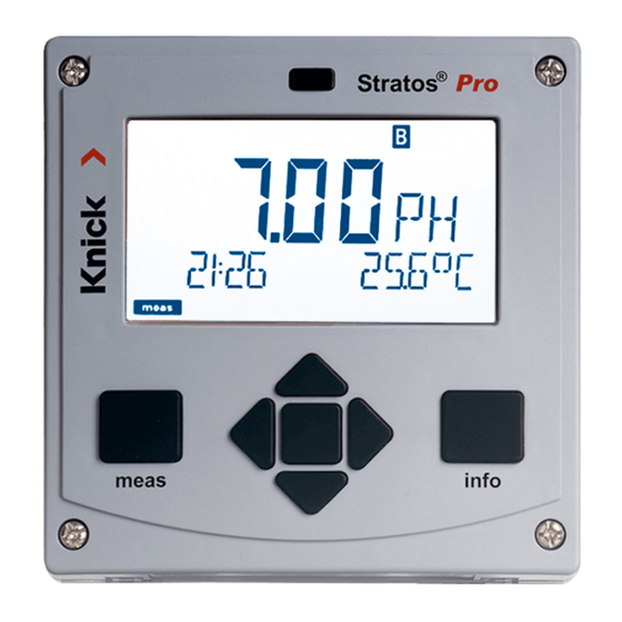
Introduction Housing and Mounting Options • The sturdy molded enclosure is designed for IP66/IP67 / TYPE 4X Outdoor protection, is made of PBT glass fiber reinforced PC, and has the following dimensions: H 148 mm, W 148 mm, T 117 mm. Knockouts in the housing enable • wall mounting (with sealing plugs to seal the housing) see page 14 •... - Page 10 Introduction Display Plain‑text messages on a large, backlit LC display enable intuitive op‑ eration. You can specify which values are to be displayed in standard measuring mode (“Main Display, ” see page 33). Color-Coded User Interface The colored display backlighting indicates different operating states (e.g., alarm: red, HOLD mode: orange;...
- Page 11 Introduction Control Inputs (TAN SW-A005) I input Current The analog (0) 4 ... 20 mA current input can be used for external temperature compen‑ input sation; see page 72. HOLD HOLD (Floating digital control input) The HOLD input can be used for external input activation of HOLD mode;...
-
Page 12: Overview Of Stratos Pro A201Cond
Overview Overview of Stratos Pro A201COND COND I hi Output 1 input U hi U lo Output 2 I lo RTD (GND) RTD (Sense) Shield RS-485 Current Input + Input – input HOLD HOLD + HOLD – input CONTROL CONTROL + CONTROL –... -
Page 13: Assembly
Assembly Package Contents Note: Check all components for damage upon receipt. Do not use damaged parts. The package should contain: • Front unit, rear unit, bag containing small parts • Specific test report • Documentation (see page 3) Fig.: Assembling the enclosure 1) Insertable jumper (3x) 6) Blanking plug (2x, non-Ex 2) Plate (1x), for conduit mount-... -
Page 14: Mounting Plan, Dimensions
Assembly Mounting Plan, Dimensions 1) Cable gland (3 x) 2) Knockouts for cable gland or ½” conduit, 21.5 mm dia. (2 knockouts) Conduit couplings not included! 3) Knockout for pipe mounting (4 x) 4) Knockout for wall mounting (2 x) Fig.: Mounting plan (All dimensions in mm!) -
Page 15: Pipe Mounting, Protective Hood
Assembly Pipe Mounting, Protective Hood ø40...ø60 1) Hose clamp with worm gear drive to DIN 3017 (2 x) 2) Pipe-mount plate (1 x) 3) For vertical or horizontal posts or pipes 4) Self-tapping screw (4 x) Fig.: Pipe-mount kit, accessory ZU 0274 (All dimensions in mm!) Fig.: Protective hood for wall and pipe mounting, accessory ZU 0737 (All dimensions in mm!) -
Page 16: Panel Mounting
Assembly Panel Mounting < 30 1) Circumferential sealing (1 x) 2) Screws (4 x) 3) Position of control panel 4) Span piece (4 x) 5) Threaded sleeve (4 x) Cutout 138 x 138 mm (DIN 43700) 1...22 Fig.: Panel-mount kit, accessory ZU 0738 (All dimensions in mm!) -
Page 17: Electrical Installation
Electrical Installation Before commencing with the installation, make sure that all lines to be connected are de-energized. Observe the safety instructions; see page 7. Cable Glands In a hazardous location, only cable glands with suitable approvals may be used. The installation instructions of the manufacturer must be observed. -
Page 18: Rating Plates / Terminal Assignments
Electrical Installation Rating Plates / Terminal Assignments Fig.: Terminal assignments of Stratos Pro A201 Fig.: Stratos Pro A201N rating plate at outside bottom of front (illustrative example) -
Page 19: Wiring Of Stratos Pro A201Cond
Electrical Installation Wiring of Stratos Pro A201COND Sensor connection MK-COND module Areas for placing the screwdriver to pull out the terminals HART Fig.: MK-COND module Terminal row 1 Terminal row 2 terminal assignments Note: When a Memosens sensor is to be con- nected to the RS-485 interface (terminals 1...4), you must remove... -
Page 20: Wiring Examples
Wiring Examples Example 1: Measuring task: Conductivity, temperature Sensors (principle): 4 electrodes Place jumper across F and G when a 2-wire temperature probe is used! - Page 21 Wiring Examples Example 2: Measuring task: Conductivity, temperature Sensors (principle): 2 electrodes, coaxial Jumper! Jumper! Jumper!
- Page 22 Wiring Examples Example 3: Measuring task: Conductivity, temperature Sensors (example): SE604 Cable: ZU0645 Sensor head connector...
- Page 23 Wiring Examples Example 4: Measuring task: Conductivity, temperature Sensors (example): SE610...
- Page 24 Wiring Examples Example 5: Measuring task: Conductivity, temperature Sensors (example): SE620 VP cable: e.g, CA/VP6ST-003A...
- Page 25 Wiring Examples Example 6: Measuring task: Conductivity, temperature Sensors (example): SE630 Connection via GDM connector Sensor head connector...
- Page 26 Wiring Examples Example 7: Measuring task: Conductivity, temperature Sensors (example): SE600 / SE603 4-electrode fringe-field sensor *) Do not connect...
- Page 27 Wiring Examples Example 8: Measuring task: Conductivity, temperature Sensor: Memosens The Memosens sensor is connected to the RS-485 interface of the device – for an A2... Series (2-wire) device, the measuring module slot must be empty. Therefore, first remove the measuring module from the slot (see next page).
-
Page 28: Connecting A Memosens Sensor
Connecting a Memosens Sensor NOTICE! The slot for the MK-COND module must be empty – be sure to remove the module! Areas for placing the screwdriver to pull out the terminals HART Connection of Memosens: Wire color Brown Green Yellow White, transparent shield... -
Page 29: User Interface, Keypad
User Interface, Keypad MEMO SENS 1 Display 2 Keypad 3 Nameplate (enclosure bottom) Function • Return to last menu level • Directly to measuring mode (press > 2 s) • Measuring mode: other display • Retrieve information • Show error messages •... -
Page 30: Display
Display MEMO SENS 1 Temperature 13 Info available 2 Sensocheck 14 Hold mode active 3 Interval/response time 15 Main display 4 Sensor data 16 Secondary display 5 Not used 17 Proceed using enter 6 Limit message: 18 Not used Limit 1 or Limit 2 19 Diagnostics 7 Alarm... -
Page 31: Measuring Mode
Measuring Mode After the operating voltage has been connected, the analyzer auto- matically goes to “Measuring“ mode. To call the measuring mode from another operating mode (e.g., Diagnostics, Service): Hold meas key depressed (> 2 s). Sensoface indicator Active (sensor status) parameter set (configuration) Time... -
Page 32: Selecting The Mode / Entering Values
Selecting the Mode / Entering Values To select the operating mode: 1) Hold meas key depressed (> 2 s) (directly to measuring mode) 2) Press menu key: the selection menu appears 3) Select operating mode using left / right arrow key 4) Press enter to confirm the selected mode Selection menu Selected mode... -
Page 33: Display In Measuring Mode
Display in Measuring Mode The MAIN DISPLAY is the display which is shown in measuring mode. To call the measuring mode from any other mode, hold the meas key depressed for at least 2 sec. meas key enter key meas By pressing meas briefly you can step through further displays such as tag number (TAG) or flow (L/h). -
Page 34: Color-Coded User Interface
Color-Coded User Interface The color-coded user interface* guarantees increased operating safety. Operating modes are clearly signaled. The normal measuring mode is white. Information text appears on a green screen and the diagnostic menu appears on turquoise. The orange HOLD mode (e.g. during calibration) is quickly visible as is the magenta screen which indicates asset management messages for predictive diagnostics –... -
Page 35: Operating Modes
Operating Modes Diagnostics Display of calibration data, display of sensor data, performing a device self-test, viewing the logbook entries, display of hardware/software versions of the individual components. The logbook (TAN SW-A002) can store 100 events (00...99). They can be displayed directly on the device. -
Page 36: Menu Structure Of Modes And Functions
Menu Structure of Modes and Functions meas meas Meas. mode TAG display CLK display (main display selectable) after 60 s after 60 s Pressing the menu key (down arrow) opens the selection menu. Select the menu group using the left/right arrow keys. Pressing enter opens a menu item. -
Page 37: Hold Mode
HOLD Mode The HOLD mode is a safety state during configuration and calibration. Output current is frozen (LAST) or set to a fixed value (FIX). The HOLD mode is indicated by orange display backlighting. HOLD mode, display icon: Output signal response •... -
Page 38: Alarm
Alarm External activation of HOLD (SW-A005) The HOLD mode can be activated from outside by sending a signal to the HOLD input (e.g. from the process control system). Power supply HOLD 12...24 V AC/DC input Stratos Pro A201 Process control system HOLD inactive 0...2 V AC/DC HOLD active... -
Page 39: Alarm And Hold Messages
Alarm and HOLD Messages Message Released by Cause Alarm Sensocheck Polarization / Cable (22 mA) Error messages Flow (CONTROL input) ERR 10: Conductance > 3500 mS HOLD via menu or input Configuration Calibration Service Generating a message via the CONTROL input (TAN SW-A005) (min. -
Page 40: Configuration
Configuration CAUTION! Incorrect parameter settings or adjustments can result in incorrect outputs. Stratos Pro must therefore be commissioned by a system specialist, all its parameters must be set, and it must be fully adjusted. For detailed information on parameter setting and adjustment, see the user manual Menu Structure of Configuration The device provides 2 parameter sets “A“... - Page 41 Configuration Parameter Set A/B: Configurable Menu Groups Menu group Parameter set A Parameter set B Sensor selection Current output 1 Current output 1 Current output 2 Current output 2 Compensation Compensation Control input Alarm mode Alarm mode Parameter set selection Setting the clock TAG of measuring point TAG of measuring point...
-
Page 42: Parameter Set Selection
Configuration Parameter Set Selection Note: Manual selection of parameter sets must have been preset in the CONFIG > PARSET menu. Default setting is a fixed parameter set A. Wrong settings change the measurement properties! Manual switchover of parameter sets A/B Display Action To switch between parameter sets:... - Page 43 Configuration Configuration Configuration Choices Default SENSOR SNS: 2‑ELECTRODE 2‑ELECTRODE 4‑ELECTRODE MEMOSENS 2‑EL / 4‑EL CELLFACTOR 00.0000 ‑ 01.0000 c 19.9999 c MEAS MODE Cond Cond Conc % Sal ‰ USP μS/cm Cond MEAS RANGE x.xxx μS/cm xxx.x mS/cm xx.xx μS/cm xxx.x μS/cm xxxx μS/cm x.xxx mS/cm...
- Page 44 Configuration Configuration Configuration Choices Default SENSOR SNS: TEMP UNIT °C / °F °C TEMPERATURE AUTO, MAN, EXT AUTO (EXT. only with TAN option SW‑A005) AUTO RTD TYPE 100 PT 1000 PT 1000 PT 8.55 NTC 30 NTC Ni100 TEMPERATURE –50 ... 250 °C 025.0 °C (–58 ...
- Page 45 Configuration Configuration Choices Default Output 1 (OUT1) OT1: CHANNEL Cond/TMP Cond OUTPUT LIN / BiLIN / LOG BEGIN 4 mA xxxx 000.0 mS/cm END 20 mA xxxx 100.0 mS/cm BiLIN BEGIN 4 mA xxxx 000.0 mS/cm END 20 mA xxxx 100.0 mS/cm CORNER X Input range: selected CHANNEL...
- Page 46 Configuration Configuration Choices Default Temperature compensation (CORRECTION) TC SELECT LIN, NLF, NaCl HCl, NH3, NaOH TC LIQUID 00.00 ...19.99%/K 00.00%/K REF TEMP 000.0 ... 199.9 °C 025.0 °C TEMP EXT * ON/OFF I‑INPUT 0–20 mA / 4–20 mA 4–20 mA °C BEGIN 4 mA –50...250 °C 000.0 °C...
- Page 47 Configuration Configuration Choices Default Alarm (ALARM) ALA: DELAYTIME 0...600 SEC 0010 SEC SENSOCHECK ON/OFF TEMP CHECK ON/OFF FLOW CNTR ON/OFF FLOW MIN 0 ... 99.9 L/h 005.0 L/h FLOW MAX 0 ... 99.9 L/h 025.0 L/h Parameter set (PARSET) Select fixed parameter set PARSET FIX / PARSET FIX (A) or switch between A/B...
-
Page 48: Configuration (Template For Copy)
Configuration (Template for Copy) Parameter Parameter set A Parameter set B SNS: Sensor type SNS: Cell constant SNS: Measuring mode SNS: Measuring range SNS: Concentration determination SNS: Temperature unit SNS: Temp detection SNS: Manual temp SNS: RTD type SNS: CIP counter SNS: SIP counter SNS: CHECK TAG SNS: CHECK GROUP... - Page 49 Configuration (Template for Copy) Parameter Set A Set B OT2: Process variable OT2: Lin/bilin/log output OT2: Current start OT2: Current end OT2: Vertex X (bilinear curve only) OT2: Vertex Y (bilinear curve only) OT2: Filter time OT2: FAIL 22 mA (error messages) OT2: FACE 22 mA (Sensoface messages) OT2: HOLD mode OT2: HOLD FIX current...
-
Page 50: Sensor
Configuration Configuration Sensor Selecting the parameters 1) Press menu key. 2) Select CONF using , press enter. 3) Select parameter set using keys, press enter. 4) Select SENSOR menu using keys, press enter. 5) All items of this menu group are indicated by the “SNS:” code. - Page 51 Configuration Menu item Action Choices Select sensor type 2-ELECTRODE Select sensor type using keys. 4‑ELECTRODE MEMOSENS Press enter to confirm. Enter cell constant 00.0000...19.9999 c Modify digit using (01.0000 c) keys, select next digit using keys. Press enter to confirm. Select meas.
- Page 52 Configuration Sensor Selection: Concentration Determination 1) Press menu key. 2) Select CONF using keys, press enter. 3) Select parameter set using , press enter. 4) Select SENSOR menu using keys, press enter. 5) All items of this menu group are indicated by the “SNS:”...
- Page 53 Configuration Menu item Action Selection Concentration For concntration -01- (NaCl), ‑02‑ (HCl), measurement only ‑03‑ (NaOH), ‑04‑ (H determination ‑05‑ (HNO ), ‑06‑ (H Use the arrow keys ‑07‑ (HCl), ‑08‑ (HNO to select the desired ‑09‑ (H ), ‑10‑ (NaOH), concentration solution.
- Page 54 Configuration Sensor Select: Temperature unit, temperature detection, type of temp probe 1) Press menu key. 2) Select CONF using keys, press enter. 3) Select parameter set using , press enter. 4) Select SENSOR menu using keys, press enter. 5) All items of this menu group are indicated by the “SNS:”...
- Page 55 Configuration Menu item Action Choices Temperature unit Select °C or °F using keys. Press enter to confirm. Temperature Select mode using : AUTO: Measured by detection sensor MAN: Direct input of temperature, no measure‑ ment (see next step) EXT: Temperature speci‑ fied via current input (only if TAN E enabled) Press enter to confirm.
- Page 56 Configuration Sensor Adjust: Cleaning cycles, sterilization cycles 1) Press menu key. 2) Select CONF using keys, press enter. 3) Select parameter set using , press enter. 4) Select SENSOR menu using keys, press enter. 5) All items of this menu group are indicated by the “SNS:”...
- Page 57 Configuration Menu item Action Choices CIP / SIP Cleaning cycles Select ON or OFF using ON/OFF keys. Activates/deactivates log‑ ging in extended logbook (TAN SW‑A003). Press enter to confirm. Sterilization cycles Select ON or OFF using ON/OFF keys. Activates/deactivates log‑...
-
Page 58: Sensor Verification (Tag, Group)
Configuration Memosens Sensor Sensor Verification (TAG, GROUP) 1) Press menu key. 2) Select CONF using , press enter. 3) Select parameter set using keys, press enter. 4) Select SENSOR menu using keys, press enter. 5) All items of this menu group are indicated by the “SNS:” code. - Page 59 Configuration Menu item Action Choices Select ON or OFF using ON/OFF keys. Press enter to confirm. When switched on, the entry for “TAG” in the Memosens sensor is com‑ pared to the entry in the analyzer. If the entries differ, a mes‑ sage will be generated.
-
Page 60: Current Output 1
Configuration Current Output 1 Output current range. Process variable. 1) Press menu key. 2) Select CONF using keys, press enter. 3) Select parameter set using , press enter. 4) Select OUT1 menu using keys, press enter. 5) All items of this menu group are indicated by the “OT1:”... - Page 61 Configuration Menu item Action Choices Process variable Select using keys: Cond: Conductivity TMP: Temperature Press enter to confirm. Then select characteristic (LIN/biLIN/LOG). Current start Entered value applies to Modify digit using selected process variable/ keys, range select next digit using If the adjusted range is ...
- Page 62 Configuration Current Output 1 Output current curve, bilinear 1) Press menu key. 2) Select CONF using keys, press enter. 3) Select parameter set using , press enter. 4) Select OUT1 menu using keys, press enter. 5) All items of this menu group are indicated by the “OT1:”...
- Page 63 Configuration Menu item Action Choices Output current Select using keys. Linear characteristic Press enter to confirm. curve biLIN Bilinear curve Logarithmic curve Current start Entered value applies to Enter value using selected process variable/ keys. and current end range If the adjusted range is exceeded, the device...
- Page 64 Logarithmic Curve Nonlinear output current characteristic: allows measurements over several decades, e.g. measuring very low values with a high resolution and high values with a low resolution. Parameters required: Start and end value Possible start and end values The start value must be at least one decade lower than the end value. Start value and end value must be specified in the same units (either in µS/cm or in S/m, see listing): 1.0 µS/cm...
- Page 65 Configuration Menu item Action Choices Logarithmic curve Select using keys. Logarithmic curve Press enter to confirm. of output current biLIN Bilinear curve Linear characteristic Start value Start value of logarithmic Enter value using output curve keys. Press enter to confirm. End value End value of logarithmic Enter value using ...
- Page 66 Configuration Current Output 1 Adjusting the time interval of the output filter 1) Press menu key. 2) Select CONF using keys, press enter. 3) Select parameter set using , press enter. 4) Select OUT1 menu using keys, press enter.
- Page 67 Configuration Menu item Action Choices Time averaging filter 0...120 SEC Enter value using (0000 SEC) keys. Press enter to confirm. Time averaging filter To smoothen the current output, a low‑pass filter with adjustable filter time constant can be switched on. When there is a jump at the input (100 %), the output level is at 63 % after the time interval has been reached.
- Page 68 Configuration Current Output 1 Output current during Error and HOLD 1) Press menu key. 2) Select CONF using keys, press enter. 3) Select parameter set using , press enter. 4) Select OUT1 menu using keys, press enter. 5) All items of this menu group are indicated by the “OT1:”...
- Page 69 Configuration Menu item Action Choices Output current Select ON (22 mA for ON/OFF error message) or OFF during error message using keys. Press enter to confirm. Output current during Select ON or OFF using ON/OFF keys. Sensoface messages Confirm by pressing enter OT1: FACE 22 mA Output current...
-
Page 70: Current Output 2
Configuration Current Output 2 Output current range. Process variable . . . 1) Press menu key. 2) Select CONF using keys, press enter. 3) Select parameter set using , press enter. 4) Select OUT2 menu using keys, press enter. - Page 71 Configuration Menu item Action Choices Process variable Cond/TMP Select using keys: Begin: 0 °C COND: Conductivity End: 100°C TMP: Temperature Press enter to confirm. All the following adjustments are made as for current output 1 (see there)!
-
Page 72: Temperature Compensation
Configuration Temperature Compensation Selecting the compensation method. TC process medium. 1) Press menu key. 2) Select CONF using keys, press enter. 3) Select parameter set using , press enter. 4) Select CORRECTION menu using keys, press enter. 5) All items of this menu group are indicated by the “COR:”... - Page 73 Configuration Menu item Action Choices Temperature Select desired compensation using keys: compensation OFF: Temp compensation switched off LIN: Linear temperature compensation with entry of temperature coefficient nLF: Temperature compen‑ sation for natural waters to EN 27888 NaCl: Ultrapure water with NaCl traces (0 ...
- Page 74 Configuration Temperature Compensation Current input for temp measurement. 1) Press menu key. 2) Select CONF using keys, press enter. 3) Select parameter set using , press enter. 4) Select CORRECTION menu using keys, press enter. 5) All items of this menu group are indicated by the “COR:”...
- Page 75 Configuration Menu item Action Choices With external temp measurement (current input enabled / TAN): Current range Select desired range using keys. Press enter to confirm. Current start Input range: Modify digit using keys, select next digit using keys. Press enter to confirm.
-
Page 76: Control Input (Tan Sw-A005)
Configuration CONTROL Input (TAN SW-A005) Parameter set selection via external signal or flow measurement 1) Press menu key. 2) Select CONF using keys, press enter. 3) Select parameter set using , press enter. 4) Select CNTR_IN menu using keys, press enter. - Page 77 Configuration Menu item Action Choices Select function of PARSET Select using keys. (selecting parameter Press enter to confirm. CONTROL input set A/B via signal at CONTROL input) Flow (for connecting a pulse‑ output flow meter) Adjust to flow meter: With “Flow” selected, 12000 pulses/liter you must adjust the device to the flow meter...
-
Page 78: Alarm Settings
Configuration Alarm Settings Delay. Sensocheck. Tempcheck. 1) Press menu key. 2) Select CONF using keys, press enter. 3) Select parameter set using , press enter. 4) Select ALARM menu using keys, press enter. 5) All items of this menu group are indicated by the “ALA:”... - Page 79 Configuration Menu item Action Choices Delay 0...600 SEC Enter value using (010 SEC) keys. Press enter to confirm. Sensocheck Select Sensocheck ON/OFF (continuous monitoring of sensor). Select ON or OFF using keys. Press enter to confirm (At the same time, Sensoface is activated.
- Page 80 Configuration Alarm Settings CONTROL input (TAN SW-A005) 1) Press menu key. 2) Select CONF using keys, press enter. 3) Select parameter set using , press enter. 4) Select ALARM menu using keys, press enter. 5) All items of this menu group are indicated by the “ALA:”...
- Page 81 Configuration Menu item Action Choices CONTROL input The CONTROL input can generate an alarm when assigned to FLOW (flow monitoring) in the CONF menu: FLOW CNTR Flow measurement: allows monitoring the minimum and maximum flow (pulse counter) Alarm Specify value Default: 05.00 liters/h Minimum flow FLOW MIN...
-
Page 82: Time And Date
Configuration Time and Date 1) Press menu key. 2) Select CONF using , press enter. 3) Select parameter set A using keys, press enter. 4) Select CLOCK using keys, press enter. 5) All items of this menu group are indicated by the “CLK:”... - Page 83 Configuration Time and Date Control of the calibration and cleaning cycles is based on the time and date of the integrated real-time clock. In measuring mode the time is shown in the lower display. When using digital sensors, the calibration data is written in the sensor head. In addition, the logbook entries (cf Diagnostics) are provided with a time stamp.
-
Page 84: Measuring Points (Tag/Group)
Configuration Measuring Points (TAG/GROUP) Display Backlighting 1) Press menu key. 2) Select CONF using , press enter. 3) Select parameter set A using keys, press enter. 4) Select TAG or DISPLAY using keys, press enter. 5) All items of this menu group are indicated by the “TAG:”... - Page 85 Configuration Sensor Verification (TAG, GROUP) When Memosens sensors are calibrated in the lab, it is often useful and sometimes even mandatory that these sensors will be operated again at the same measuring points or at a defined group of measuring points. To ensure this, you can save the respective measuring point (TAG) or group of measuring points (GROUP) in the sensor.
-
Page 86: Digital Sensors
Digital Sensors Operation Stratos Pro can be operated with digital Memosens sensors. Remove the analog measuring module before connecting a Memosens sensor. The sensor type is selected during Configuration. The device only switches to measuring mode when the connected sensor corresponds to the type configured (Sensoface is friendly). The Memosens logo appears on the screen. -
Page 87: Connecting A Digital Sensor
Digital Sensors Connecting a Digital Sensor Step Action/Display Remark Before a digital sensor is connected, the error message “No sensor“ is displayed. Connect sensor Wait until the sensor The hourglass in the display blinks. data are displayed. MEMO SENS Check sensor data Display color changes to green. -
Page 88: Replacing A Sensor
Digital Sensors Replacing a Sensor A digital sensor should only be replaced during HOLD mode to pre vent unintended reactions of the outputs or contacts. When you first want to calibrate the new sensor, it can also be replaced in calibration mode. - Page 89 Digital Sensors Step Action/Display Remark Check sensor data You can view the sensor type, serial number, and MEMO SENS last calibration date. View sensor infor mation using keys, press enter to confirm. Check measured values Hit meas key: Return Exit HOLD The sensor replacement is entered in the extended...
-
Page 91: Calibration
Calibration Note: • All calibration procedures must be performed by trained person- nel. Incorrectly set parameters may go unnoticed, but change the measuring properties. Calibration can be performed by: • Determining the cell constant with a known calibration solution • Input of cell constant (e.g. for ultrapure-water sensors) •... -
Page 92: Calibration With Calibration Solution
Calibration with Calibration Solution Input of temperature-corrected value of calibration solution with simultaneous display of cell constant Display Action Remark Select Calibration. Press enter to proceed. Select CAL_SOL calibration method. Press enter to proceed. Ready for calibration. Display (3 sec) Hourglass blinks. - Page 93 Calibration with Calibration Solution Display Action Remark Display of selected process variable (here: mS/cm). Now the device is in HOLD mode: Reinstall the sensor and check whether the measurement is OK. MEAS ends calibration, REPEAT permits repetition. With MEAS selected: Display of conductiv- End calibration by ity and temperature,...
-
Page 94: Calibration By Entry Of Cell Constant
Calibration by Entry of Cell Constant You can directly enter the value for the cell constant of a sensor. This value must be known, e.g. determined beforehand in the laboratory. The selected process variable and the temperature are displayed. Display Action Remark Select Calibration. -
Page 95: Calibration By Entry Of An Installation Factor
Calibration by Entry of an Installation Factor When using a Memosens sensor in a tight space, the installation factor is entered. Display Action Remark Select Calibration. Press enter to proceed. Select CAL_INSTALL calibration method. Press enter to proceed. Ready for calibration. Display (3 sec) Hourglass blinks. -
Page 96: Product Calibration
Product Calibration Calibration by sampling – for product calibration, the uncompensated conductivity (μS/cm, mS/cm, S/m) is used. During product calibration the sensor remains in the process. The measurement process is only interrupted briefly. Procedure: 1) The sample is measured in the lab or directly on the site using a por- table meter. - Page 97 Product Calibration Display Action Remark The device returns to From the blinking measuring mode. CAL mode indicator you see that product calibration has not been terminated. Product calibration Display (3 sec) step 2: Now the device is in When the sample value HOLD mode.
-
Page 98: Temp Probe Adjustment
Temp Probe Adjustment Display Action Remark Select Calibration. Wrong settings Press enter to proceed. change the Select CAL_RTD measurement calibration method. properties! Press enter to proceed. Measure the tempera- Display (3 sec) ture of the process Now the device is in medium using an HOLD mode. -
Page 99: Measurement
Measurement Display Remark From the configuration or calibration menus, you can switch the device to measuring mode by pressing the meas key. In the measuring mode the upper display line shows the configured process variable or AM/PM and °F: (Cond or temperature), the lower display line shows the time and the second configured process variable (Cond or temperature). -
Page 100: Diagnostics
Diagnostics (DIAG) Diagnostics In the Diagnostics mode you can access the following menus without interrupting the measurement: CALDATA viewing the calibration data SENSOR viewing the sensor data SELFTEST starting a device self-test LOGBOOK viewing the logbook entries MONITOR displaying currently measured values VERSION displaying device type, software version, serial number Access to diagnostics can be protected with a passcode... - Page 101 Diagnostics Display Menu item Displaying the calibration data Select CALDATA using, press enter to confirm. Use thekeys to select the desired parameter from the bottom line of the display (LAST_CAL CELLFACTOR ZERO INSTALL). The selected parameter is shown in the main display. Press meas to return to measurement.
- Page 102 Diagnostics Display Menu item Device self-test (To abort, you can press meas.) 1) Display test: Display of all segments with changing background colors white/green/red. Press enter to proceed. 2) RAM test: Hourglass blinks, then display of --PASS-- or --FAIL-- Press enter to proceed. 3) EEPROM test: Hourglass blinks, then display of --PASS-- or --FAIL-- Press enter to proceed.
- Page 103 Diagnostics Display Menu item Displaying the logbook entries (TAN SW-A002) Select LOGBOOK using, press enter to confirm. By using the keys, you can scroll backwards and forwards through the logbook (entries -00-...-99-), -00- being the last entry. If the display is set to date/time, you can search for a particular date using the ...
- Page 104 Diagnostics Display Menu item Version Here, you find the data you require for requesting a device-specific Option. Display of device type, software/hardware version, and serial number for all device components. Use the keys to switch between software and hardware version. Press enter to proceed to next device component.
-
Page 105: Service
Service In the Service mode you can access the following menus: MONITOR Displaying currently measured values. OUT1 Testing current output 1. OUT2 Testing current output 2. (Only if equipped with 2nd current output.) CODES Assigning and editing passcodes. DEFAULT Resetting the device to factory settings. OPTION Enabling options via TAN. - Page 106 Service Menu item Remark Displaying currently measured values (sensor monitor) with HOLD mode activated: Select MONITOR using, press enter to confirm. Select variable in the bottom text line using. The selected parameter is shown in the upper display line. As the device is in HOLD mode, you can perform validations using simulators without influencing the signal outputs.
- Page 107 Service Menu item Remark Assigning passcodes: In the “SERVICE - CODES“ menu you can assign pass- codes to DIAG, HOLD, CAL, CONF and SERVICE modes (Service preset to 5555). When you have lost the Service passcode, you have to request an “Ambulance TAN“ from the manufac- turer specifying the serial number of your device.
-
Page 108: Usp Function
USP Function According to the “USP” directive (U.S.Pharmacopeia), Section 645 “Water Conductivity” the conductivity of pharmaceutical waters can be monitored online. To do so, the conductivity is measured without temperature compensation and is compared with limit values (see table on next page). The water is usable when the conductivity is below the USP limit. -
Page 109: Operating States
Operating States Operating status Measuring DIAG 60 s CAL_SOL Calibration solution CAL_CELL Cell constant P_CAL Product cal S1 P_CAL Product cal S2 CAL_RTD Temp adjustment CONF ParSet A CONF ParSet B HOLD input Explanation: as configured (Last/Fix or Last/Off ) active manual... -
Page 110: Maintenance And Repair
• Opening the Service menu • Opening the Confiuration menu Repair The Stratos Pro and the measuring modules cannot be repaired by the user. To request a repair, please contact Knick Elektronische Messgeräte GmbH & Co. KG by visiting www.knick.de. -
Page 111: A201B/X: Supply Units And Connection
A201B/X: Supply Units and Connection Recommended Power Supply Units Order No. Stratos Pro A201X, Zone 1: Repeater power supply, Ex, 90...253 V AC, WG 21 A7 output 4...20 mA Repeater power supply, Ex, 90...253 V AC, WG 21 A7 Opt. 470 HART, output 4...20 mA Repeater power supply, Ex, 24 V AC/DC, WG 21 A7 Opt. -
Page 112: Product Line And Accessories
Product Line and Accessories Order Code Stratos Pro A 201 Example COND 2-wire / 4-20 mA B,C,E Communication Without (HART retrofittable via TAN) 0 Version number Version Approvals General Safety ATEX / IECEx Zone 2 ATEX / IECEx / FM Zone 1 / Cl 1 Div 1 Measuring channel Memosens pH / Redox digital... -
Page 113: Specifications
Specifications COND input Input for 2-/4-electrode sensors and Memosens sensors Measuring range 2-el. sensors 0.2 µS · c … 200 mS · c 4-el. sensors 0.2 µS · c … 1000 mS · c (Conductance limited to 3500 mS) Display ranges Conductivity 0.000 ... - Page 114 Specifications Concentration -06- H 94 – 99 wt% (-17 °C / 1.4 °F) ... 89 – 99 wt% (115 °C / 239 °F) determination -07- HCl 22 – 39 wt% (-20 °C / -4°F) ... 22 – 39 wt% (50 °C / 122 °F) (continued) -08- HNO 35 –...
- Page 115 Specifications I input (TAN) Current input 0/4 ... 20 mA / 50 Ω for external temperature signal Start/end of scale Configurable –50 ... 250 °C / –58 ... 482 °F Characteristic Linear 1.3) Measurement error < 1% current value + 0.1 mA HOLD input (TAN) Galvanically separated (optocoupler) Function...
- Page 116 Specifications Output 2 Current loop, 4 ... 20 mA, floating, reverse polarity protected For version with 2nd current output only Supply voltage 14 ... 30 V Process variable * Conductivity, resistivity, concentration, salinity or temperature Characteristic * Linear, bilinear, or logarithmic Overrange * 22 mA in the case of error messages Output filter *...
- Page 117 Specifications Diagnostic functions Calibration data Calibration date, cell constant Device self-test Display test, automatic memory test (RAM, FLASH, EEPROM), module test Logbook (TAN) 100 events with date and time Extended logbook (TAN) Audit Trail: 200 events with date and time Service functions Sensor monitor Display of direct sensor signals...
- Page 118 Specifications Wiring Stripping length Max. 7 mm Temperature resistance > 75 °C / 167 °F Rated operating conditions Climatic class 3K5 according to EN 60721-3-3 Location class C1 according to EN 60654-1 Ambient temperature –20 ... 65 °C / –4 ... 149 °F Relative humidity 5 ...
-
Page 119: Calibration Solutions
Calibration Solutions Potassium Chloride Solutions (Conductivity in mS/cm) Temperature Concentration [˚C] 0.01 mol/l 0.1 mol/l 1 mol/l 0.776 7.15 65.41 0.896 8.22 74.14 1.020 9.33 83.19 1.147 10.48 92.52 1.173 10.72 94.41 1.199 10.95 96.31 1.225 11.19 98.22 1.251 11.43 100.14 1.278 11.67... - Page 120 Calibration Solutions Sodium Chloride Solutions (Conductivity in mS/cm) Temperature Concentration [˚C] 0.01 mol/l 0,1 mol/l Saturated 0.631 5.786 134.5 0.651 5.965 138.6 0.671 6.145 142.7 0.692 6.327 146.9 0.712 6.510 151.2 0.733 6.695 155.5 0.754 6.881 159.9 0.775 7.068 164.3 0.796 7.257 168.8...
-
Page 121: Concentration Measurement
Concentration Measurement Ranges Substance Concentration ranges NaCl 0-26 wt% (0 °C / +32 °F) 0-26 wt% (+100 °C / +212 °F) -01- Configuration 0-18 wt% (–20 °C / –4 °F) 22-39 wt% (–20 °C / –4 °F) 0-18 wt% (+50 °C / +122 °F) 22-39 wt% (+50 °C / +122 °F) Configuration -02-... -
Page 122: Concentration Curves
Concentration Curves -01- Sodium chloride solution NaCl -01- c [wt%] Concentration measurement not possible in this range. Conductivity versus substance concentration and process temperature for sodium chloride solution (NaCl) - Page 123 Concentration Curves -02- Hydrochloric acid HCl -07- -07- -02- c [wt%] Concentration measurement not possible in this range. Conductivity versus substance concentration and process temperature for hydrochloric acid (HCl) Source: Haase/Sauermann/Dücker; Z. phys. Chem. New Edition, Vol. 47 (1965)
- Page 124 Concentration Curves -03- Sodium hydroxide solution NaOH -10- -10- -03- c [wt%] Concentration measurement not possible in this range. Conductivity versus substance concentration and process temperature for sodium hydroxide solution (NaOH)
- Page 125 Concentration Curves -04- Sulfuric acid H -06- -09- -06- -04- -09- c [wt%] Concentration measurement not possible in this range. Conductivity versus substance concentration and process temperature for sulfuric acid (H Source: Darling; Journal of Chemical and Engineering Data; Vol.9 No.3, July 1964...
- Page 126 Concentration Curves -05- Nitric acid HNO -08- -05- -08- c [wt%] Concentration measurement not possible in this range. Conductivity versus substance concentration and process temperature for nitric acid (HN0 Source: Haase/Sauermann/Dücker; Z. phys. Chem. New Edition, Vol. 47 (1965)
-
Page 127: Error Handling
Error Handling Alarm condition: • The display backlighting turns red • The alarm icon is displayed • The complete measured-value display blinks • “ERR xxx“ is displayed in the lower menu line Press the [info] key to view a short error text: •... -
Page 128: Error Messages
Error Messages Info text Problem Error (is displayed in case of fault Possible causes when the Info key is pressed) ERR 99 Error in factory settings DEVICE FAILURE EEPROM or RAM defective This error message only occurs in the case of a total defect. The device must be repaired and recalibrated at the factory. - Page 129 Error Messages Info text Problem (is displayed in case of Error Possible causes fault when the Info key is pressed) ERR 10 CONDUCTANCE TOO HIGH Measuring range of conductance exceeded > 3500 mS ERR 11 Display range limits exceeded CONDUCTIVITY RANGE Cond >...
- Page 130 Error Messages Info text Problem (is displayed in case of Error Possible causes fault when the Info key is pressed) ERR 72 FLOW TOO LOW Flow too low ERR 73 FLOW TOO HIGH Flow too high ERR 100 INVALID SPAN OUT1 Span Out1 configuration error Selected span too small...
-
Page 131: Decommissioning
Decommissioning Disposal Local codes and regulations must be observed when disposing of the product. Returns If required, send the product in a clean condition and securely packed to your local contact. See www.knick.de. -
Page 132: Sensoface
Sensoface (Sensocheck must have been activated during configuration.) The smiley in the display (Sensoface) alerts to sensor problems (defective sensor, sensor wear, defective cable, maintenance request). The permitted calibration ranges and the conditions for a friendly, neutral or sad Sensoface are summarized in the following table. - Page 133 Sensoface Display Problem Status Sensor defect Wrong or defective sensor, sig- nificant polarization of sensor, or excessive cable capacitance (see also error message Err 15). Temperature Temperature outside range for TC, conc, sal...
-
Page 134: Hart: Typical Applications
HART: Typical Applications (SW-A001) HART Terminal + out Power supply 250 Ω 4 ... 20mA min 19 V - out 1 - out 2 A201 HART Terminal HART Terminal Repeater + out power supply 4 ... 20mA - out 1 - out 2 A201... -
Page 135: Fda 21 Cfr Part 11
FDA 21 CFR Part 11 Conformity with FDA 21 CFR Part 11 In their directive “Title 21 Code of Federal Regulations, 21 CFR Part 11, Electronic Records; Electronic Signatures“ the American health agency FDA (Food and Drug Administration) regulates the production and processing of electronic documents for pharmaceutical develop- ment and production. -
Page 136: Index
Index Access code assignment 107 Accessories 112 Activating an option 107 Alarm 38 Alarm and HOLD messages 39 Alarm settings 78 Ambulance TAN 107 Assembly 13 Audit Trail 135 Audit Trail, diagnostics 103 Autorange 61 Backlighting 30 Block diagram 12 Cable glands 17 Calibration 91 Calibration by entry of cell constant 94... - Page 137 Index Concentration ranges 121 Configuration, alarm 78 Configuration, CONTROL input 76 Configuration, current output 1 60 Configuration, current output 2 70 Configuration, display backlighting 84 Configuration, general 35 Configuration, measuring point 84 Configuration, menu groups 41 Configuration, menu structure 40 Configuration, output current during Error and HOLD 68 Configuration, overview 43 Configuration, sensor 50...
- Page 138 Index Diagnostics, logbook 103 Diagnostics mode 100 Diagnostics, sensor monitor 103 Diagnostics, version 104 Digital sensors 86 Digital sensors, connection 87 Digital sensors, connection via RS-485 28 Digital sensors, replacement 88 Dimensions 14 Display 30 Display colors 30 Display data in Diagnostics mode 100 Display test 102 Disposal 131 Documentation: package contents 3...
- Page 139 Index HART, typical applications 134 HOLD, configuration 69 HOLD mode, description 37 HOLD mode, exit 37 HOLD mode, external activation 38 HOLD mode, manual activation 38 HOLD mode, output signal 37 Info text 128 Installation, notices 17 Intended use 7 Keypad 29 Logarithmic curve 64 Logbook, diagnostics 103...
- Page 140 Index Monitoring the temperature probe 79 Mounting options 9 Mounting plan 14 Operating modes 35 Operating mode, selection 32 Operating states 109 Option request 107 Option request: Conditions 104 Options, overview 112 Order code 112 Output current, display 99 Output current range, configuration 60 Output current, specify value 106 Output filter 66 Output signal during HOLD 37...
- Page 141 Index Quickstart guides 3 RAM test 102 Rated operating conditions 118 Rating plates 18 Repair 110 Reset to factory settings 107 Returns 131 Safety 7 Safety guide 3 Selection menu 32 Sensocheck, configuration 78 Sensocheck, description 132 Sensoface, description 132 Sensoface, troubleshooting 127 Sensor connection, assignment 19 Sensor connection, examples 20...
- Page 142 Index Specifications 113 Supplemental directives 2 Supply units 111 Tag number, display 99 TAG (point of measurement) 85 TAN input 107 TAN options, activation 107 TAN options, overview 112 Technical data 113 Tempcheck 78 Temperature compensation 72, 73 Temperature probe adjustment 98 Temperature probe, monitoring 79 Terminal assignments 18 Test report 2.2 3...
- Page 143 Index...
- Page 144 Knick Elektronische Messgeräte GmbH & Co. KG Headquarters Beuckestraße 22 • 14163 Berlin Germany Phone: +49 30 80191-0 Fax: +49 30 80191-200 info@knick.de www.knick.de Local Contacts www.knick-international.com Translation of the original instructions Copyright 2022 • Subject to change Version: 4 • This document was published on February 18, 2022.
Need help?
Do you have a question about the Stratos Pro A201N-COND-0 and is the answer not in the manual?
Questions and answers