Table of Contents
Advertisement
Advertisement
Table of Contents

Related Manuals for vissonic NETLINK G2 Series


Summary of Contents for vissonic NETLINK G2 Series
- Page 1 VISSONIC ELECTRONICS LIMITED...
- Page 2 WWW.vissonic.com The meaning of symbols ■ Safety instructions For your safe and correct use of devices, we use a lot of symbols on the devices and in the manuals, demonstrating the risk of body hurt or possible damage to property for the user or others.
- Page 3 WWW.vissonic.com Important note Warning In order to ensure the reliable performance of the equipment and the safety of the user, please observe the following matters during the process of installation, use and maintenance: The matters needing attention of installation Connect to AC power only after completing all connections (including the power adapter).
- Page 4 Please use the latest user manual. The copyright of the manual belongs to VISSONIC ELECTRONICS LIMITED. This manual is protected by the Copyright Law of the People's Republic of China and other intellectual property laws and regulations.
-
Page 5: Table Of Contents
WWW.vissonic.com Contents 1. System overview ..........................6 1.1. System features ........................6 1.2. System composition ......................7 2. Paperless conference system ......................8 2.1. Paperless Server VIS-SERVER-E2/E2S ................8 2.1.1. Features and interfaces ..................... 8 2.1.2. Installation ......................10 2.1.3. Connection ......................10 2.2. VIS-DCP2000-D/W conference controller ............... 11 2.2.1. - Page 6 WWW.vissonic.com 3.1.8. Bind device seat name and unit ID .................45 3.1.9. Add meeting files ....................48 3.1.10. Meeting voting topics ................... 49 3.1.11. Meeting agenda .....................50 3.1.12. Add cameras/conference controller ..............50 3.1.13. Speaking Countdown ....................52 3.1.14. Control and Management ..................53 3.1.15.
-
Page 7: System Overview
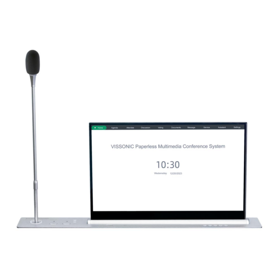
1. System overview 1.1. System features The NETLINK G2 series is a paperless multimedia conference system that replaces traditional paper with display screens. It utilizes network technology to connect information from each seat, promoting information sharing and interactive meetings. Designed for flexibility, practicality,... -
Page 8: System Composition
WWW.vissonic.com 1.2. System composition Components of the lifting screen system: Paperless Server VIS-SERVER-E2/E2S Full Digital Network DCP Conference Processor VIS-DCP2000-D/W Core Network Switch VIS-SWITCH24/48 Height-Adjustable Touch Screen VIS-15/17/18/21LSSC Height-Adjustable Touch Screen with Name plate VIS-15/17/18/21LDSC ... -
Page 9: Paperless Conference System
WWW.vissonic.com 2. Paperless conference system 2.1. Paperless Server VIS-SERVER-E2/E2S 2.1.1. Features and interfaces The controller for a paperless multimedia conference system is equipped with server software for this purpose. It offers a GUI based on a B/S (Browser/Server) architecture via the network. - Page 10 WWW.vissonic.com communication device and embedded system. 7,9. Dual network Used for data Communication, connectivity, protocol Support, ports remote Management 8. 2 USB 2.0 ports, Used for data storage or connecting to external devices. 2 USB 3.0 ports 9. Audio input/output...
-
Page 11: Installation
WWW.vissonic.com interface audios. 2.1.2. Installation The server can be installed inside a standard 19-inch rack with standard mounting screw holes. Figure 2.1.2 Mounting the server 2.1.3. Connection 2.1.3.1. Connecting the power supply Use the attached power cable to connect the conference controller to an external power socket. -
Page 12: Vis-Dcp2000-D/W Conference Controller
WWW.vissonic.com 2.1.3.2. Connecting the switch Configure the left network port of the dual network card settings server as the interface connected to the switch using CAT5e cable. This setup integrates the lift screen conference system. Figure 2.1.3.2 Server connect to switch 2.2. - Page 13 WWW.vissonic.com Figure 2.2.1 VIS-DCP2000-D/W front and rear panels Front panel: No./Name Description 1. Power Switch Power on or off the controller. 2. Display Show the current status or the result of operation, menu list etc. 3. Operate Buttons 4-direction buttons for menu operation, confirm and exit.
-
Page 14: Installation
WWW.vissonic.com terminal when the AEC acoustic echo cancellation function is used. 13. Audio Link Used for data transmission,and communication protocols. 14. CU/DU It is used to connect chairman unit, delegate unit, interpreter unit or POE speaker. Hand in hand loop connection can be made between port 1 and port 2 or between port 2 and port 3. -
Page 15: Connection
WWW.vissonic.com 2.2.3. Connection 2.2.3.1. Connecting the power supply Use the attached power cable to connect the conference controller to an external power socket. Figure 2.2.3.1 Power interface of the conference controller 2.2.3.2. Connecting to lifting screen MIC The CU/DU port of the controller via CAT5e cable is connected to the microphone control port at the bottom of the lifting screen to control the microphone's on/off switch. -
Page 16: Core Network Switch Vis-Switch24/48
WWW.vissonic.com Figure 2.2.3.3 Conference controller connects lifting screen MIC 2.3. Core Network Switch VIS-SWITCH24/48 2.3.1. Features and interfaces The switch acts as an intermediary device connecting the server, conference controller, and lifting screen units, enabling information exchange. This Core Network Switch is a crucial component designed to enhance the efficiency and functionality of your paperless system. -
Page 17: Installation
WWW.vissonic.com 2. 1000M SFP 2 Gigabit Ethernet ports 3.Reset Reset the switch. 4.Power interface Connect the power supply and switch Figure 2.3.1.2 VIS-SWITCH48 front panel No./Name Description 1. Ethernet interface 48 network interfaces are used to connect to different devices 2. -
Page 18: Paperless Lifting Screen Units
WWW.vissonic.com 2.4. Paperless lifting screen units This product leverages advanced intelligent technology to deliver an HD touch display, smart lifting, automatic elevation, and intelligent control within a sleek, integrated aluminum design. It offers features such as automation, theft prevention, dust protection, and desktop beautification. Its versatility makes it suitable for various environments, including conferences, command centers, offices, hotels, classrooms, and studios. - Page 19 WWW.vissonic.com Top Panel USB interface Screen: Tilt backward PC: On/Off Screen: Tilt forward Screen: Raise Screen: Stop Screen: Retract Figure 2.4.1.2 Lower panel interface of lifting screen Device Interface Description HDMI-2 Signal Input RS485/RS232 Control Port DC-12V Power Input...
-
Page 20: Vis-15/17/18/21 Ldsc, Vis-15/17/18/21 Ldsc-A
WWW.vissonic.com 2.4.2. VIS-15/17/18/21 LDSC, VIS-15/17/18/21 LDSC-A Retractable ultra-thin HD Screen with Nameplate: VIS-15/17/18/21 LDSC, Retractable ultra-thin HD Screen with Nameplate and integrated PC:VIS-15/17/18/21 LDSC-A Panel description: Figure 2.4.2.1 Top panel of lifting screen Top Panel USB interface Screen: Tilt backward... - Page 21 WWW.vissonic.com Figure 2.4.2.2 Lower panel interface of lifting screen Device Interface Description HDMI-2 Signal Input RS485/RS232 Control Port DC-12V Power Input...
-
Page 22: Vis-15/17/18/21 Lsscm,Vis-15/17/18/21 Lsscm-A
WWW.vissonic.com 2.4.3. VIS-15/17/18/21 LSSCM,VIS-15/17/18/21 LSSCM-A Retractable Ultra-thin Screen with MIC: VIS-15/17/18/21 LSSCM, Retractable Ultra-thin Screen with MIC and integrated PC: VIS-15/17/18/21 LSSCM-A Panel description: Figure 2.4.3.1 Top panel of lifting screen with MIC Device Panel (with microphone) Conference microphone: On/Off... - Page 23 WWW.vissonic.com Figure 2.4.3.2 Lower panel interface of lifting screen Device Interface Description HDMI-2 Signal Input RS485/RS232 Control Port DC-12V Power Input Conference MIC Interface: Figure 2.4.1.7 Bottom MIC interface of lifting screen Conference MIC Interface Description Conference MIC Input/Output...
-
Page 24: Vis-15/17/18/21 Ldscm,Vis-15/17/18/21 Ldscm-A
WWW.vissonic.com 2.4.4. VIS-15/17/18/21 LDSCM,VIS-15/17/18/21 LDSCM-A Retractable Ultra-thin Screen with MIC and Nameplate: VIS-15/17/18/21 LDSCM, Retractable Ultra-thin Screen with MIC and Nameplate and integrated PC: VIS-15/17/18/21 LDSCM-A Panel description: Figure 2.4.4.1 Top panel of lifting screen with MIC Device Panel (with microphone) - Page 25 WWW.vissonic.com USB interface Screen: Tilt forward PC: On/Off Screen: Stop Figure 2.4.4.2 Lower panel interface of lifting screen Device Interface Description HDMI-2 Signal Input RS485/RS232 Control Port DC-12V Power Input Conference MIC Interface: Figure 2.4.4.3 Bottom MIC interface of lifting screen...
-
Page 26: Integrated Pc Interface
WWW.vissonic.com 2.4.5. Integrated PC Interface Built-in integrated PC mode includes: Height-Adjustable Touch Screen VIS-15/17/18/21LSSC-A Height-Adjustable Touch Screen with Name plate VIS-15/17/18/21LDSC-A Height-Adjustable Touch Screen with Lifting MIC VIS-15/17/18/21LSSCM-A Height-Adjustable Touch Screen with Name plate and lifting MIC VIS-15/17/18/21LDSCM-A Integrated PC Interface Description... -
Page 27: Installation
WWW.vissonic.com 2.4.6. Installation Figure 2.4.6 Installation of lifting screen Notes Place the product on a stable surface or securely mount it on a desk. Connect the power adapter to the product's power port, then plug it into an AC100-240V, 50-60Hz power outlet. - Page 28 WWW.vissonic.com 2.4.6.1. Installation dimension Installation by Cutting Hole in Conference Table, the Lift Screen Dimensions are as Follows: Model VIS-LDSC/VIS-LSSC, VIS-LDSC-A/VIS-LSSC-A 15.6-inch Single 17.3-inch Single 18.5-inch Single 21.5-inch Single Category Screen Screen Screen Screen Product 422*70*553mm 458*70*553mm 488*70*603mm 560*70*603mm dimensions...
-
Page 29: Connection
WWW.vissonic.com 2.4.7. Connection 2.4.7.1. Connecting to power supply Power: Connect the lifting unit to an external power outlet using the provided power cable. Figure 2.4.7.1 Power interface of integrated PC 2.4.7.2. Connecting to switch Lifting screen with integrated PC The lifting screen is connected to the switch via the RJ45 port on the side of the integrated PC. - Page 30 WWW.vissonic.com various functions based on their roles. Permissions include: sign-in, agenda access, viewing topics and documents, topic voting, speaker camera tracking, speaking order list, on-demand live video, document approval and saving, file uploading, information communication, service application, viewing announcements, synchronous screen, following synchronous screen, conference projection, temporary permission management, and electronic nameplates.
-
Page 31: Rs485 Signal Enhancement Extension Unit Vis-Seu
WWW.vissonic.com According to the connection shown in the following figure, use the external client to achieve the switch of lifting screen. Figure 2.4.7.2.3 Connection of CLIENT controlling lifting screen power on/off (2) Connecting to switch The external client is connected to the switch via an Ethernet cable to achieve information interconnection. -
Page 32: Connection
WWW.vissonic.com Figure 2.5.1 RS485 signal enhancement extension unit panel No./Name Description 1,2.RS485B, RS485A The terminals of two communication lines, typically labeled as A and 3,4. Power interface Power supply, VCC represents “+”, GND represents “-”,9-40V DC 5,6.RS485A2,RS485B2 The second group connects to the lifting screen unit or other devices. -
Page 33: Screen Lift Control Via Rs485/Rs232
WWW.vissonic.com The lift screen units are cascaded using network cables through the RS485/RS232 port. Figure 2.5.2.2 Connect to lifting screen unit 2.5.3. Screen Lift Control via RS485/RS232 2.5.3.1. Interface details Cable “7” ”8“removed from the network cable corresponds to the RS485/RS232 protocol at the interface. -
Page 34: Control Panel Vis-Ck100
WWW.vissonic.com Raise FF/EE/EE/EE/DD Pause FF/EE/EE/EE/CC Control Screen Retract FF/EE/EE/EE/EE Display PC Signal FF/EE/EE/EE/60 Display HDMI Signal FF/EE/EE/EE/61 Raise FF/EE/EE/EE/D1 Control MIC Pause FF/EE/EE/EE/C1 Retract FF/EE/EE/EE/E1 Raise FF/EE/EE/EE/D2 Simultaneous Control of Pause FF/EE/EE/EE/C2 Screen and Mic Retract FF/EE/EE/EE/E2 Notes To ensure proper RS485/RS232 communication control: If unable to control the lifter, swap the two control lines ... -
Page 35: Connection
WWW.vissonic.com Figure2.6.1 VIS-CK100 front and rear panel Front panel: No./Name Description 1.All control Control screen and microphone overall lift and pause. 2.Screen control Control screen lift and pause. 3.Mic control Control Mic lift and pause. 4.Home button Back to home interface Rear panel: No./Name... -
Page 36: Distributed Encoder Vis-Ds200-I-P
WWW.vissonic.com corresponding cable, connects one end to the panel and then connects them on the RS485 signal enhancement extension unit, confirms the correct connection: A to A and B to B. Connect the two devices separately to the power adapter to power on. -
Page 37: Connection
WWW.vissonic.com Rear panel: No./Name Description 6.HDMI interface HDMI input, supports maximum resolution of 2K 7.1*USB2.0 Connect to keyboard or mouse and other devices 8.HDMI interface HDMI output, supports maximum resolution of 2K 9.Audio interface 3.5mm stereo audio input/output 10.Serial transmission 1 RS-485, 1 RS-232;... -
Page 38: Configuration Of Paperless System
WWW.vissonic.com 3. Configuration of Paperless System 3.1. Configuration of Conference System Server 3.1.1. Accessing the Web-Based Administration Panel To access the login page, open Google Chrome on another device within the server or local network and enter the address 192.168.1.244:8080. Use the default username "root" and password "123456"... -
Page 39: Seating Arrangement
WWW.vissonic.com 3.1.3. Seating arrangement Select [Room and Device] and click [Seat Management] select a room, and then drag the icons in the list on the left to the canvas on the right, such as, equipment(unit), speaker lists, title and other functions. -
Page 40: Default User
WWW.vissonic.com Edit the seat name of the unit and enter the unit ID. Please note: The unit ID must be bound to the corresponding seat name. (If the lift screen does not have a microphone, the unit ID can be set to For example: Name: Seat1, Unit ID: 1 In the client with ID 1, the seat name bound in the upper right corner must be "Seat1". - Page 41 WWW.vissonic.com Step 2: Open [Role Management], click on [Identity Management], then click on [Add] to add a new identity. Step 3: Click on the permissions of the role to assign permissions. Step 4: Check the required functions and click update.
- Page 42 WWW.vissonic.com Step 5: Click [User Management], click on [Add], enter user information, and click [OK]. For example: Create users named Lisa. Step 6: Click “+” to upload a user picture. (Optional)
-
Page 43: Set Unit Id
WWW.vissonic.com Step 7: Connect the IC card reader to the USB port of the server and turn on the IC card switch. Select the user, then put the IC card on the reader to read it and enter the IC card information of the corresponding user. -
Page 44: Add A Meeting
WWW.vissonic.com Step 4: Press the MIC button on the left side of the lift screen microphone to assign an ID number (starting from 1) to each lift screen microphone in sequence. Step 5: Press all units, then long-press the "ESC" key on the conference controller for about 2 seconds. -
Page 45: Register Device Serial Number
WWW.vissonic.com Right-click the seat to add permissions, set the host. The red seat is for the host. And click [save]. It's essential to add a host to the meeting; otherwise, the meeting cannot proceed normally. Click “Click to upload” to upload image background. -
Page 46: Bind Device Seat Name And Unit Id
WWW.vissonic.com Step 2: Click [download] at the top right to download the serial number. Send the file to the manufacturer for registration. After getting the registration file, click "upload" to import the registration file. The registered status is green. Usually, it will be registered before leaving the factory, so this step may not be needed. - Page 47 WWW.vissonic.com Step 2: Go to the client. Click the "VISSONIC" logo on the lift screen login page, the seat name binding will appear in the upper left corner, and the unique serial number of this device will appear in the lower left corner.
- Page 48 WWW.vissonic.com You can see that the device is bound to the seat name "Seat1". Click the "VISSONIC" logo again to hide the seat name and serial number. Once seating is assigned, users can log in on the client side. Method 2: Binding in the web page Step 1: Open [Device Registration] under [Room and Device].
-
Page 49: Add Meeting Files
WWW.vissonic.com Step 2: Find the corresponding serial number on the lift screen, confirm the ID of this device, and bind the corresponding seat name. For example, if the ID of this unit is 1, need to bind "Seat1" The device with this serial number has been bound to "Seat1". Once seating is assigned, users can log in on the client side. -
Page 50: Meeting Voting Topics
WWW.vissonic.com 3.1.10. Meeting voting topics Open [Room Reservation] and [Voting Management]. Select a meeting, click [Add], enter the voting name, select voting type, statistical type, sign in or anonymous, voting time, pass radio and details, and finally click [Confirm]. Note: If the voting type is election or rank, you need to click "discussion option", double-click the "option name"... -
Page 51: Meeting Agenda
WWW.vissonic.com 3.1.11. Meeting agenda Open [Room Reservation] and [Agenda Management]. Select a meeting, enter the agenda name. Choose the operation type (file or discussion), select the corresponding file or discussion (file or vote), enter the agenda description, and click [Add]. - Page 52 WWW.vissonic.com Note: The cameras, and other RTSP streaming devices connected to the switch need to be in the same network segment as the server, segment 1. You can then watch the video source in [Discussion] on the client. Camera's RTSP address format: rtsp://IP:554/1. Device type: Common type.
-
Page 53: Speaking Countdown
WWW.vissonic.com 3.1.13. Speaking Countdown To enable the speaking countdown, go to [Room and Device] [Device Management]. Add or edit a conference controller, enable the countdown, and set the time. -
Page 54: Control And Management
WWW.vissonic.com 3.1.14. Control and Management Backend control includes one-click power off, reboot, log out, and refresh. It also supports lift control with lift paperless terminals. 3.1.15. Control during the Meeting Microphone control: Open the [Microphone] in the [Control in Meeting]. Click the microphone icon. - Page 55 WWW.vissonic.com Sign-In Control: Open the [Sign-in] in the [Control in Meeting]. Easily start or end sign-in with a single click during the meeting. 3. Voting Control: Open the [Voting] in the [Control in Meeting]. Initiate or conclude voting, decision-making, elections, and other topics with one click during the meeting.
-
Page 56: Post Meeting Management
WWW.vissonic.com 3.1.16. Post meeting management After the normal conclusion of the non-seamless meeting: ● can export the content to be saved, including check-in information, voting information, meeting information, annotation files, etc.; ● can be saved as a folder directory. 3.1.17. Software update System management can be a key to update Windows client or Android client, will need to update file upload, click update Windows client or Android client. -
Page 57: Configuration Of Client
WWW.vissonic.com 3.2. Configuration of Client 3.2.1. Client user login Users log in to the client software, enter the user name and password in the login page, and then login to the main interface. -
Page 58: Main Client Screen
WWW.vissonic.com 3.2.2. Main client screen ● [Home]: Provide the name and time of the meeting. ● [Agenda]: The name of the current meeting and the meeting agenda, can be directly on the agenda. ● [Attendee]: Information and sign-in of participants. -
Page 59: User Check-In
WWW.vissonic.com 3.2.4. User check-in Open the [Attendee] interface, the interface of the host or assistant has a button to [initiate check-in] and [Stop check-in]. 3.2.5. Conference discussion Open the discussion interface, see the list of speakers, watch third-party video sources, camera... -
Page 60: Conference Speech
WWW.vissonic.com 3.2.6. Conference Speech Participants can control their microphones using the physical buttons on the speaker unit. The chairman unit has the additional option to mute, turn off or allow delegates to speak. In normal mode, the chairman unit can mute a delegate unit by pressing the veto button once, and close it by pressing it twice. -
Page 61: Conference Voting
WWW.vissonic.com 3.2.7. Conference voting The host or assistant opens the voting interface and selects a vote in the voting list on the left to quickly initiate a vote. The voting process can be viewed on the projection screen. After the voting is over, the voting results can be viewed in [Documents]. -
Page 62: Notes On Meeting
WWW.vissonic.com 3.2.9. Notes on Meeting After logging in to the client, each participant can annotate the meeting files; the annotations will be saved in the backend management terminal [Document Management], and [Document Management] will automatically generate a user-named folder to save the file information of the meeting annotations. -
Page 63: Conference Services
WWW.vissonic.com 3.2.11. Conference services Attendees can open service interface, call water, pen, assistant service and so on. 3.2.12. Assistant management The host or assistant opens the [Assistant] interface to manage the meeting. [Control] Select the participants to authorize/cancel, check or cancel the corresponding... - Page 64 WWW.vissonic.com [Announcement] Host or assistant can edit and publish the announcement. [Service] The host or assistant can view and respond to the services requested by the conference participants.
-
Page 65: Conference Settings
WWW.vissonic.com 3.2.13. Conference Settings Attendees to open the settings interface, can adjust log out, switching language, EQ, and to check the software version. [Setting up] You can view attendee name and logout, and turn on/off video loop playback (temporary). [Language] Can switch between different languages. - Page 66 WWW.vissonic.com [EQ] The sensitivity and 8-segment EQ of the microphone can be set. [Version] View client version.
-
Page 67: Screen Sharing
WWW.vissonic.com 3.2.14. Screen Sharing The host or assistant can initiate screen sharing or projection by clicking on the floating ball [Same screen] or [Projection]. If they have the necessary permissions, indicated by a red circle in the lower-right corner of the icon if permissions are absent. -
Page 68: Common Troubleshooting Solutions
WWW.vissonic.com 4. Common Troubleshooting Solutions Symptoms of Malfunction Solutions 1. Check if the server backend software is running properly. Unable Access Server 2. Verify that the entered IP address is 192.168.1.244:8080. Backend Administration Note: The colon should be entered in English.
Need help?
Do you have a question about the NETLINK G2 Series and is the answer not in the manual?
Questions and answers