
Related Manuals for vissonic CLEACON


Summary of Contents for vissonic CLEACON
- Page 1 CLEACON Full Digital Network DSP Conference system User Manual V1.3.9 Version VISSONIC ELECTRONICS LIMITED - 1 - VISSONIC ELECTRONICS LIMITED...
- Page 2 Please contact the qualified service personnel. ■ General information instructions It lists the factors leading to the unsuccessful operation or set and the relevant information to pay attention to - 2 - VISSONIC ELECTRONICS LIMITED...
- Page 3 ◆This product grounds by the grounding wires .To avoid electric shocks, grounding wires and the earth must be linked together. Before the - 3 - VISSONIC ELECTRONICS LIMITED...
- Page 4 28(Change the flow diagram) 1.3.4 Add WIFI model, flush model 2017.6.21 1.3.5 6.3Configure the AP 2017.6.27 7.5 Default setting 1.3.6 Update manual for AP 2020.4.8 1.3.7 COM port definition connection 2020.7.17 1.3.9 Adding menu and POE 2022.4.22 4 VISSONIC ELECTRONICS LIMITED...
-
Page 5: Table Of Contents
2.4 Splitter Box VIS-CNB ...................... 13 2.5 CLEACON Digital Networked Delegate/Chairman Unit-Table models ......13 2.6 CLEACON Modular Flush-mounting models ..............19 2.7 CLEACON Digital Networked Delegate/Chairman Unit- Array microphone ....21 3.System Design and Plan ....................... 22 4. Installation ........................... 23 4.1 Install in the 19’rack ...................... - Page 6 7.1 VIS-DCP2000 conference processor ................61 7.3 Simple interpreter desk VIS-DIC-T .................. 63 7.4 Chairman unit and delegate unit display and operation ............ 63 7.5 Default Setting On VIS-DCP2000-W, VIS-AP4C and VIS-WDC-T/VIS-WDD-T..64 8. Install and Test ..........................65 6 VISSONIC ELECTRONICS LIMITED...
-
Page 7: About This Manual
Do not disassemble the equipment without permission, to avoid damage to the internal electrical components and will void the warranty. The user manual give the installers and operators the guide to install, configure and operate the CLEACON system. Copyright: VISSONIC Electronics Limited. 7 VISSONIC ELECTRONICS LIMITED... -
Page 8: System Overview
2. System Overview The CLEACON system is based on the AUDIO-LINKTM audio distribution & processing technology and WiFi 2.4G/5G Hz technology. The system is combined with wired CAT5 and wireless units and can be used for voting and PC software control. -
Page 9: Full Digital Networked Dsp Processor Vis-Dcp2000
4. Audio Recording- Press to start/stop recording the audio of whole conference content 5. USB Slot- To insert USB disk (Up to 32G) for recording, with status light indicator which is flashing during the recording. 6. Headphone Socket- Headphone connection 7. Knob- Control volume level of the system 9 VISSONIC ELECTRONICS LIMITED... - Page 10 18.Keyboard-Connect to the camera control keyboard 19.Enthernet-Connect to PC or switch for the software control 20.Ground screw-Connect the processor unit to the ground 21.Power inlet-Connect the processor unit to the main power supply with a power cable. 10 VISSONIC ELECTRONICS LIMITED...
-
Page 11: Extension Main Unit Vis-Exm
1. Loop Through Chains-Connect with processor unit/last extension unit and next extension unit. 2. Repeated Chains-Provide 4 channels for delegate/chairman units. 3 Power indicator--Indicate status of the power inlet connection. 4.Power inlet-- Connect the extension unit with power cable. 11 VISSONIC ELECTRONICS LIMITED... -
Page 12: 5Ghz Conference Access Point Vis-Ap4C
2. Network port --connect to the AP port of processor unit or POE switch. 3.Reset button NOTE: The switch do NOT recommend to other devices, only connected with the main unit VIS-DCP2000 and max. 8 pieces of VIS-AP4C. 12 VISSONIC ELECTRONICS LIMITED... -
Page 13: Splitter Box Vis-Cnb
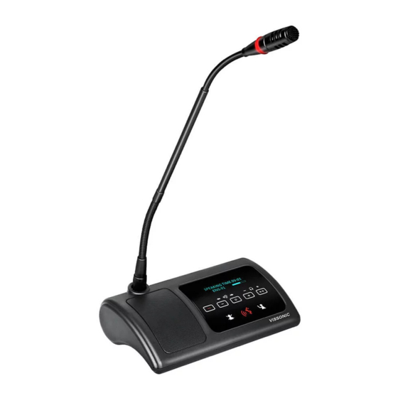
1. Repeated Chains -- spilt two chains for delegate/chairman units 2. Loop Through Chains --connect to the processor unit, extension unit or loop to next connection 2.5 CLEACON Digital Networked Delegate/Chairman Unit-Table models With the discussion units(wired and wireless),the delegates can make contribution to a conference. - Page 14 Figure 2.5 Top view of wired and wireless unit (1) 14 VISSONIC ELECTRONICS LIMITED...
- Page 15 Figure 2.6 Top view of wired and wireless unit (2) 15 VISSONIC ELECTRONICS LIMITED...
- Page 16 Figure 2.7 Side view of wired or wireless unit Figure 2.8 Side view of wired unit Figure 2.9 Side view of wireless unit 16 VISSONIC ELECTRONICS LIMITED...
- Page 17 Figure 2.10 Bottom view of wired unit Figure 2.11 Bottom view of wireless unit (1) Figure 2.12 Bottom view of wireless unit (2) 1.Microphone socket-Connects a pluggable gooseneck microphone(VIS-M600,VIS-M410 or VIS-M330) to the discussion units. 17 VISSONIC ELECTRONICS LIMITED...
- Page 18 14.CU/DU socket-Makes a loop-through in the CEALCON system with the discussion unit. 15.Power supply socket Connects a power supply adapter to the wireless discussion unit. 16.Battery pack compartment - Contains the battery pack (VIS-WBTY1) of the wireless discussion unit. 18 VISSONIC ELECTRONICS LIMITED...
-
Page 19: Cleacon Modular Flush-Mounting Models
2.6 CLEACON Modular Flush-mounting models Figure 2.13 Top view of modular flush mounting units 19 VISSONIC ELECTRONICS LIMITED... - Page 20 20. Connect to the MIC port on the model VIS-DCC-F, VIS-DCD-F or VIS-CSU-F unit 21.3.5mm audio cable on VIS-SPK-F speaker unit connect to the SPK1 or SPK2 port on the VIS-DCC-F, VIS-DCD-F or VIS-CSU-F unit 20 VISSONIC ELECTRONICS LIMITED...
-
Page 21: Cleacon Digital Networked Delegate/Chairman Unit- Array Microphone
2.7 CLEACON Digital Networked Delegate/Chairman Unit- Array microphone 1. Power indicator, red represents working status 2. High hardness speaker net, built-in 17 high-pointing pickups 3. The switch button, the chairman unit long press to start the priority mode, you can turn off the representative unit 4. -
Page 22: System Design And Plan
(with power relay devices it can load more devices). Here we list a basic capacity of active units for one processor control unit. VIS-DCP2000 VIS-EXM Extension Model cable Port Port Port Max. Port Port Port Port Max. total total VIS-DCC-T VIS-DCD-T VIS-DIC-T VIS-DID-T VIS-DVC-T 22 VISSONIC ELECTRONICS LIMITED... -
Page 23: Installation
4. Installation 4.1 Install in the 19’rack The central unit can be installed in a standard 19-inch cabinet. The unit has standard accessories of a pair of installation supports. See the following diagram for installation: 23 VISSONIC ELECTRONICS LIMITED... -
Page 24: Install In The Ap
3, install the fixing plate on pressure riveting screw under the machine; 4, fix the fixing plate with butterfly nut; 5, making M5X35 the butterfly screws go through the fixing plate to lock with desktop, so as to fix the equipment. As below: 24 VISSONIC ELECTRONICS LIMITED... -
Page 25: Connection
To connect the processor control unit to main power firmly Figure 5.1 CAUTION: Main power supply should well grounded, otherwise it may cause fatal incident 5.2 Audio inputs The processor control unit provides RCA or XLR type audio input connector. 25 VISSONIC ELECTRONICS LIMITED... -
Page 26: Audio Outputs
The processor control unit provides RCA , XLR or phoenix type audio output connector Figure 5.3 Audio output connection Type Signal Description Cinch Live Signal in Return Shield/Ground Xternal Positive Live Shield/Ground Return Negative Phoenix Positive Negative Shield/Ground 26 VISSONIC ELECTRONICS LIMITED... -
Page 27: Audio Link
5.4 Audio Link Use audio link socket to connect between the conference processor and use the VISSONIC tested CAT5E cable or better. 5.5 CU/DU Use the CU/DU socket to connect to the chairman/delegate unit or extension main unit and use the VISSONIC tested CAT5E cable or better. - Page 28 "Hand-in-Hand-Loop-Network" connection is only available between channel 1 and channel 2,or channel 2 and channel 3,but not valid between channel 1 and channel 3. 2.Hand in Hand Connection 3.Hand in Hand Connection+ Hand-in-Hand-Loop connection 28 VISSONIC ELECTRONICS LIMITED...
- Page 29 4.Connction box+ Hand-in-Hand-Loop connection 5.Extension Main Unit connection 29 VISSONIC ELECTRONICS LIMITED...
- Page 30 Use the AP socket to connect to the 2.4GHz/5GHz conference access point VIS-AP4C or switch(connected with VIS-AP4C)and use the CAT5 cable or better. NOTE: The switch do NOT recommend to other devices, only connected with the main unit VIS-DCP2000 and max. 8 pieces of VIS-AP4C. 30 VISSONIC ELECTRONICS LIMITED...
-
Page 31: Control
Bottom COM connected to cameras or HD camera auto tracking controller VIS-MSDI. COM port pin is described as follows: 1. RS-232 (DB9 female/pin type) pin definition (upper port of controller) Signal Description Null sending data Receiving data Null Signal ground 31 VISSONIC ELECTRONICS LIMITED... -
Page 32: Keyboard
Null Null Null Null 5.8 KEYBOARD Use the KEYBOARD socket to connect to the Camera controller with CAT5 cable. 5.9 ETHERNET Use the ETHERNET socket to connect to the PC and use CAT5 cable or better. 32 VISSONIC ELECTRONICS LIMITED... -
Page 33: Configuration
3.Press '△' ,'▽' to adjust parameters and press the 'ENTER' to confirm the options. The knob 'Master vol' is used to set the volume of master line out and the value directly display on the LCD. You can reference the bellowing menu structure to set the parameters 33 VISSONIC ELECTRONICS LIMITED... - Page 34 34 VISSONIC ELECTRONICS LIMITED...
- Page 35 35 VISSONIC ELECTRONICS LIMITED...
- Page 36 36 VISSONIC ELECTRONICS LIMITED...
- Page 37 A c t i v e M I C : 6 - > 6. Press the button 'ESC' back to the main menu. U n i t : 0 0 0 1 M I C : O v e r r i d e / 1 37 VISSONIC ELECTRONICS LIMITED...
-
Page 38: Dsp Menu
DSP1'->'AEC').Audio output 'OUT1', OUT2', OUT3' and 'OUT4' output the same audio. If you use the zone function, you need to open the audio zone function (menu 'Zone'-> 'Zone Setup'-> 'Enable'->'on'), and set other submenus under the 'Zone' menu, as shown in the table below. 38 VISSONIC ELECTRONICS LIMITED... - Page 39 ID Zone--that is, the ID range of the microphone set in Zone 4, the default ID starts from X3+1, and the ID zone is set to X4 (between X3+1~4000), then the microphone ID of Zone 4 is 39 VISSONIC ELECTRONICS LIMITED...
- Page 40 USB Recording Setup Use the menu items in 'Recording' sub-menu to set the recording parameters. Menu item Parameter Value Description Quality 32,64,96,128kbps Set the audio quality of MP3 for On/Off USB recording 40 VISSONIC ELECTRONICS LIMITED...
-
Page 41: Delegate Setup
Description Max. channel 02 to 32 Limit the channel number according to the need and reduce the operation on delegate units. Channel Set each Channel to bind with a language. Chinese,English,...(10 4 languages) Chinese,English,...(10 4 languages) 41 VISSONIC ELECTRONICS LIMITED... -
Page 42: Camera Auto-Tracking Setup & Application
.(There are no video set this menu) switcher connected to the main unit for camera tracking by RS232, just set as Off.) Note: To set next camera, we just repeat the same 42 VISSONIC ELECTRONICS LIMITED... - Page 43 VIS-MSDI Step 1.Connect the main unit to the cameras or camera auto-tracking controller VIS-MSDI with the bottom CONTROL port. 1. Use the VISCA protocol camera 43 VISSONIC ELECTRONICS LIMITED...
- Page 44 2. RS232 control conference tracking and recording all-in-one machine VIS-CRS05-A. Step 3 Set the camera information to the main unit by the front panel and adjust camera to shoot the position by remote controller ,keyboard controller or CLEACON conference software as the bellowing step flow.
-
Page 45: Network Setup
6.1.6 Network Setup Use the menu items in 'Network' sub-menu to set the IP address and MAC for processor unit. Menu item Parameter Value Description Option 1 000 to 255 Set the static IP for the processor. 45 VISSONIC ELECTRONICS LIMITED... -
Page 46: Poe Speaker
6.18 Configuration Setup Use the menu items in 'Configuration ' sub-menu to set the parameter for global system. Menu item Value Description Language CN/EN Change the language for main unit and delegate units (Note: We can 46 VISSONIC ELECTRONICS LIMITED... -
Page 47: Wifi Communication Setup
The default setting is OFF. If set as "On", the main unit will send the new SSID and PASSWORD to the wireless delegate/chairman unit. After all delegate/chairman unit is received SSID PASSWORD, please set the 'START SET 'menu as Off. 47 VISSONIC ELECTRONICS LIMITED... -
Page 48: Default' Setting
Just press the MIC button on every delegate/chairman units one by one and set the ID for them. Press the button ''ESC' around 2 seconds on the processor unit, the display exit from the 'Setting ID...' interface and back to main screen. The setting is saved and finished. 48 VISSONIC ELECTRONICS LIMITED... -
Page 49: Set The Unit Type
We press the MIC button on the unitand the display will shift cyclically as Delegate-Chairman-interpreter-VIP.Let the them display as what you want to set as. Chairman Interpreter Set on the processor unit to off the type setting as bellowing. 49 VISSONIC ELECTRONICS LIMITED... -
Page 50: Configure The Ap Channel
Internet protocol version 4 (TCP/IPv4), click on the properties below, set the same IP segment address for PC and AP. The default IP address for the For example, the network properties of our PC are shown in the following figure: 50 VISSONIC ELECTRONICS LIMITED... -
Page 51: Computer Login To Ap
1. 192.168.2.1, log on to AP through a computer browser to set up. 2. Enter user name admin, password admin. 3. After logging in to the main interface,click 5.8G Configuration on the settings navigation menu on the left. 4. Click Setting 5. Click Scan As shown below 51 VISSONIC ELECTRONICS LIMITED... - Page 52 AP (WiFi_CONFERENCE) occupation channel 48 and other AP occupation 5G channels. 7. Click the return button to select the unused channel, which is currently available between 36 / 48149 / 165 to select the unoccupied channel. 52 VISSONIC ELECTRONICS LIMITED...
-
Page 53: Configure The Ap Vis-Ap4C
9-bit host and unit By default:88888888 Start Set On/Off Turn off OFF,by default and turn on If SSID and PASSWORD ,are changed,the SSID PASSWORD set by the host will be sent to the WIFI wireless unit. 53 VISSONIC ELECTRONICS LIMITED... - Page 54 ENTER key to select the next character,To determine the name such as “WIFI_VISSONIC”,press ESC to return Out, next set the PASSWORD,operation as above, change the password to “88888888” press ESC to exit. 54 VISSONIC ELECTRONICS LIMITED...
- Page 55 Step 3 Shows that after the update is successful,set up the Start set: off,and manually reschedule all microphone units,all units display unable to connect to the controller ,constantly status, at the AP needs to be updated. Wireless Connection 55 VISSONIC ELECTRONICS LIMITED...
-
Page 56: Set Up Ap Ssid And Password
Internet protocol version 4 (TCP/IPv4), click on the properties below, set the same IP segment address for PC and AP. The default IP address for the For example, the network properties of our PC are as follows: 56 VISSONIC ELECTRONICS LIMITED... - Page 57 SSID name set by the conference controller. As shown in the figure, multiple names can be set. For example, we add the name``WIFI_VISSONIC'' . After setting, click Submit at the bottom of the page for 15 seconds for upload and saving. 57 VISSONIC ELECTRONICS LIMITED...
- Page 58 Key, and finally click the Submit upload below to save, the meeting unit has the display date and time, that is, the connection setting is successful. Notes : Wireless system Troubleshooting When there is noise from wireless unit internal speaker or external loudspeaker 58 VISSONIC ELECTRONICS LIMITED...
- Page 59 – The VIS-AP4C has a typical Wi-Fi coverage distance of 30 m. 4. If there is more than one VIS-AP4C, need to set the two AP with different channel. 5. Press follow button to SCAN existing AP and their channels. (search 5G signal only) 59 VISSONIC ELECTRONICS LIMITED...
- Page 60 Scan result like below, there are 6 AP nearby, channel is 48,52,36,157,161 60 VISSONIC ELECTRONICS LIMITED...
-
Page 61: Operation
On the main screen, press the button '▽' and directly enter the sub-menu of MIC mode to set the microphone mode. When the conference processor is connected to the PC, you also can set the microphone mode from the PC software. Menu item Value Description MIC mode Override The microphone mode Open CLEACON 61 VISSONIC ELECTRONICS LIMITED... - Page 62 Active MIC 1,2,4,6 Limited the max number of active microphone. Monitoring -Unit information Menu item Value Description UNIT 0000~4000 Show the quantity of delegates/chairman units that connected to the system and help to check the system fault. 62 VISSONIC ELECTRONICS LIMITED...
-
Page 63: Simple Interpreter Desk Vis-Dic-T
The colors of the LEDs of the microphone buttons, the LED ring of MICand display show the condition of the microphone that connected to the discussion unit. MIC button color LED ring color Display character Condition Red(on) Red(on) Mic on Microphone enabled 63 VISSONIC ELECTRONICS LIMITED... -
Page 64: Default Setting On Vis-Dcp2000-W, Vis-Ap4C And Vis-Wdc-T/Vis-Wdd-T
Press the reset key on the back of the AP for about 10 seconds,The indicator is off,release the reset key .Press the reset key long again, the indicator light begins to flicker, and the AP has returned to the factory settings. 64 VISSONIC ELECTRONICS LIMITED... -
Page 65: Install And Test
1. From the main screen, press the 'Enter' button to get the following menu. M e n u - > M I C M o d e 2. Press the 'button' to select the maximum number of microphones on menu ActiveMIC. 65 VISSONIC ELECTRONICS LIMITED... - Page 66 5. Press' ENTER' to confirm the current parameter'6 / and make the parameter take effect, displayed as ActiveMIC:6. 6. Press' ESC' to return to the home screen. 3.Change the AP band according to the field wireless network environment. For specific operations, see 6.3 AP band configuration. 66 VISSONIC ELECTRONICS LIMITED...
Need help?
Do you have a question about the CLEACON and is the answer not in the manual?
Questions and answers