
Related Manuals for vissonic CLASSIC-D


Summary of Contents for vissonic CLASSIC-D
- Page 1 CLASSIC-D Full Digital Network Conference system User Manual V2.0 VISSONIC ELECTRONICS LIMITED...
- Page 2 The meaning of symbols ■ Safety instructions For your safe and correct use of equipment, we use a lot of symbols on the equipment and in the manuals, demonstrating the risk of body hurt or possible damage to property for the user or others. Indications and their meanings are as follow.
- Page 3 Important note Warning ◆This product grounds by the grounding wires. To In order to ensure the reliable performance of the equipment and the safety of the user, please observe avoid electric shocks, grounding wires and the earth the following matters during the process of must be linked together.
- Page 4 Version Version Update Date 2018.08.06 Adding VIS-DOC/DOD-T, modifying Camera 2023.06.28 Track.
-
Page 5: Table Of Contents
Content 1. About this manual ......................... 1 Safety Instructions........................1 2. System Overview .......................... 2 2.1 Conference Controller VIS-DCP1000 ................3 2.2 Conference Unit VIS-DEC-T/VIS-DED-T ................. 4 2.3 Conference Unit with Physical Button VIS-DOC-T/VIS-DOD-T ........6 3. System Design and Plan ........................ 9 3.1 Install in the 19’... -
Page 6: About This Manual
Do not disassemble the equipment without permission, to avoid damage to the internal electrical components and will void the warranty. The user manual gives the installers and operators the guide to install, configure and operate the CLEACON system. Copyright: VISSONIC Electronics Limited. Page 1... -
Page 7: System Overview
2. System Overview The CLASSIC-D system is based on the AUDIO-LINK audio distribution and processing technology. The system is combined with wired CAT5 and can be used for camera tracking and simultaneous controlling by PC software. Figure 2.1 CLASSIC-D system overview The CLASSIC-D system comprises: ... -
Page 8: Conference Controller Vis-Dcp1000
2.1 Conference Controller VIS-DCP1000 The full digital networked conference controller VIS-DCP1000 controls all the units in the chain, and supplies power to all. You can configure it by the button on front panel. Figure 2.1.1 Front and rear view of VIS-DCP1000 On front panel, the controller contains: 1. -
Page 9: Conference Unit Vis-Dec-T/Vis-Ded-T
CU/DU port 2 or CU/DU port 2 and CU/DU port 3 can be the closed loop. 13. Control - Female DB9 connector is used to connect with camera auto-tracking controller. 14. Control - Male DB9 connector is used to connect with the camera (or third-party central control device). - Page 10 Figure 2.2.2 Full Digital Discussion Delegate Unit VIS-DED-T 1. Microphone Socket - Connect a pluggable gooseneck microphone (Model no.: VIS-M330, VIS-M410, VIS-M485, VIS-M600) to the discussion units. 2. Loudspeaker - Give the audio signal from the floor to the delegate unit, when the microphone is enabled, the signal of the loudspeaker is muted.
-
Page 11: Conference Unit With Physical Button Vis-Doc-T/Vis-Dod-T
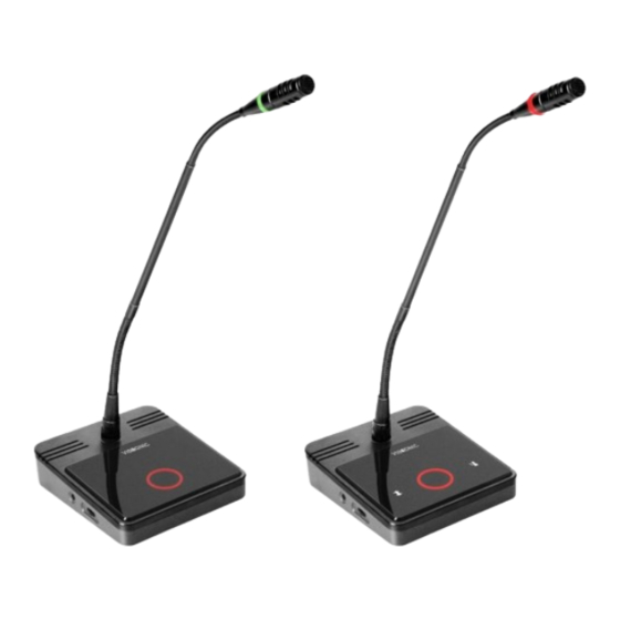
2.3 Conference Unit with Physical Button VIS-DOC-T/VIS-DOD-T Figure 2.3.1 Full Digital Discussion Chairman Unit with Physical Button VIS-DOC-T Page 6... - Page 12 Figure 2.3.2 Full Digital Discussion Delegate Unit with Physical Button VIS-DOD-T Page 7...
- Page 13 ① Microphone Socket - Connect a pluggable gooseneck microphone (Model no.: VIS-M330, VIS-M410, VIS-M485, VIS-M600) to the discussion units. ② Loudspeaker - Give the audio signal from the floor to the delegate unit, when the microphone is enabled, the signal of the loudspeaker is muted.
-
Page 14: System Design And Plan
3. System Design and Plan Before using our conference system, there are some basic points for you to plan/design a conference room. The controller is powered by 110V to 220V wide range power supply, while it has a basic control capacity (with power relay devices it can load more units). -
Page 15: Install In The 19' Rack
3.1 Install in the 19’ rack The conference controller VIS-DCP1000 can be installed in a standard 19-inch cabinet. The unit has standard accessories of a pair of installation supports. Below is the following diagram for installation: Figure 3.1 Installation of the conference controller... -
Page 16: Connection
4. Connection 4.1 Power supply Figure 4.1 Power connection Connect the conference controller and the power supply firmly together. CAUTION: Main power supply should well grounded, otherwise it may cause fatal incident. 4.2 Audio inputs Figure 4.2 Audio input connection The conference controller provides RCA or XLR type audio input connector. -
Page 17: Audio Outputs
4.4 CU/DU Figure 4.4 CU/DU port Use the CU/DU socket to connect to the chairman/delegate unit or extension main unit. Use the VISSONIC tested CAT5e cable or better. There are three connection ways available for CLASSIC-D conference system. Page 12... - Page 18 Hand in Hand Loop Network Hand in Hand Loop Network is an important feature for CLASSIC-D conference system. You can use this connection way to make the system steadier. Figure 4.4.1 Hand in Hand Loop Network connection “Hand-in-Hand-Loop-Network” connection is only available between CU/DU1 and CU/DU2, or CU/DU2 and CU/DU3, but not valid between CU/DU1 and CU/DU3.
- Page 19 Hand in Hand connection + Hand in Hand Loop connection Figure 4.4.3 Hand in Hand connection + Hand in Hand Loop connection Extension Main Unit + Hand in Hand Loop connection Figure 4.4.4 Extension Main Unit + Hand in Hand Loop Connection...
-
Page 20: Control
4.5 CONTROL Figure 4.5.1 Control Port Full digital conference system can be compatible with various control systems via RS232 serial interface. The upper COM port is used to connect with camera auto-tracking controller for camera auto-tracking function. The lower COM port is used to connect the camera (or third-party central control device). -
Page 21: Ethernet
RS232 (DB9 female/pin type) pin definition (Upper COM of conference controller) Signal Description Null Sending data Receiving data Null Signal ground Null Null Null Null RS232 (DB9 male/pin type) pin definition (Lower COM of conference controller) Signal Description Null... -
Page 22: Configuration And Operation
On the main screen, press the button “Mode” to set the microphone mode. When the conference controller is connected to the PC, you also can set the microphone mode from the PC software. Button Value Description Open Apply The microphone mode of CLASSIC-D conference MIC mode Voice system Override Mode Description In the open mode, the delegate unit directly turns on and off the microphone through the microphone switch button. - Page 23 In the apply mode, delegates can apply for turning on their microphones with the microphone button and the green LED on MIC will be on. When the chairman unit press the APROVAL button to enable the Apply applying delegate microphone according to the applying order. When the maximum number of delegates speaker, the system allowing the same maximum number of applying microphone on the waiting list.
-
Page 24: Turn On/Off The Built-In Speaker Of The Delegate/Chairman Unit
5.1.2 Turn ON/OFF the built-in speaker of the delegate/chairman unit Figure 5.1.2 Button of VOLUME Press the button “VOLUME▲” and “VOLUME▼” at the same time and hold, all indicators will be lighting and off. The setting is accepted and the speaker built-in delegate/chairman unit be on/off status reversely. -
Page 25: Setting The Default System
5.1.4 Setting the default system Figure 5.1.4 Button of Switch, MODE and ACTIVE MICRO’S 1. Turn off the system. 2. Press the button “MODE” and “ACTIVE MICRO’S” at the same time and hold. 3. Switch on the system. 4. All the indicators will be lighting on/off two times and release the buttons. - Page 26 Use CAT5 network cable to connect the network port of the PC and the Ethernet port of the VIS-DCP1000. Click the "Connect" button on the software and start set the camera tracking. Figure 5.1.6 Connect VIS-DCP1000 Figure 5.1.7 Camera setting interface...
- Page 27 Menu item Parameter Value Description Protocol SAMSUNG, Select the protocol according to the PELCO- D, camera model. VISCA, If a third-party central control device CUSTOM is used, it needs to be set to “CUSTOM”, and there is no need to set the submenus “Camera map”,...
- Page 28 Step 7: Select “02” on “Camera No.:” to choose camera no.2. Step 8: Execute steps 2 to 6 to complete the tracking settings of camera “02”. In the same way, complete the settings of all remaining cameras. Step 9: After setting the last microphone of the last camera, operate the camera to aim at the full view of the meeting (you can consider the chairman unit as the full view).
-
Page 29: Chairman/Delegate Unit Operation
If using the VISCA or the SAMSUNG/PELCO-D protocol: Enter the submenu “Camera map”, select a camera, set the address of the camera and bind it. For details, refer to the menu parameter description in this chapter; According to “Tracking setting steps”, set all cameras by the “VIS-DCP1000 Conference Controller Setup Software”... - Page 30 4/F, Building 6, No. 50 Nanxiang 1st Road, Huangpu District, Guangzhou, China • Tel: +86-020-82515140 • E-mail: info@vissonic.com @2023 VISSONIC Electronics Ltd. all rights reserved.
Need help?
Do you have a question about the CLASSIC-D and is the answer not in the manual?
Questions and answers