
Related Manuals for vissonic CLEACON


Summary of Contents for vissonic CLEACON
- Page 1 CLEACON Full Digital Network DSP Conference System User Manual V4.0 VISSONIC ELECTRONICS LIMITED...
- Page 2 The meaning of symbols ■ Safety instructions For your safe and correct use of equipments, we use a lot of symbols on the equipments and in the manuals, demonstrating the risk of body hurt or possible damage to property for the user or others.
- Page 3 Important note Warning In order to ensure the reliable performance of the equipment and the safety of the user, please observe the following matters during the process of installation, use and maintenance: The matters needing attention of installation Please do not use this product in the following places: the place of dust, soot and electric conductivity dust, corrosive gas, combustible gas;...
- Page 4 Matters needing attention in discarding product Electrolytic explosion: the burning of electrolytic capacitor on circuit boards may lead to explosion; Please collect and process according to the classification, do not put into life garbage; Please process it as industrial waste, or according to the local environmental protection...
- Page 5 Please use the latest user manual. The copyright of the manual belongs to VISSONIC ELECTRONICS LIMITED. This manual is protected by the Copyright Law of the People's Republic of China and other intellectual property laws and regulations.
-
Page 6: Table Of Contents
Contents 1. System overview ........................... 8 1.1 System features ........................8 1.2 System composition ......................11 2. Conference controller ........................13 2.1 VIS-DCP2000-D/W conference controller ............... 13 2.1.1 Features and interfaces ................... 13 2.1.2 Installation ......................15 2.1.3 Connection ......................15 2.1.3.1 Connecting the power supply .............. - Page 7 3.2.3 Settings and usage ....................57 3.2.3.1 Setting unit ID ..................... 57 3.2.3.2 Setting unit types and rights ................ 58 3.2.3.3 Usage ......................58 3.3 VIS-MAU-T unit ....................... 62 3.3.1 Features and interfaces ................... 62 3.3.2 Connection ......................63 3.3.3 Settings and usage ....................
- Page 8 4.3.3 Usage ........................100 4.3.3.1 Setting operator ..................100 4.3.3.2 Screen contents ..................101 5. Extension devices ........................103 5.1 VIS-EXM extension main unit ..................103 5.2 VIS-CNB splitter box ...................... 103 5.3 VIS-HL network cable ....................104 6. AP .............................. 105 6.1 Features and interfaces ....................
-
Page 9: System Overview
1. System overview 1.1 System features CLEACON series of full digital network DSP conference system, based on VISSONIC’s self- developed AUDIO-LINK voice distribution and processing technology, can offer the features of discussion, voting, interpretation, sign-in, and control by computer software. The system supports audio zoning, USB voice recording and monitoring, and camera tracking. - Page 10 Figure 1.1.1 Wired conference system...
- Page 11 Figure 1.1.2 Wireless conference system...
-
Page 12: System Composition
1.2 System composition A basic VISSONIC wired conference system consists of a conference controller, conference units, and CAT5e cables. An extension main unit VIS-EXM can be added for connecting more conference units or increasing the communication distance. A splitter box VIS-CNB can be added for connecting an array unit. - Page 13 Wireless Digital Discussion Chairman/Delegate Unit VIS-WDC-T/VIS-WDD-T Wireless Digital Discussion+Voting Chairman/Delegate Unit VIS-WVC-T/VIS-WVD-T Wireless Digital Discussion+Voting IC Card Chairman/Delegate Unit VIS-WVCIC-T/VIS- WVDIC-T 5G Wireless Multimedia Conference Unit VIS-MAW-T 64 Channels Interpreter Desk VIS-INT64 Extension Main Unit VIS-EXM ...
-
Page 14: Conference Controller
2. Conference controller 2.1 VIS-DCP2000-D/W conference controller 2.1.1 Features and interfaces VIS-DCP2000-D is a wired conference controller that supports wired Ethernet connection. This controller controls all connected conference units and supplies power to these units through POE. VIS-DCP2000-W is a wireless conference controller that supports 5G WiFi wireless connection and wired Ethernet connection. - Page 15 5. USB Slot To insert USB disk (Up to 32G, FAT32) for recording, with status light indicator which is flashing during the recording. 6. Headphone Socket Headphone connection. 7. Knob Control volume level of the system. Rear panel: Interface Introduction RCA audio input from external audio sources like MP3.
-
Page 16: Installation
2.1.2 Installation The conference controller can be installed in a standard 19-inch cabinet. On both sides of the front panel are standard screw holes for mounting the conference controller in the cabinet. The installation diagram is as follows. Figure 2.1.2 Mounting the conference controller 2.1.3 Connection... -
Page 17: Connecting Audio Inputs
Warning: The controller power supply needs to be well grounded to avoid accidents that endanger personal safety. 2.1.3.2 Connecting audio inputs The conference controller provides two types of audio input ports, RCA and XLR. The port diagram and pin descriptions are as follows. -
Page 18: Connecting The Conference Controller
VIS-EXM extension main units, or POE speakers. VIS-CNB can be used to connect more units. VIS-EXM can be connected to increase the capacity and transmission distance. VISSONIC offers dedicated CAT5e cables for connection. You can also purchase qualified CAT5e cables. -
Page 19: Connecting An Ap (Only For Vis-Dcp2000-W)
Figure 2.1.3.5 CU/DU conference unit ports 2.1.3.6 Connecting an AP (only for VIS-DCP2000-W) Figure 2.1.3.6 AP port The AP port of wireless conference controller is used for connecting to VIS-AP4C 2.4 GHz/5.0 GHz AP. If multiple VIS-AP4C APs are used, connect the AP port of the conference controller to a POE switch or a VIS-CNB splitter box, through which the controller connects to the VIS-AP4C APs. - Page 20 Figure 2.1.3.7.1 CONTROL interface The upper COM port is a female connector for connecting a VIS-CATC-A/B camera tracking controller, which is used to switch channels during camera tracking. The following table lists the default commands for channel switching. If want to customize the commands, contact us for online firmware update.
-
Page 21: Connecting The Pc Software
The ETHERNET port of the conference controller can be connected to a PC directly for using the VISSONIC conference management software, or connected to a switch through which the conference controller communicates with the PC. Use a standard network cable to connect this port. -
Page 22: Settings And Usage
2.1.4 Settings and usage 2.1.4.1 Menu and operations After completing the installation and connection of a conference system, use the buttons on the front panel of the conference controller to operate the menu and complete related settings on the display screen before starting a conference. - Page 23 Menu MIC Mode Override,Open,Voice,Apply Active MIC 1,2,4,6 Volume Line in 0 to -40dB,Mute Line out 0 to -40dB,Mute Remote in 0 to -40dB,Mute Enable On/Off DSP1 AFC-ANC 6dB,12dB,18dB,24dB,Off AFC Enable On/Off AFC-Lever 1,2,3,4,5 AEC Enable On/Off AEC-ANC 3dB,5dB,7dB,9dB,11dB,13dB,Off Zone...
- Page 24 Recording Quality 32,64,96,128kbps On/Off Delegate Setup Unit Info. Total Units:0000 to 4000 Time Enable On/Off Hour 00 to 23 Minute 00 to 59 Second 00 to 59 Year 2016 to 2115 Month 01 to 12 Date 01 to 31...
- Page 25 Network Option 1 000 to 255 Option 2 000 to 255 Option 3 000 to 255 Option 4 000 to 255 Enter Save/Exit Option 1 000 to 255 Option 2 000 to 255 Option 3 000 to 255 Option 4...
- Page 26 Menu MIC Mode Override,Open,Voice,Apply Active MIC 1,2,4 Volume Line in 0 to -40dB,Mute Line out 0 to -40dB,Mute Remote in 0 to -40dB,Mute Enable On/Off DSP1 AFC-ANC 6dB,12dB,18dB,24dB,Off AFC Enable On/Off AFC-Lever 1,2,3,4,5 AEC Enable On/Off AEC-ANC 3dB,5dB,7dB,9dB,11dB,13dB,Off Zone...
- Page 27 Recording Quality 32,64,96,128kbps On/Off Delegate Setup Unit Info. Total Units:0000 to 4000 Time Enable On/Off Hour 00 to 23 Minute 00 to 59 Second 00 to 59 Year 2016 to 2115 Month 01 to 12 Date 01 to 31...
- Page 28 Network Option 1 000 to 255 Option 2 000 to 255 Option 3 000 to 255 Option 4 000 to 255 Enter Save/Exit Option 1 000 to 255 Option 2 000 to 255 Option 3 000 to 255 Option 4...
-
Page 29: Setting Mic Mode
Enter the top-level menu on the home screen, press "▼" or "▲" to enter the setting screen of the MIC mode or the maximum number of simultaneously active microphones of delegate units. If the conference controller is connected to a PC, also can use the VISSONIC conference management software for setting. -
Page 30: Setting Dsp
Press the "ENTER" button to enter the menu; Press the "▼" button to select the value "6"; Press "ENTER" to make the current value "6" take effect and display it on the first line of the current screen; The setting is successful, press "ESC" to return to the home screen. - Page 31 Active Noise Cancellation (ANC) up to 24dB. ANC is disabled when the parameter is set to Off. Note: 1. When audio zoning is disabled (select "Zone"→"Zone Setup"→"Enable"→"Off"), 6dB, 12dB, 18dB, DSP1 processes the output audios of OUT1, AFC-ANC 24dB, Off OUT2, OUT3, and OUT4 at the same time with the same effect.
-
Page 32: Setting Audio Zones
2.1.4.4 Setting audio zones The "Zone" menu is used to set the audio zone and its output volume, and to select the audio channel output to the remote terminal. The zone is off by default, and AEC of "DSP1" is also off by default (menu "DSP"→"DSP1"→"AEC Enable"→"Off"), and the OUT1, OUT2, OUT3 and OUT4 ports output... - Page 33 Zone 2 to OUT3. If set Mute, no audio is sent to OUT3. Default is Mute. Zone 4 Gain 0 to -40 dB, Mute Zone 4 Gain: Set the audio gain of unit microphones in Zone 2 to OUT4. If set Mute, no audio is sent to OUT4.
- Page 34 Zone 4 Gain 0 to -40 dB, Mute Zone 4 Gain: Set the audio gain of unit microphones in Zone 4 to OUT4. If set Mute, no audio is sent to OUT4. Zone Setup Enable On/Off Turn on or off the audio zone function.
-
Page 35: Setting Recording
Turn off zone The following is an example of zone settings: Unit IDs are used to determine the range of microphones in a zone. The range of Zone 1 starts from 1 to the configured maximum ID by default. For example, if the maximum ID in Zone 1 is set to 15, the units with IDs in the range from 1 to 15 are in Zone 1 and audios from the zone are output from OUT1 by default. -
Page 36: Setting Conference Unit
Menu item Parameter Parameter value Description Quality 32, 64, 96, 128 kbps Sets the quality of sound recorded in MP3 format. On/Off Enables or disables ANC for noise suppression during recording. For example, to set 32kbps quality. Enter the menu "Recording"→"Set"→"Quality", and refer to the example in Section 2.1.4.4 for setting the value. - Page 37 ANC) EQ Select All, Host, XXXX Devices for which EQ needs to be set. "All" indicates all devices. "Host" indicates the conference controller. "XXXX" indicates a working conference unit with the ID XXXX (such as ID 0001 or ID 0002).
-
Page 38: Setting Interpreter Unit
Turn off the speaker of delegate unit (menu "Delegate Setup"→"Speaker"→"Off"): 2.1.4.7 Setting interpreter unit Enter the "Interpretation" menu to set related parameters of an interpreter unit. Menu item Parameter Parameter value Description Max. channel 02 to 32 Limit the channel number according to the need and reduce the operation on unit. -
Page 39: Setting Camera Tracking
Channel lock On/Off On-The interpreter unit cannot be changed the output channel. Off-The interpreter unit can be changed the output channel. Booth setup Max. booth 02 to 32 Max. booth--set the booth quantity. Start set On/Off On--All interpreter units will show the booth number for options. - Page 40 Off. Note: Repeat the following operations to set the next camera: "Camera Select"→"Camera addr" →"Video channel". The conference controller records the parameter settings of each camera. UDP addr Off, 001 to 255 UDP addr: Bind the IP address of a network camera.
- Page 41 The delay time ranges from 0 to 30 seconds. Video Mode Normal/Recorder Two video modes are optional. Select "Recorder" when VIS- CRS02/03/04/05B or VIS- CRS02/03/05A is used. Camera Track On/Off Enables or disables the camera tracking feature.
-
Page 42: Setting Network Address
Enter the "Start Set" submenu, and then use the camera remote control, keyboard, or CLEACON software to set the tracking position for each camera one by one. For the operation details, see the description of menu parameters in this section. - Page 43 16 POE speakers can be adjusted. Volume Select All POE Speaker All POE Speaker: Select this item, the knob on the front panel of the main unit will adjust the volume of the POE speaker; Line out...
-
Page 44: Setting System Configuration
2.1.4.11 Setting system configuration Enter the "Configuration" menu to set the configuration of the conference system. Menu item Parameter/Value Description Language CH/EN Change the language for delegate/chairman unit (Note: We can change the language according to your need by updated the firmware). -
Page 45: Setting Wireless Communication (Only For Vis-Dcp2000-W)
2.1.4.12 Setting wireless communication (only for VIS-DCP2000-W) Enter the "WiFi" menu to set the wireless network. Menu Parameter/Value Description item SSID 16 bits 16 bits SSID, Default setting is WIFI_CONFERENCE. Password 8 bits 8 bits password for communication between controller to the wireless conference unit, default password is 88888888. -
Page 46: Restoring To Factory Settings
Press "▼" to check all connected conference units one by one until "End Of Test" is displayed. All microphones are turned off at the end of the test. Press "ESC" to exit the manual mode. -
Page 47: Conference Units
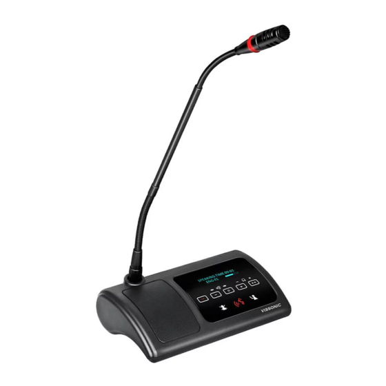
3. Conference units 3.1 VIS-DCC/DCD/DVC/DVD/DVCIC/DVDIC/DIC/DID /DSC/DSD-T units 3.1.1 Features and interfaces The conference units in this series are desktop wired digital units that use CAT5e cables for communication. The product models and features are as follows: CAT5 Wired Digital Discussion Chairman/Delegate Unit VIS-DCC-T/VIS-DCD-T ... - Page 48 Figure 3.1.1.1 Top view of wired units VIS-DCC/DCD/DVC/DVD/DVCIC/DVDIC-T...
- Page 49 Figure 3.1.1.2 Top view of wired units VIS-DIC/DID/DSC/DSD-T...
- Page 50 Figure 3.1.1.3 Left view and right view of wired units Figure 3.1.1.4 Rear view of wired units Figure 3.1.1.5 Interfaces on the bottom of a wired unit No./Name Description 1. Microphone socket Connects a pluggable gooseneck microphone (VIS-M600, VIS-M410 or VIS-M330).
-
Page 51: Connection
3. 5 multi-function buttons Apply the voting, volume adjustment for headphones, channel selector to select the channel that is sent to the headphone. 4. Loudspeaker When the microphone is enabled, the signal of the loudspeaker is muted. 5. Microphone button Turn on or off the microphone. -
Page 52: Settings And Usage
3.1.3 Settings and usage After the connection of all units, need to set the ID of each conference unit before using the conference system for the first time. (If replace a unit with a new one or add a new unit, be sure to reset the new unit ID to prevent ID conflicts.) -
Page 53: Setting Unit Types
Long press "ESC" on the front panel of the conference controller for about two seconds. The system enters the ID editing status. The display on the LCD screen is as follows: 3. Press the MIC button of each conference unit one by one. (The button turns into red.) Each unit is assigned with an ID.number. -
Page 54: Usage
Set as the above screen, all the VIS-DIC-T are worked as the delegate units. Next set the as "Type: ON". Check all VIS-DIC-T conference units, the display shows "delegate" unit; Press the MIC button on the unit and the display will shift cyclically as Delegate-Chairman- Interpreter-VIP. - Page 55 Please wait... VIS-DIC-T Screen Description Main screen. "Interpreter unit": Unit type. "Out:01 ENG": show the interpreter unit output to channel number and language name. Press the channel buttons to change the output channel. Volume bar to show the volume level...
-
Page 56: Vis-Dmd-T Unit
3.2 VIS-DMD-T unit 3.2.1 Features and interfaces VIS-DMD-T is a wired multimedia digital conference unit with a 5.0-inch (800×480) touch screen. This unit uses CAT5e cables for communication. The unit can be set as a chairman unit, delegate unit, VIP unit, or a dual-user unit according to the actual requirements of a conference. -
Page 57: Connection
Figure 3.2.1.3 Right view of VIS-DMD-T Figure 3.2.1.4 Rear view of VIS-DMD-T No./Name Description 1. Microphone socket Connects a pluggable gooseneck microphone (VIS-M600, VIS- M410 or VIS-M330). 2. OLED display Display the MIC status, volume bar, interpretation channel, voting information, speaking time, clock and date. -
Page 58: Settings And Usage
3.2.3 Settings and usage 3.2.3.1 Setting unit ID After the connection of all units, need to set the ID of each conference unit before first time using the conference system (If replace a unit with a new one or add a new unit, be sure to reset the new unit ID to prevent ID conflicts.), refer to Section 3.1.3.1. -
Page 59: Setting Unit Types And Rights
Please refer to Section 3.1.3.2 for unit type setting. The unit type is displayed in the menu →"About"→"Type". Use VISSONIC conference management software to set unit rights. In the management mode, right-click the unit icon and select personnel rights. Then set the unit rights, such as ID, speaking, voting, and sign-in. - Page 60 MIC button color LED ring color Display character Condition Red (on) Red (on) Mic on Microphone enabled White (off) Green (on) Applying to speak Request to speak Please wait...
- Page 61 Need to set corresponding user information of conference units in the VISSONIC conference management software. ...
- Page 62 The call service feature provides comfortable and fast services during conference. The optional features are as follows. For more details, see VISSONIC Multimedia Digital Conference Unit VIS-DMD-T User Manual V2.0. ► IC card sign-in and information display function (software license model: VIS-LIDEN) ►...
-
Page 63: Vis-Mau-T Unit
3.3 VIS-MAU-T unit 3.3.1 Features and interfaces VIS-MAU-T is a wired multimedia conference unit with a 4.3-inch (800×480) touch screen. This conference unit supports wired network communication through a CAT5e cable. Figure 3.3.1.1 Top view of VIS-MAU-T Figure 3.3.1.2 Left view and right view of VIS-MAU-T... -
Page 64: Connection
Figure 3.3.1.3 Rear view of VIS-MAU-T No./Name Description Connects a pluggable gooseneck microphone (VIS-M600, VIS- 1. Microphone socket M410 or VIS-M330). 2. OLED display Display the MIC status, volume bar, interpretation channel, voting information, speaking time, clock and date. -
Page 65: Settings And Usage
3.3.3 Settings and usage 3.3.3.1 Setting unit ID After the connection of all units, need to set the ID of each conference unit before first time using the conference system (If replace a unit with a new one or add a new unit, be sure to reset the new unit ID to prevent ID conflicts.), refer to Section 3.1.3.1. -
Page 66: Setting Unit Types And Rights
Please refer to Section 3.1.3.2 for unit type setting. The unit type is displayed in the menu →"About"→"Type". Use VISSONIC conference management software to set unit rights. In the management mode, right-click the unit icon and select personnel rights. Then set the unit rights, such as ID, speaking, voting, and sign-in. - Page 67 Need to set corresponding user information of conference units in the VISSONIC conference management software. ...
- Page 68 You can also adjust the screen brightness as needed. The "Sound effect" setting provides 8-band EQ adjustment, EQ switch, EQ reset; and provides ±12dB microphone sensitivity adjustment (although increasing the microphone sensitivity makes it easier to pick up small voices, it also makes it easier to pick up small noises and overload distortion, so please adjust carefully).
-
Page 69: Vis-Acc/Acd/Dac/Dad-T Units
The call service feature provides comfortable and fast services during conference. The optional features are as follows. For more details, see VISSONIC VIS-MAU-T Wired Touch screen Multimedia Conference Unit User Manual V1.0. ► IC card sign-in and information display function (software license model: VIS-LIDEN) ►... -
Page 70: Connection
No./Name Description 1. Power Indicator Red light represents working status. 2. High hardness speaker net Built-in 17 high-pointing pickups. 3. Switch button Hold down the switch button of chairman units for a few seconds to start the priority mode, it will turn off all the delegate units that are speaking. -
Page 71: Vis-Dcc/Dcd/Csu/Dvu/Spk/Ffc/Ffd-F/Fs/Fs1/Fs2/F1/F2 Units
Note: Unit IDs must be different. Units with the same ID may be turned on and off at the same time due to ID conflict. In addition, the corresponding microphones may buzz after being turned on or fail to output audio. If such issues occur, need to reset the units with different IDs. - Page 72 Figure 3.5.1.1 Front view of VIS-DCC/DCD/CSU/DVU/SPK-F/FS/FS1/FS2...
- Page 73 Figure 3.5.1.2 Rear view of VIS-DCC/DCD/CSU/DVU/SPK-F/FS/FS1/FS2 图 3.5.1.3 VIS-FFC/FFD-F1/F2 flush-mounting unit No./Name Description 1. Microphone socket Connects a pluggable gooseneck microphone (VIS-M600, VIS-M410 or VIS-M330).
- Page 74 2. headphone jack Standard 3.5mm headphone connector. 3. Clear button Clear/deactivate all active delegate microphone or mute the system. 4. Microphone button Turn on or off the microphone. The microphone button has a LED that shows the condition of the microphone.
-
Page 75: Installation
3.5.2 Installation 3.5.2.1 Hole sizes Figure 3.5.2.1.1 Sizes of mounting holes for VIS-DCC/DCD/CSU/DVU/SPK-F/FS/FS1/FS2 Figure 3.5.2.1.2 Sizes of VIS-FFC/FFD-F1/F2... -
Page 76: Installation Steps
3.5.2.2 Installation steps Installation steps: Drill the square hole of the corresponding size on the desktop; Put the flush mounting unit into the desktop with a square hole; Install the fixed plate on the pressure riveting screw under the device;... -
Page 77: Settings And Usage
Figure 3.5.3 Connection of VIS-DCC/DCD/CSU/DVU/SPK-F/FS/FS1/FS2 3.5.4 Settings and usage After the connection of all units, need to set the ID of each flush-mounting unit before first time using the conference system (VIS-DVU-FS1/FS2 no need to set ID), VIS-CSU- F uses the "▲"... -
Page 78: Vis-Wdc/Wdd/Wvc/Wvd/Wvcic/Wvdic-T Units
3.6 VIS-WDC/WDD/WVC/WVD/WVCIC/WVDIC-T units 3.6.1 Features and interfaces The units in this series are desktop wireless digital units that support wireless communication through 5G WiFi. Dedicated battery pack and charger are used for the unit. The product models and features are as follows: ... - Page 79 Figure 3.6.1.2 Top view of VIS-WVC/WVD/WVCIC/WVDIC-T Figure 3.6.1.3 Left view and right view of wireless units Figure 3.6.1.4 Rear view of wireless units...
- Page 80 Figure 3.6.1.5 Bottom view of wireless units -without battery compartment cover Figure 3.6.1.6 Bottom view of wireless units - with battery compartment cover No./Name Description Connects a pluggable gooseneck microphone (VIS-M600, VIS- 1. Microphone socket M410 or VIS-M330). 2. OLED display Display the MIC status, volume bar, interpretation channel, voting information, speaking time, clock and date.
- Page 81 11. Reserved custom This interface can be customized for connecting a mobile interface phone or handheld microphone, or inputting another sound source from the conference unit to the conference system. 12. Headphone socket Standard 3.5mm headphone connector. 13. Power switch Power switch for the conference unit.
-
Page 82: Connection
Figure 3.6.1.8 VIS-WCH1 charger for battery To remove the battery pack from a conference unit: Turn the conference unit upside down. Press the clip on the battery compartment cover (see Figure 3.6.1.6) with a thumb to loose the cover and then pull the cover outwards to remove it. -
Page 83: Settings And Usage
3.6.3 Settings and usage After the connection of all units, need to set the ID of each conference unit before first time using the conference system (If replace a unit with a new one or add a new unit, be sure to reset the new unit ID to prevent ID conflicts.), refer to Section 3.1.3.1. -
Page 84: Vis-Maw-T Unit
Red (on) Red (on) Mic on Microphone enabled White (off) Green (on) Applying to speak Request to speak Please wait... Restore to factory settings. When "Connecting…" is displayed on the screen after the conference unit is turned on, press the volume - and + buttons at the same time. The screen is displayed as follows: Select the "Confirm", then the conference unit is restored to factory settings. - Page 85 Figure 3.7.1.2 Left view and right view of VIS-MAW-T Figure 3.7.1.3 Rear view of VIS-MAW-T No./Name Description Connects a pluggable gooseneck microphone (VIS-M600, VIS- 1. Microphone socket M410 or VIS-M330). 2. OLED display Display the MIC status, volume bar, interpretation channel, voting information, speaking time, clock and date.
- Page 86 Knob 9. Headphone socket Standard 3.5mm headphone connector. Figure 3.7.1.4 VIS-WBTY2 battery pack Figure 3.7.1.5 VIS-WCH2 charger for battery...
-
Page 87: Connection
3.7.2 Connection A VIS-DCP2000-W wireless conference controller and VIS-AP4C APs are required to work with the wireless conference unit together. VIS-MAW-T supports both wired and wireless connection, as shown in the following figure. 3.7.3 Settings and usage 3.7.3.1 Setting unit ID... -
Page 88: Setting Unit Types And Rights
Please refer to Section 3.1.3.2 for unit type setting. The unit type is displayed in the menu →"About"→"Type". Use VISSONIC conference management software to set unit rights. In the management mode, right-click the unit icon and select personnel rights. Then set the unit rights, such as ID, speaking, voting, and sign-in. - Page 89 Need to set corresponding user information of conference units in the VISSONIC conference management software.
- Page 90 Language and brightness: In the unit settings, the system allows to switch the unit language between Chinese and English. Language customization is available if a third language is required. You can also adjust the screen brightness as needed.
- Page 91 Call service: The system provides a call service that can be customized for paper, pen, or tea service with one tap. The VISSONIC conference management software can receive calls from conference units. The call service feature provides comfortable and fast services during conference.
-
Page 92: Web Page Of Charger
AP. The battery capacity can be viewed on the unit screen, VISSONIC conference management software, and the Web page of the charger for battery. For the Web-based management of the charger, see Section 3.7.4. - Page 93 The connection of a switch is shown in the following figure. Open "Windows Settings" on the PC, select "Network & Internet", click "Change adapter options", right-click the Ethernet icon, and then click "Properties". In the "Ethernet Properties" dialog box, select "Internet Protocol Version 4(TCP/IPv4)", and then click the "Properties"...
-
Page 94: Web-Based Management
3.7.4.2 Web-based management Power page No battery is charged:... - Page 95 Batteries are being charged: "Charging…" indicates that a battery is being charged. "Power:98%" indicates the current capacity of a battery. Five indicators represent the capacity percentage of the corresponding battery. Each indicator represents 20% battery capacity. One indicator lit in green means that the capacity percentage reaches 20%.
- Page 96 The page shows the IP address and gateway of the charger. You can change the IP address and gateway. Restart the charger to make the new settings take effect. About page...
-
Page 97: Vis-Int64 Interpreter Unit
4. VIS-INT64 interpreter unit The all-digital network interpreter unit VIS-INT64 is used by interpreter, which has 64 interpretation channels (include floor channel). Direct and relay interpretation are available. It has an LCD screen (resolution 320×64, white characters on a blue background), uses CAT5e wired network communication, and can be powered by POE or external 48V DC power supply. -
Page 98: Connection
10. Output channel Press and hold the a or b button for 3 seconds, then the button is the shortcuts (a, b) shortcut of the current output channel. 11. LCD 320×64. The left half of the screen displays the input channel number and language, and the right half displays the output channel number and language. -
Page 99: Connected To Infrared Transmitter
Figure 4.2.1 VIS-INT64 connected to controller 4.2.2 Connected to infrared transmitter It is also possible to connect the CU/DU port of VIS-INT64 to the AUDIOLINK port of the infrared transmitter VIS-VLI1700A, as shown in the figure below (note that the first interpreter unit directly connected to the infrared transmitter needs to use a power adapter). -
Page 100: Settings And Usage
Figure 4.2.2 VIS-INT64 directly connected to infrared transmitter 4.3 Settings and usage 4.3.1 Setting unit ID (only for connected to controller) Before first time using the conference system, need to set the ID of each VIS-INT64 in the same way as the conference unit, and also use the MIC button to select the ID, refer to Section 3.1.3.1. -
Page 101: Setting Interpretation Channel
Use the OUT SELECT knob to select "EXIT" and press the CALL button to exit the setting screen, and then you can use it normally. For more information about infrared system, please refer to "VISSONIC IR Language Distribution System User Manual 1.0". 4.3.3 Usage 4.3.3.1 Setting operator... -
Page 102: Screen Contents
② Then turn on the VIS-INT64, release the button until displays the operator screen, and the setting is completed. ③ Use the same method to set the operator unit back to the interpreter unit. The operator unit is usually installed in the equipment room. It can monitor the interpretation channel and the floor channel, and call with other interpreter units. - Page 103 ② Output channel number. ③ Input channel and language corresponding to the input channel shortcut A. ④ Input channel and language corresponding to the input channel shortcut B. ⑤ Output channel and language corresponding to the output channel shortcut a.
-
Page 104: Extension Devices
5. Extension devices 5.1 VIS-EXM extension main unit The extension main unit VIS-EXM is used for connecting more conference units in a conference system and increasing the communication distance of the conference system. Figure 5.1 Front and side panels of VIS-EXM No./Name... -
Page 105: Vis-Hl Network Cable
Figure 4.2 Front and rear panels of VIS-CNB and top cover No./Name Description 1. Repeated Chains Spilt two chains for delegate/chairman units 2. Loop Through Chains Connect to the controller, extension main unit or loop to next splitter box. -
Page 106: Features And Interfaces
6. AP 6.1 Features and interfaces The dedicated APs VIS-AP4C is used to communication between a wireless conference controller and wireless conference units. Figure 5.1 Top panel and side interfaces of VIS-AP4C No./Name Description 1. Working signal When the AP is connected with power, it will be static blue light. -
Page 107: Installation Precautions
6.2.2 Installation precautions Ensure that the signal intensity displayed on the conference unit is 3 bars or higher, and the system signal is in the ideal state, if low in grid 3, it is necessary to change the installation position or add... -
Page 108: Connection
6.3 Connection Connect the WAN/POE port (No.4 in Figure 6.3.1) of the AP to the AP port of the conference controller. If want to change SSID of the AP, connect a PC to the LAN port (No.2 in Figure 6.3.1) of the AP. - Page 109 Open "Windows Settings" on the PC, select "Network & Internet", click "Change adapter options", right-click the Ethernet icon, and then click "Properties". In the "Ethernet Properties" dialog box, select "Internet Protocol Version 4 (TCP/IPv4)", and then click the "Properties" button. Because the default IP address of the AP is 192.168.2.1, set an IP address in the same network segment as the AP for the PC, for example, 192.168.2.13, as shown in...
-
Page 110: Configuration On Web Page
6.4.1.2 Configuration on Web page Open the browser on the PC, enter the IP address 192.168.2.1 in the address bar, press Enter to log in to the AP. On the login page, enter the password "admin" and click "Login". - Page 111 Click the "Close" button. Click "Advanced" and then select an unused channel. An unused channel from channels 36 to 64 or channels 149 to 165 can be used in the system. After selecting a channel, click "Apply". Click "5G WIFI" to return to the "5G WIFI" page, select the channel from "Channel", and...
-
Page 112: Changing The Ssid And Password
10. Disconnect the AP from the PC. The channel of the AP is changed. 6.4.2 Changing the SSID and password When multiple wireless conference systems are used in the same building, need to set different SSIDs for these conference systems. - Page 113 SSID 16 bits 16 bit SSID. Default is WIFI_CONFERENCE. PASSWORD 8 bits 8 bit password of SSID. Default is 88888888. Start Set On/Off Command used to start the setting, which is set to Off by default. If change SSID and Password on the conference controller, need to set this command to On so as to send the new SSID and Password information to wireless conference units.
-
Page 114: Changing The Ssid And Password Of Ap
Set the PASSWORD. Press "ENTER" to enter the "PASSWORD" submenu. Perform the operations similar to those for changing the SSID until the password is modified to "88888888". The press "ESC" to exit the setting. Make sure that all wireless conference units are turned on and in operating state. Press "ENTER"... -
Page 115: Restoring To Factory Settings
IP address 192.168.2.1 of the AP. The following page is displayed. Enter the password "admin" and click "Login". Click "WIFI" in the left navigation pane and then click "5G WIFI" to enter the "5G WIFI" page. The default SSID "WIFI_CONFERENCE" is displayed, as shown in the following figure. - Page 116 Figure 6.4.3 Ports on the side of VIS-AP4C Note: It is not recommended to connect other devices to the POE switch. It should connect the VIS-DCP2000-W and up to 8 VIS-AP4C.
-
Page 117: System Connection And Use Case
7. System connection and use case 7.1 System planning Before using CLEACON conference system, there are some basic points to plan/design a conference room. The conference controller is powered by 110V-220V wide range power supply, while it has a basic control capacity (with VIS-EXM it can load more units). -
Page 118: System Connection
The length of the cable needs to be selected according to the practical situation. 7.2 System connection The CLEACON conference system has five connection modes: Hand-in-Hand-Loop-Network. This connection mode is an important feature of the CLEAON series conference system, making the system more stable and reliable. - Page 119 Hand-in-Hand connection Hand-in-Hand-Loop connection Extension main unit VIS-EXM + Hand-in-Hand-Loop connection...
- Page 120 Extension main unit connection...
-
Page 121: Use Case
7.3 Use case Under the default settings of the conference controller, unit and AP, generally there is no need to configure. After the system is connected, the conference system can already be used. The current time can be displayed on the unit. After the controller is connected to the audio system, there will be sound output. - Page 122 If replace or add a conference unit, the new unit needs to reset the ID. See Section 3.1.3. For a wireless conference system, determine whether to change the AP channel according to the wireless network environment on site. See Section 6.4.1.
-
Page 123: Technical Specifications
8. Technical specifications 8.1 Camera tracking protocol Format: A0 [XX] 10 00 07 [YY] FF FF FF AF [ZZ] Explain: [XX], [YY], [ZZ] are all hexadecimal, where [YY] represents ID code. Algorithm: [ZZ] = 0xFFFF-([xx]+10+00+07+[YY]+FF+FF+FF), result low. The conference unit ID starts from 1 and increases progressively. -
Page 124: Devices
770 A0 13 10 00 07 02 FF FF FF AF D6 771 A0 13 10 00 07 03 FF FF FF AF D5 772 A0 13 10 00 07 04 FF FF FF AF D4 8.2 Devices 8.2.1 VIS-DCP2000-D... -
Page 125: Vis-Dcp2000-W
8.2.2 VIS-DCP2000-W Power AC 100V-240V Static power consumption Maximum power consumption 150W Frequency Response 20Hz-20KHz Noise ratio (S/N) > 96dBA Total harmonic distortion < 0.05% Channel Crosstalk > 85dB Dynamic range > 94dB RS232 control 1×9-pole Sub-D female socket 1×9-pole Sub-D male socket... -
Page 126: Vis-Dcc/Dcd/Dvc/Dvd/Dvcic/Dvdic/Dic/Did/Dsc/Dsd-T
8.2.3 VIS- DCC/DCD/DVC/DVD/DVCIC/DVDIC/DIC/DID/DSC/DSD-T Button Touchable interface Sound Pickup heart type capacitance Display OLED display 128 × 32 Sensitivity -46 dBV/Pa Maximum power 2.0W consumption Directivity 0°/180°> 20 dB (1 KHz) 16Ω Headphone load Headphone volume 10mW Headphone jack 3.5mm stereo 2kΩ... -
Page 127: Vis-Mau-T
THD at rated level < 0.1% Dynamic range > 90 dB > 90 dB Audio input Nominal microphone input 80 dB SPL in accordance with IEC60914 Maximum sound pressure 125dB (THD < 3%), in line with IEC60914 Sensitivity -46 dBV/Pa Audio output 16Ω... -
Page 128: Vis-Dac/Dad-T
16Ω Headphone load Headphone volume 10mW Headphone jack 3.5mm stereo 2kΩ Input impedance Mechanical parameter Installation Desktop Dimensions (mm, without microphone) 217.5L × 138.5W × 69H Color Black Main material Weight (without microphone) 1.0 KG Environmental parameters Operating temperature 5ºC to +55ºC... -
Page 129: Vis-Wdc/Wdd/Wvc/Wvd/Wvcic/Wvdic-T
VIS-FFD/FFC- OLED 128 × 32 F1/F2 display Maximum power VIS-DCD/DCC/FFD/FFC-F/F1/F2: 2.0W; consumption VIS-CSU-F: 1.8W; VIS-SPK-F: 3W. Directivity 0°/180°> 20dB (1 KHz) 16Ω Headphone load Headphone 10mW volume Headphone jack 3.5mm stereo 2kΩ Input impedance 70dB Frequency 20Hz-20KHz response Equivalent noise... -
Page 130: Vis-Maw-T
Directivity 0 °/180 °> 20dB (1 KHz) 16Ω Headphone load Headphone volume 10mW Headphone jack 3.5mm stereo 2kΩ Input impedance 70dB Frequency response 20Hz-20KHz Equivalent noise 20dBA (SPL) Main material 0℃ to + 55℃ Operating temperature Color Black The maximum sound pressure 125dB (THD <3%) -
Page 131: Vis-Wbty1
Mechanical parameter Installation Desktop Dimensions (mm, without microphone) 217.5L × 138.5W × 69H Color Black Main material Weight (without microphone) 1.0 KG Environmental parameters Operating temperature 5ºC to +55ºC Relative humidity < 90% 8.2.10 VIS-WBTY1 Battery capacity 4900mA Output voltage 7.2V DC... -
Page 132: Vis-Wch2
Operation temperature -20℃-60℃ Full charge time Four hours needed to fully charge Battery life 20 hours (with power save mode); 14 hours (MIC on and screen is highlighted continuously). 8.2.13 VIS-WCH2 Input 100-240V, AC, 50-60Hz Output 7.2V, 1000mA Power consumption Dimension 530L×200W×52H (mm) -
Page 133: Vis-Exm/Vis-Cnb/Vis-Ap4C
8.2.15 VIS-EXM/VIS-CNB/VIS-AP4C VIS-EXM Power 48V, DC, 3A Dimension (mm) 223W × 37H × 92D Weigth 0.5KG VIS-CNB Interface 2×RJ45 loop ports; 2×RJ45 for repeated chains ports. Dimension (mm) 80L × 50W × 23H Weigth 0.1KG VIS-AP4C WLAN Standard IEEE802.11ac, IEEE802.11a, IEEE802.11g, IEEE802.11b...
Need help?
Do you have a question about the CLEACON and is the answer not in the manual?
Questions and answers