
Related Manuals for vissonic CLASSIC-D


Summary of Contents for vissonic CLASSIC-D
- Page 1 CLASSIC-D Full Digital Network Conference system User Manual V1.0 Version VISSONIC ELECTRONICS LIMITED - 1 - VISSONIC ELECTRONICS LIMITED...
- Page 2 Please contact the qualified service personnel. ■ General information instructions It lists the factors leading to the unsuccessful operation or set and the relevant information to pay attention to - 2 - VISSONIC ELECTRONICS LIMITED...
- Page 3 ◆Please process it as industrial waste, or according to electric shock or equipment damage; the local environmental protection regulations. ◆This product grounds by the grounding wires .To - 3 - VISSONIC ELECTRONICS LIMITED...
- Page 4 Version Version Update Date 2018.8.6 VERSION:V1.0 Edit by Jackson Huang 4 VISSONIC ELECTRONICS LIMITED...
-
Page 5: Table Of Contents
Safety Instructions........................6 System Overview ........................7 2.1 Full Digital Networked Conference Main Unit VIS-DCP1000 .......... 7 2.2 CLASSIC-D Digital Networked Delegate/Chairman Unit ..........9 3.System Design and Plan ....................... 10 3.1 Install in the 19’rack ......................11 4. Connection ..........................12 4.1 Power supply ........................ -
Page 6: About This Manual
Do not disassemble the equipment without permission, to avoid damage to the internal electrical components and will void the warranty. The user manual give the installers and operators the guide to install, configure and operate the CLEACON system. Date:5 September 2016 Copyright: VISSONIC Electronics Limited. 6 VISSONIC ELECTRONICS LIMITED... -
Page 7: System Overview
System Overview The CLASSIC-D system is based on the AUDIO-LINK audio distribution & processing technology and Wi-Fi 2.4G/5G Hz technology. The system is combined with wired CAT5 and can be used for camera tracking and simultaneous control by PC software control. - Page 8 14.Control-Male DP9 connector is used to connect with the camera chains. 15.Enthernet-Connect to PC or switch for the software control 16.Ground screw-Connect the processor unit to the ground 17.Power inlet-Connect the processor unit to the main power supply with a power cable. 8 VISSONIC ELECTRONICS LIMITED...
-
Page 9: Classic-D Digital Networked Delegate/Chairman Unit
2.2 CLASSIC-D Digital Networked Delegate/Chairman Unit With the discussion units,the delegates can make contribution to a conference. Figure 2.5 VIS-DEC-T chairman unit 9 VISSONIC ELECTRONICS LIMITED... -
Page 10: System Design And Plan
Before using our conference system, there are some basic points for you to plan/design a conference room. The processor control unit is powered by 110V~220V wide range power supply, while it has a basic control capacity (with power relay devices it can load more devices). Here we list a basic capacity 10 VISSONIC ELECTRONICS LIMITED... -
Page 11: Install In The 19'Rack
3.1 Install in the 19’rack The central unit can be installed in a standard 19-inch cabinet. The unit has standard accessories of a pair of installation supports. See the following diagram for installation: 11 VISSONIC ELECTRONICS LIMITED... -
Page 12: Connection
4. Connection 4.1 Power supply To connect the processor control unit to main power firmly Figure 5.1 CAUTION: Main power supply should well grounded, otherwise it may cause fatal incident 12 VISSONIC ELECTRONICS LIMITED... -
Page 13: Audio Inputs
Positive Return Negative 4.3 Audio outputs The processor control unit provides RCA , XLR or phoenix type audio output connector Figure 5.3 Audio output connection Type Signal Description Cinch Live Signal in Return Shield/Ground Xternal Positive 13 VISSONIC ELECTRONICS LIMITED... -
Page 14: Cu/Du
Shield/Ground 4.4 CU/DU Use the CU/DU socket to connect to the chairman/delegate unit or extension main unit and use the VISSONIC tested CAT5E cable or better. There are three connection ways available for CLEACON conference system. 131.951 mm 1. Hand-in-Hand-Loop-Network is an important feature for CLEACON conference system. You can use this connection way to make the system more steady. - Page 15 3.Hand in Hand Connection+ Hand-in-Hand-Loop connection 4.Connection box+ Hand-in-Hand-Loop connection 15 VISSONIC ELECTRONICS LIMITED...
-
Page 16: Control
Switch the channel 3 to output 4V1. Switch the channel 4 to output .... 14V1. Switch the channel 14 to output 15V1. Switch the channel 15 to output 16V1. Switch the channel 16 to output 16 VISSONIC ELECTRONICS LIMITED... -
Page 17: Ethernet
Use the ETHERNET socket to connect to the PC and use CAT5 cable or better. 5. Configuration and Operation 5.1 Configuration on the VIS-DCP1000 Use the configuration menu of the processor unit to configure the processor and the system. 17 VISSONIC ELECTRONICS LIMITED... -
Page 18: Basic Setting
In the override mode, delegates can activate their microphones with the microphone button on their contribution device. When themaximum number of delegates speak, the next delegate that activates his or microphone automatically deactivates microphone that was activated for the longest time. ACTIVE MICRO’S 18 VISSONIC ELECTRONICS LIMITED... -
Page 19: On/Off The Built-In Speaker On Delegate/Chairman Unit
5.1.2 ON/OFF the built-in speaker on delegate/chairman unit Press the button VOLUME▲ and VOLUME▼ at the same time and hold, all indicators will be lighting and off. The setting is accepted and the speaker built-in delegate/chairman unit be on/off status reversely. 19 VISSONIC ELECTRONICS LIMITED... -
Page 20: Setting Id For Delegate/Chairman Unit
5.1.5 Camera Auto-tracking Setup & Application Here we need to install the software “Digital Conference Menu Control” and set your PC to the same IP range,192.168.10.XXX. Connect the Software to the main unit VIS-DCP1000 and start set the camera tracking. 20 VISSONIC ELECTRONICS LIMITED... - Page 21 Note: To set next camera, we just repeat the same steps: 'Camera Select->'Camera addr' ->'Video channel' The main unit will record every times of setup for each cameras. Start Set 01 to 16 Select the camera no.1 to 16 to start the camera 21 VISSONIC ELECTRONICS LIMITED...
- Page 22 VIS-MSDI Step 1.Connect the main unit to the cameras or camera auto-tracking controller VIS-MSDI with the bottom CONTROL port. 1. Use the VISCA protocol camera 2. Use the SAMSUNG/ PELCO-D protocol camera 22 VISSONIC ELECTRONICS LIMITED...
- Page 23 2. RS232 control HDMI camera switcher and recorder VIS-CRS02. Step 3 Set the camera information to the main unit by the front panel and adjust camera to shoot the position by remote controller ,keyboard controller or CLEACON conference software as the bellowing step flow. 23 VISSONIC ELECTRONICS LIMITED...
-
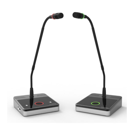
Page 24: Chairman Unit And Delegate Unit Operation
The colors of the LEDs of the microphone buttons and the LED ring of MIC show the condition of the microphone that connected to the discussion unit. MIC button color LED ring color Condition Red(on) Red(on) Microphone enabled White(off) Green(on) Request to speak 24 VISSONIC ELECTRONICS LIMITED...
Need help?
Do you have a question about the CLASSIC-D and is the answer not in the manual?
Questions and answers