Table of Contents

Related Manuals for Minuteman ED6200RM


Summary of Contents for Minuteman ED6200RM
- Page 1 ED6200RM Parallel Redundant ON-LINE SERIES User’s Manual Para Systems, Inc. 1455 LeMay Drive Carrollton, TX 75007 Phone: 1-972-446-7363 Fax: 1-972-446-9011 Internet: minutemanups.com UPS Sizing: sizemyups.com PN – 34000315 R5...
-
Page 2: Table Of Contents
Table of Contents 1 Important Safety Instructions........... 2 1.1 An Important Notice............... 2 1.2 Life Support Policy ..............3 1.3 FCC Notice................3 2 Product Introduction ..............4 2.1 System Overview..............4 2.2 General Characteristics............4 2.3 Symbols on the LCD Display Panel ........5 2.4 Controls and Indicators ............ -
Page 3: Important Safety Instructions
Servicing of the UPS system must be performed by Qualified Service copper wire and apply 22.1lb-in Torque force when connecting to terminal Personnel ONLY. MINUTEMAN accepts no liabilities and is not limited to: block. injury to the Service Personnel, or damages to; the UPS system, or the 1.1.14 CAUTION - To reduce the risk of electrical shock with the installation of this... -
Page 4: Product Introduction
2.2.8 This UPS system has the Independent Battery Bypass function. The 2 Product Introduction Independent Battery Bypass function allows the UPS system to provide a stable, regulated, transient-free pure sine wave AC output power even 2.1. System Overview when the batteries are weak or dead. This On-Line UPS protects computers, servers, internetworking, and 2.2.9 The battery management circuit analyses the battery discharging status to... - Page 5 DC BUS capacitor pre-charge abnormal after Er01 LINE UPS Abnormal Lock 50-seconds or Battery Fuse failure AC SCR or Battery SCR soft Start abnormal Er02 after 2-seconds UPS Flow Chart PFC (Boost) soft start abnormal after 30- Er03 seconds 4 Digits Measurement Display Er04 Inverter Failure Er05...
-
Page 6: Controls And Indicators
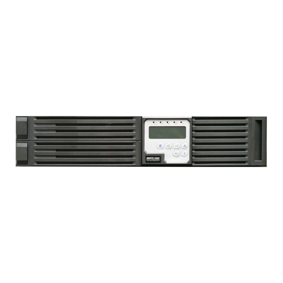
2.4. Controls and Indicators Er22 Bypass SCR or Output Fuse Fails 2.4.1 UPS module front panel Er23 Inverter Relay or SCR or Output Fuse Fails Er24 Bypass found when running on CVCF mode Er26 PFC Over-current The UPS must be operated in normal mode in Er27 parallel system Bypass Overload Time out and cut off output. -
Page 7: Rear Panels
Rear Panels C. L6-30R for UPS input connection. D. Maintenance Bypass Switch. 2.5.1 UPS module (ED6200RM) rear panel 2.5.3 Battery Pack module (EDBP6000RM) rear panel NOTE: The Output receptacle box is an option. Not all Battery Packs have the Output receptacle box. -
Page 8: Installation And Operation
3.2. 3 Installation and Operation Installation Placement (QUALIFIED SERVICE PERSONNEL ONLY) This UPS system is intended to be install in a temperature controlled Be sure to read the Installation Placement and all of the CAUTIONS and the environment that is free of conductive contaminants. Select a location, which WARNINGS before installing the UPS system. -
Page 9: Installation Of Castor Covers
3.4. 3.4.1.2 UPS, Isolation Transformer and Battery Pack Installation of the Caster Covers (QUALIFIED SERVICE PERSONNEL ONLY) Step1: Install the casters on the UPS; Isolation Transformer and Battery 3.4.1 Tower Installation Pack, and then connect UPS, Isolation Transformer and Battery Pack 3.4.1.1 UPS and Battery Pack (only) together. - Page 10 Step4 Install the Battery Pack to the Rails Step2 Install the rackmount brackets to the UPS, Isolation Transformer and Battery Pack Step5 Install the Rails in the 4-post Rack, and then install the Isolation Transformer to the Rails Step3 Install the Rails in the 4-post Rack Step6 Install the UPS in Rack...
-
Page 11: Wiring The Input And Output Connections
3.5. CAUTION - To reduce the risk of fire, connect the UPS Utility input to a branch Wiring the Input and Output Connections circuit with an over-current protection device in accordance with the National (Qualified Electrical Contractor Only) Electric Code, ANSI/NFPA 70. Use 60°C copper wire and apply 22.1lb-in of torque force when connecting to the terminal blocks. - Page 12 3.5.2.3.2 Connect the wires from the 208V/240V receptacle box (ED6-208RB) as 3.5.2.3.5 Configuration 1. follows (Output voltage 208V): Output: 208VAC 6KVA max load and two separate circuits of 120VAC 3KVA loads (3KVA max load per circuit). Total combined output load not to exceed 6KVA.
- Page 13 3.5.2.3.7 Configuration 3. 3.5.2.3.9 Configuration 5. Output: 240VAC 6KVA load and two separate circuits of 120VAC 3KVA loads Output: Two separate circuits of 120VAC 3KVA loads (3KVA max load per (3KVA max load per circuit). Total combined output load not to exceed 6KVA. circuit).
- Page 14 3.5.2.3.11 Configuration 7. 3.5.3.1 Application B: Output: 208VAC 6KVA load, 240VAC 6KVA load and two separate circuits of 1. Utility Input: 208/240VAC must be hardwired (see Section 3.5.1 for wiring). 120VAC 3KVA loads (3KVA max load per circuit). Total combined output load 2.
-
Page 15: Rj-45 Cables For The Maintenance Bypass Operation
3.5.4 Hardwiring the Input and Output wires to the terminal block on the UPS 3.5.4.4 Application E: module when using the UPS without the Isolation Transformer module. 1. Utility Input: 208/240VAC must be hardwired (see Section 3.5.4.1 for wiring). CAUTION - To reduce the risk of fire, connect the UPS Utility input to a branch 2. -
Page 16: Operation And Setup Instructions
3.7. 3.7.1.6 The UPS will perform another self-test and the LCD display will change Operation and Setup Instructions from drawing C to drawing D. During the self-test the UPS will switch to the Battery mode for approximately 4-seconds, then the LCD display will 3.7.1 Startup in the Normal Mode change from drawing D to drawing E1. - Page 17 3.7.1.7 The UPS has successfully passed the start-up procedure. The UPS will charge the batteries whenever the UPS is connected to an AC source and there is an acceptable AC voltage present. It is recommended that the UPS's batteries be charged for a minimum of 8-hours before use. However the UPS may be used immediately, but the “On-Battery”...
- Page 18 * It shows the input frequency from the Bypass Input. * It shows the Internal Temperature of the UPS System. 3.7.4 UPS Default Data and Special Function Features 3.7.4.1 Once the UPS has successfully started up, press the Special Function keypad to change the LCD display screen to drawing Q1.
- Page 19 * It shows the Self-test is “Disabled”. * It shows the Inverter Output Voltage setting. * It shows the Self-test is “Enabled”. * It shows the UPS is operated in the “Normal mode”. * It shows the UPS is operated in the “Eco mode”. * It shows the Bypass Voltage is adjusted to the lower limit.
- Page 20 3.7.5.3 Drawings S1 and S2 mean the bypass input window, can be changed to 184VAC~260VAC or 195VAC~260VAC. 3.7.5.4 Drawing T means the bypass frequency window of the Inverter Output can be changed to ±3Hz or ±1Hz. 3.7.5.5 Drawing U means the Inverter Output Voltage can be changed to 200VAC, 208VAC, 220VAC, 230VAC, or 240VAC.
-
Page 21: Communication Port, Epo Port And Option Cards
The maintenance of the UPS module must be done by Baud Rate 9600 bps QUALIFIED SERVICE PERSONNEL ONLY. MINUTEMAN accepts no Data Length 8 bits liabilities and is not limited to: injury to the Service Personnel, or damages... -
Page 22: Option Cards
4.2. EPO (Emergency Power Off) Port 5 Power Monitoring Software Connect one end of a two-wire cable to the EPO port and the other end of the The SentryPlus software that comes with the UPS is compatible with many two-wire cable to an EPO switch, and then short pin1 to pin2 for operating systems such as Windows NT/2000/XP/2003, Red Hat Linux, Fedora approximately 1.0-second to shutdown the UPS in the AC or the Battery Linux, SuSE Linux, and FreeBSD. -
Page 23: Troubleshooting Guide
6 Troubleshooting Guide 7 Replacing the Batteries (QUALIFIED SERVICE PERSONNEL ONLY) If the UPS malfunctions, check the followings: Please read all of the WARNINGS and CAUTIONS before attempting to a. Is the wiring of the input and the output correct? service the batteries. -
Page 24: Battery Replacement Procedure
7.1. 7.1.11 Cut the cable ties from the battery trays. Battery Replacement Procedure (QUALIFIED SERVICE PERSONNEL ONLY) This UPS system has Hot-swappable batteries. Hot-swappable batteries mean that the batteries can be replaced without powering down the whole UPS system. NOTE: If there is a power interruption while replacing the hot-swappable batteries, with the UPS system ON, the load will not be backed up. -
Page 25: Specifications
7.1.14 Gently remove the top part of the plastic battery tray. 8 Specifications 7.1.15 Disconnect the red battery wire from the battery terminal. 7.1.16 Disconnect the black battery wire from the battery terminal. ED6200RM MODEL 7.1.17 Disconnect the 3-battery jumper wires from the battery terminals. Topology Double Conversion On-Line, True Sine Wave 7.1.18 Remove the 4-defective batteries from the battery tray and set aside. -
Page 26: Obtaining Service
Sealed, Non-Spillable, Maintenance Free, most common problem. Call your dealer for assistance. If you cannot reach Valve Regulated, Lead Acid your dealer, or if they cannot resolve the problem call or fax MINUTEMAN Typical Recharge Time 8-hours from total discharge Technical Support at the following numbers;... -
Page 27: Limited Product Warranty
Para Systems. For equipment located outside of the United States and Canada, Para Systems only covers faulty parts. Para Systems products repaired or replaced Manufacturer’s Name: Para Systems, Inc. (MINUTEMAN UPS) pursuant to this warranty shall be warranted for the un-expired portion of the warranty applying to the original product.
Need help?
Do you have a question about the ED6200RM and is the answer not in the manual?
Questions and answers