Table of Contents
Advertisement
Quick Links
Advertisement
Table of Contents

Related Manuals for Advantech AIR-150


Summary of Contents for Advantech AIR-150
- Page 1 User Manual AIR-150 Fanless Edge Intelligence System...
- Page 2 This product contains a hard copy of the Chinese user manual for China CCC certifi- cation purposes. A PDF of the English user manual is included on the accompanying CD. Please disregard the hard copy Chinese user manual if the product is not sold and/or installed in China. AIR-150 User Manual...
- Page 3 No part of this manual may be reproduced, copied, translated or transmitted in any form or by any means without the prior written permission of Advantech Co., Ltd. Information provided in this manual is intended to be accurate and reliable. How- ever, Advantech Co., Ltd.
- Page 4 Because of Advantech’s high quality-control standards and rigorous testing, most of our customers never need to use our repair service. If an Advantech product is defec- tive, it will be repaired or replaced at no charge during the warranty period. For out- of-warranty repairs, you will be billed according to the cost of replacement materials, service time and freight.
- Page 5 Technical Support and Assistance Visit the Advantech website at http://support.advantech.com where you can find the latest information about the product. Contact your distributor, sales representative, or Advantech's customer service center for technical support if you need additional assistance. Please have the following information ready before you call: –...
- Page 6 70 dB (A). The equipment should only be installed in a restricted access area. DISCLAIMER: These instructions are provided according to IEC 704-1 specifi- cations. Advantech disclaims all responsibility for the accuracy of any state- ments contained herein. AIR-150 User Manual...
- Page 7 Les composants électroniques sensibles peuvent être endom- magés par des surtensions soudaines. Niveau de pression acoustique au poste de l'opérateur selon la norme CEI 704- 1: 1982 n'est pas supérieur à 70 dB (A). AIR-150 User Manual...
- Page 8 L'équipement ne doit être installé que dans une zone d'accès restreint. AVERTISSEMENT: Cet ensemble d'instructions est donné conformément à la norme CEI 704-1. Advantech décline toute responsabilité quant à l'exactitude des déclarations contenues dans ce. Packing List Before installation, check that the following items were included with the product: 1 x AIR-150 unit ...
-
Page 9: Table Of Contents
Table 1.1: Processor ..............3 Table 1.2: Chipset ............... 3 Table 1.3: Others................. 4 Mechanical Specifications................. 4 1.4.1 System Dimensions ..............4 Figure 1.1 AIR-150 Mechanical Dimensions ....... 4 1.4.2 Weight................... 4 Power Requirements................. 5 1.5.1 System Power................5 1.5.2 RTC Battery .................. - Page 10 2.5.1 M.2 B key/M-key/E-key Installation..........17 2.5.2 Memory Installation..............18 2.5.3 Slim SATA Installation ..............22 2.5.4 AIR-150 Wall Mount Installation ..........24 2.5.5 AIR-150 DIN-Rail Installation............25 Chapter BIOS Settings ........27 Introduction ..................... 28 Figure 3.1 ................. 28 Entering BIOS Setup................
- Page 11 Security ..................61 Figure 3.49.................. 61 Figure 3.50.................. 62 3.2.5 Boot..................... 63 Figure 3.51.................. 63 3.2.6 Save & Exit ................. 64 Figure 3.52.................. 64 3.2.7 NVMe RPMB KEY Migration............65 Figure 3.53.................. 65 3.2.8 MEBX..................65 Figure 3.54.................. 65 AIR-150 User Manual...
- Page 12 AIR-150 User Manual...
-
Page 13: Chapter 1 General Introduction
Chapter General Introduction This chapter gives background information on the AIR-150 series. -
Page 14: Introduction
Introduction AIR-150 fanless edge intelligence system is based on Intel 13th generation Core i5/i3 processor, built-in Iris Xe/UHD graphics chipsets, and added-on Hailo AI acceleration module, delivering 26 TOPS AI computing performance. Valued up with rich AI soft- ware toolkits to realize AI inferencing, AIR-150 also supports Advantech Edge AI SDK, which is suitable for AI-enabled applications in smart access control &... -
Page 15: Display
Supports SATA transfers to 300 Mbytes/sec. USB host interface with support for 3 x USB 3.2 and 1 x USB 2.0 USB Interface port All ports are High-Speed, Full-Speed, and Low-Speed capable BIOS AMI 256 Mbit Flash BIOS AIR-150 User Manual... -
Page 16: Mechanical Specifications
Supports Line Out and Mic In audio Connectors: 1 x Earphone jack Battery 1 x 3V/220 mAh battery with wire Mechanical Specifications 1.4.1 System Dimensions 156 x 112 x 60 mm Figure 1.1 AIR-150 Mechanical Dimensions 1.4.2 Weight 1.3 Kg AIR-150 User Manual... -
Page 17: Power Requirements
When the system is equipped with an Slim SATA: 30 G, IEC 60068-2-27, half sine, 11 ms duration 1.6.6 Safety Certification UL, CB, CCC, BSMI 1.6.7 EMC Certification CE/FCC Class B, Heavy Industry 61000-6-4, 61000-6-2, CCC, BSMI AIR-150 User Manual... - Page 18 AIR-150 User Manual...
-
Page 19: Chapter 2 Hardware Installation
Chapter Hardware Installation This chapter details instructions for installing AIR-150 hardware and external I/O. -
Page 20: Introduction
2.2.1 Jumper Description AIR-150 can be configured to satisfy specific application requirements by setting jumpers. A jumper is a metal bridge used to close an electric circuit. It consists of two metal pins and a small metal clip (often protected by a plastic cover) that slides over the pins to connect them. -
Page 21: Jumper Location
PIN HEADER 3x1P 2.0mm 180D(M) DIP 2000-13 WS Default Setting (1-2) Jumper Setting (2-3): Clear CMOS Table 2.3: CN22 Auto Power On Setting Part Number 1653004101 Description PIN HEADER 4x1P 2.0mm 180D(M) DIP 21N12050 Default Setting (1-2): ATX mode Jumper Setting (3-4): AT mode AIR-150 User Manual... -
Page 22: System I/O
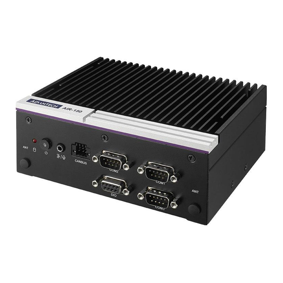
Table 2.5: Table 2.5: ERP1 ERP Power-saving Mode Part Number 1653000014 Description PIN HEADER 2x2P 2.00mm 180D(M) SMD 21N22050 Default Setting (1-2 short): Normal mode Jumper Setting (3-4 short): Enable ERP Power-saving mode System I/O Figure 2.2 Front View AIR-150 User Manual... -
Page 23: External I/O
Figure 2.3 Rear View External I/O 2.4.1 Power On/Off Button AIR-150 features a Power On/Off button with an LED indicators on the top side that show On status (Green LED). Figure 2.4 Power On/Off Button 2.4.2 Power Input Connector AIR-150 supports one 2-pin Phoenix terminal power input connector. Connect the positive and negative power cables to the terminals in the power distribution connec- tor correctly at the same time. -
Page 24: Ethernet Connector (Lan1/2)
2.4.3 Ethernet Connector (LAN1/2) AIR-150 is equipped with one Intel® I219-LM and one Intel® I226-LM Ethernet con- trollers that are fully compliant with IEEE 802.3u and 802.3bz 10/100/1000/2500 Mbps CSMA/CD standards and connected to LAN1 and LAN2. The Ethernet port provides a standard RJ45 jack connector with LED indicators on the front side to show its Active/Link status (Green LED) and Speed status (Orange/Yellow LED). -
Page 25: Usb 3.2 Gen1 Connector
2.4.4 USB 3.2 Gen1 Connector AIR-150 supports three USB 3.2 interfaces, which support Plug-and-Play functional- ity and hot swapping for up to 127 external devices. The USB interfaces comply with USB UHCI, Rev. 3.2. USB 3.2 connectors contain legacy pins to interface to USB 2.0 devices and a new set of pins for USB 3.2 connectivity. -
Page 26: Audio Connector
2.4.6 Audio Connector AIR-150 features one phone jack connectors that support stereo Line Out and Mic In audio ports. The audio chip is controlled by ALC888S and compliant with the Azalea standard. Figure 2.9 Audio Connector 2.4.7 COM Connector AIR-150 provides two 9-pin COM connector, which supports RS232/422/485 serial communication interface ports. -
Page 27: Hdmi Connector
2.4.8 HDMI Connector AIR-150 offers two integrated 19-pin receptacle connector HDMI 2.0b interfaces. The HDMI link supports resolutions up to 4096 x 2160 @ 60 Hz. Figure 2.11 HDMI Connector Table 2.10: HDMI Connector Pin Definition Signal Name HDMI_TX2+ HDMI_TX2-... -
Page 28: Canbus Port And Pin Definition
2.4.10 CANBUS Port and Pin Definition AIR-150 offers CANBUS port and pin definition as below. Figure 2.13 CANBUS Port Table 2.11: CANBUS Port and Pin Definition Signal Name CAN0_D- CAN1_D+ CAN0_D+ CAN1_D- 2.4.11 DIO Connector AIR-150 offers 9-bit DI/O and pin definition as below. -
Page 29: Installation
Installation 2.5.1 M.2 B key/M-key/E-key Installation Loosen the 7 screws affixing screws and remove the bottom cover. AIR-150 User Manual... -
Page 30: Memory Installation
Install the M.2 2280 M/ 2230 E key module. Install the M.2 E-Key 2230 (with round head screw). Install the M.2 M-Key 2280 module (with round head screw). 2.5.2 Memory Installation Loosen 4 screws affixing screws and remove the TOP cover. AIR-150 User Manual... - Page 31 Use two thermal pad from accessory box. If only one memory slot is used, the memory must be inserted into the NO.2 socket without using any thermal pad. PS: NO.1 socket is not recommended. AIR-150 User Manual...
- Page 32 If two memory (full slots) are used, two types of thermal pads are required (available in the Accessory bag). – First, use a larger thermal pad, attach to the back of the first memory (near the MB face), and plug in the NO.1 socket. AIR-150 User Manual...
- Page 33 – Finally, use smaller one for rest memory for NO.1 Slot AIR-150 User Manual...
-
Page 34: Slim Sata Installation
2.5.3 Slim SATA Installation Loosen the 7 screws affixing screws and remove the bottom cover. AIR-150 User Manual... - Page 35 Let Slim SATA to Fasten 4 screws onto bottom cover. Insert SATA Cable into MB. AIR-150 User Manual...
-
Page 36: Air-150 Wall Mount Installation
2.5.4 AIR-150 Wall Mount Installation AIR-150 default supports wall mount with the two wings on the bottom cover. Use 4x existed screw (with flat head screw) which already attached on side cover. AIR-150 User Manual... -
Page 37: Air-150 Din-Rail Installation
2.5.5 AIR-150 DIN-Rail Installation AIR-150 supports optional DIN-Rail. Use 7x 19300086506 Screw (with flat head screw), which is the same with wall Mount screw. (P.S. 3x screw in the accessory bag.) AIR-150 User Manual... - Page 38 AIR-150 User Manual...
-
Page 39: Chapter 3 Bios Settings
Chapter BIOS Settings This chapter details the BIOS con- figuration instructions. -
Page 40: Introduction
All configuration data is stored in battery-backed CMOS to ensure the setup information is retained when the power is turned off. This chapter describes the basic navigation of the AIR-150 BIOS setup screens. Figure 3.1 AIR-150 User Manual... -
Page 41: Entering Bios Setup
System Date using the <Arrow> keys. Enter new values via the keyboard. Press the <Tab> key or the <Arrow> keys to move between fields. The date must be entered in MM/DD/YY format, and the time must be entered in HH:MM:SS for- mat. AIR-150 User Manual... -
Page 42: Advanced Bios Setup
BIOS Setup items can be displayed by highlighting the item using the <Arrow> keys. 3.2.2.1 WWAN Configuration Figure 3.3 WWAN DEVICE When Disabled, Select the M.2 WWAN Device options to enable 4G - 7360/ 7560 (Intel), 5G - M80 (MediaTek) Modems. AIR-150 User Manual... - Page 43 3.2.2.2 CPU Configuration Figure 3.4 Figure 3.5 AIR-150 User Manual...
- Page 44 Displays the Efficient-core L1 Data Cache size. Displays the Efficient-core L1 Instruction Cache L1 Instruction Cache 64 KB size. L2 Cache 2048 KB X 2 Displays the Efficient-core L2 Cache size. L3 Cache 12 MB Displays the Efficient-core L3 Cache size. AIR-150 User Manual...
- Page 45 Displays the Performance-core L1 Instruction L1 Instruction Cache 32 KB x 2 Cache size. L2 Cache 1280 KB X 2 Displays the Performance-core L2 Cache size. L3 Cache 12 MB Displays the Performance-core L3 Cache size. AIR-150 User Manual...
- Page 46 3.2.2.3 Power & Performance Figure 3.8 Figure 3.9 CPU - Power Management Control View/Configure Turbo Options View/Configure Turbo Options. AIR-150 User Manual...
- Page 47 RC6(Render Standby) Check to enable render standby support. Maximum GT frequency Maximum GT frequency limited by the user. Disable Turbo GT frequency Enabled: Disables Turbo GT frequency. Disabled: GT frequency is not limited. AIR-150 User Manual...
- Page 48 3.2.2.4 PCH-FW Configuration Figure 3.10 Figure 3.11 AIR-150 User Manual...
- Page 49 Figure 3.12 Figure 3.13 ME State When Disabled ME will be put into ME Temporarily Disabled Mode. Manageability Features State Enable/Disable Intel(R) Manageability features. AIR-150 User Manual...
- Page 50 Hide Unconfigure ME confirmation prompt when attempting ME unconfigura- tion. MEBx OEM Debug Menu Enable Enable OEM debug menu in MEBx. Unconfigure ME Unconfigure ME with resetting MEBx password to default. 3.2.2.5 ACPI Settings Figure 3.14 AIR-150 User Manual...
- Page 51 Enables or Disables System ability to Hibernate (OS/S4 Sleep State). This option may not be effective with some operating systems. ACPI Sleep State Select the highest ACPI sleep state the system will enter when the SUSPEND button is pressed. AIR-150 User Manual...
- Page 52 3.2.2.6 iManager Configuration Figure 3.16 Figure 3.17 Serial Port 1 Configuration Serial Port Enable or Disable serial port. AIR-150 User Manual...
- Page 53 Watch Dog Timer function (Start before boot to OS and must stop by self). GPIO Configuration GPIO Control Enable Choose to control GPIO by EC or user override during POST stage. ACPI Report Method Control Select ACPI Reporting Method for EC Devices. AIR-150 User Manual...
- Page 54 3.2.2.7 Trusted Computing Figure 3.18 Figure 3.19 Security Device Support Enables or Disables BIOS support for security device. SHA256 PCR Bank AIR-150 User Manual...
- Page 55 Select to Tell O.S. to support PPI Spec Version 1.2 or 1.3. Note some HCK tests might not support 1.3. 3.2.2.8 S5 RTC Wake Settings Wake System from S5 Enable or disable System wake on alarm event. When enabled, System will wake on the hr::min::sec specified. Figure 3.20 AIR-150 User Manual...
- Page 56 Figure 3.21 3.2.2.9 Serial Port Console Redirection Console Redirection Console Redirection Enable or Disable. Figure 3.22 AIR-150 User Manual...
- Page 57 Figure 3.23 3.2.2.10 Intel TXT Information Figure 3.24 AIR-150 User Manual...
- Page 58 Figure 3.25 Provide Intel TXT information. 3.2.2.11 PCI Subsystem Settings Figure 3.26 AIR-150 User Manual...
- Page 59 Re-Sized BAR Support If system has Resizable BAR capable PCIe Devices, this option Enables or Dis- ables Resizable BAR Support. BME DMA Mitigation Re-enable Bus Master Attribute disabled during Pci enumeration for PCI Bridges after SMM Locked. AIR-150 User Manual...
- Page 60 3.2.2.12 USB Configuration Figure 3.28 Figure 3.29 AIR-150 User Manual...
- Page 61 The time-out value for Control, Bulk, and Interrupt transfers. Device Reset Timeout USB mass storage device Start Unit command time-out. Device Power-Up Delay Maximum time the device will take before it properly reports itself to the Host Controller. AIR-150 User Manual...
- Page 62 3.2.2.13 Network Stack Configuration Figure 3.31 Figure 3.32 Network Stack Enable/Disable UEFI network stack. AIR-150 User Manual...
- Page 63 3.2.2.14 CSM Configuration Figure 3.33 Figure 3.34 CSM Support Enable/Disable CSM support. AIR-150 User Manual...
- Page 64 System Agent (SA) Configuration Memory Configuration Display memory information. VT-d VT-d capability. Above 4GB MMIO BIOS assignment Enable/Disable above 4GB MemoryMappedIO BIOS assignment. This is enabled automatically when Aperture Size is set to 2048MB. Figure 3.35 AIR-150 User Manual...
- Page 65 Figure 3.36 Figure 3.37 Graphics Configuration Dvmt Total Gfx Mem 256MB. AIR-150 User Manual...
- Page 66 Select DVMT5.0 Total Graphic Memory size used by the Internal Graphics Device. RAV Enable Enabled VMD setup menu VMD Configuration settings PCI Express Configuration PCI Express Root Port 1 Select to enable or disable M.2 M Key. 3.2.3.2 PCH-IO Configuration Figure 3.38 AIR-150 User Manual...
- Page 67 Figure 3.39 Figure 3.40 PCI Express Configuration PCH PCIE Clock Gating Select to enable, PCH PCI Express Clock Gating Enable/Disable for all port. AIR-150 User Manual...
- Page 68 PCH PCIE Power Gating PCH PCI Express Power Gating Enable/Disable for all port. PCIe EQ settings This form contains options for controlling PCIe EQ process. Figure 3.41 Figure 3.42 AIR-150 User Manual...
- Page 69 Identify the SATA port is connected to Solid State Drive or Hard Disk Drive. Topology Identify the SATA Topology if it is Default or ISATA or Flex or DirectConnect or DITO Configuration Enable/Disable DITO Configuration. Figure 3.43 AIR-150 User Manual...
- Page 70 Select 'Enabled' if Overcurrent functionality is used. Enabling this will make xHCI controller consume the Overcurrent mapping data. USB Port Disable Override Selectively Enable/Disable the corresponding USB port from reporting a Device Connection to the controller. AIR-150 User Manual...
- Page 71 Figure 3.45 Figure 3.46 Security Configuration RTC Memory Lock Enable will lock bytes 38h-3Fh in the lower/upper 128-byte bank of RTC RAM. BIOS Lock AIR-150 User Manual...
- Page 72 Enable/Disable the PCH BIOS Lock Enable feature. Required to be enabled to ensure SMM protection of flash. Figure 3.47 Figure 3.48 HD Audio Configuration HD Audio AIR-150 User Manual...
- Page 73 Enable or disable boot option for LAN2 Controller. PCIE Wake Enable or disable PCIE to wake the system from S5. Restore AC Power Loss Specify what state to go to when power is re-applied after a power failure (G3 state). 3.2.4 Security Figure 3.49 AIR-150 User Manual...
- Page 74 Force System to User Mode. Install factory default Secure Boot key databases. Reset To Setup Mode Delete all Secure Boot key databases from NVRAM. Key Management Enables expert users to modify Secure Boot Policy variables without variable authentication. AIR-150 User Manual...
- Page 75 3.2.5 Boot Figure 3.51 Boot Setup Prompt Timeout Number of seconds to wait for setup activation key. Bootup NumLock State Select the keyboard NumLock state. Quiet Boot Enables or disables Quiet Boot option. AIR-150 User Manual...
- Page 76 Restore Defaults Restore/Load Default values for all the setup options. Save as User Defaults Save the changes done so far as User Defaults. Restore User Defaults Restore the User Defaults to all the setup options. AIR-150 User Manual...
- Page 77 3.2.7 NVMe RPMB KEY Migration Figure 3.53 3.2.8 MEBX Figure 3.54 AIR-150 User Manual...
- Page 78 No part of this publication may be reproduced in any form or by any means, such as electronically, by photocopying, recording, or otherwise, without prior written permission from the publisher. All brand and product names are trademarks or registered trademarks of their respective companies. © Advantech Co., Ltd. 2023...
Need help?
Do you have a question about the AIR-150 and is the answer not in the manual?
Questions and answers