
Related Manuals for Titan Fitness NEMESIS CFNTLTNR


Summary of Contents for Titan Fitness NEMESIS CFNTLTNR
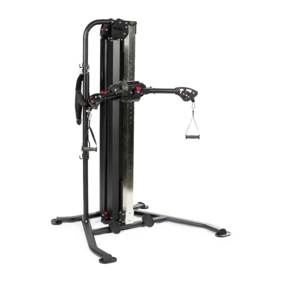
- Page 1 NEMESIS™ FUNCTIONAL TRAINER CFNTLTNR 401219 Operator’s Manual Read the Operator’s Manual entirely. When you see this symbol, the subsequent instructions and warnings are serious follow without exception. Your life and the lives of others depend on it!
- Page 2 COMPONENTS AS SHIPPED...
- Page 3 ASSEMBLY PARTS LIST DESCRIPTION BASE FRAME MAIN FRAME UPRIGHT FRAME SLIDING FRAME (10) TOP PULLEY FRAME (11) LOWER LIMITED FRAME (12) COUNTER WEIGHT (13) ADJUSTABLE TUBE (14) RIGHT COVER (15) LEFT COVER (16) FIXING PLATE (17) FRONT FIXING PLATE (18) LEFT LOGO PLATE 1 (19) LOGO PLATE 2...
- Page 4 ASSEMBLY INSTRUCTIONS STEP 1 Assemble the LOWER LIMITED FRAME (11) on BASE FRAME (1), using FIXING PLATE (16), FLAT WASHER Φ11*Φ20*2 (79), NUT M10(86), and HEX BOLT M10*30(70). TIGHTEN ALL THE BOLTS.
- Page 5 ASSEMBLY INSTRUCTIONS STEP 2 1. Connect MAIN FRAME (2) AND BASE FRAME (11), USING FLAT WASHER Φ11*Φ20*2 (79), SPRING WASHER Φ10 (83), and HEX BOLT M10*25 (71). 2. Connect UPRIGHT FRAME (3), MAIN FRAME (2) and BASE FRAME (11), using FLAT WASHER Φ11*Φ20*2 (79), SPRING WASHER Φ10 (83), NUT M10 (86), HEX BOLT M10*115 (62) and HEX BOLT M10*25 (71).
- Page 6 ASSEMBLY INSTRUCTIONS STEP 3 1. Install the LEFT LOGO PLATE (18) on MAIN FRAME (2), using FLAT WASHER Φ11*Φ20*2 (79), NUT M10 (86), and HEX BOLT M10*110 (63). 2. Connect TOP PERMANENT SEAT (21) and MAIN FRAME (2), using FLAT WASHER Φ6.6*Φ12*1.6 (81), SPRING WASHER Φ6 (85) and HEX BOLT M6*15 (74).
- Page 7 ASSEMBLY INSTRUCTIONS STEP 4 Install the RUBBER BUMPER (48), GUIDE ROD (24), WEIGHT PLATE (39), TOP WEIGHT STACK (40) on BASE FRAME (1) in turns, remove the bolts on GUIDE ROD BUSHING, then fixing the GUIDE ROD on REAR SUPPORT (2).
- Page 8 ASSEMBLY INSTRUCTIONS STEP 5 1. Connect RIGHT COVER (14) with logo at top to MAIN FRAME (2), using FLAT WASHER Φ8.4*Φ24*2 (80), SPRING WASHER Φ8 (84), RUBBER BUMPER (54) and HEX BOLT M8*65(76). 2. Connect LEFT COVER (14), TOP PERMANENT SEAT (21) and BASE PERMANENT SEAT (22), USING FLAT WASHER Φ6.6*Φ12*1.6 (81), SPRING WASHER Φ6 (85), and HEX BOLT M6*15 (74).
- Page 9 ASSEMBLY INSTRUCTIONS STEP 6 Insert the SLIDING FRAME (4) into the ADJUSTABLE TUBE (8), fixing by PIN.
- Page 10 ASSEMBLY INSTRUCTIONS STEP 7 1. Remove the pulley on MAIN FRAME (2), through the cable to the pulley, then reinstall the pulley. 2. Fix the ADJUSTABLE TUBE (13) on BASE FRAME (1), using FLAT WASHER Φ11*Φ20*2 (79), NUT M10 (86), and HEX BOLT M10*105(64). Install the FIXING PLATE (17) on ADJUSTABLE TUBE (13), USING FLAT WASHER Φ11*Φ20*2 (79), SPRING WASHER Φ10 (83), and HEX BOLT M10*105 (64).
- Page 11 ASSEMBLY INSTRUCTIONS Install the cables from ① to ⑬ in the sequence as shown. STEP 8...
- Page 12 ASSEMBLY INSTRUCTIONS STEP 9 Loosen the NUT M10 (86) and FLAT WASHER Φ11*Φ20*2 (79), install the LEFT LOGO PLATE (19) on MAIN FRAME (2), then reinstall the FLAT WASHER Φ11*Φ20*2 (79) and NUT M10(86). TIGHTEN THE NUTS.
- Page 13 ASSEMBLY INSTRUCTIONS STEP 10 Loosen the NUT M10 (86) and FLAT WASHER Φ11*Φ20*2 (79), connect the UPRIGHT FRAME (3), MAIN FRAME (2) AND TOP PULLEY FRAME (10), using FLAT WASHER Φ11*Φ20*2 (79) and NUT M10(86). TIGHTEN THE NUTS.
- Page 14 ASSEMBLY INSTRUCTIONS STEP 11 Fix the HANDLE (55) on PULLEY FRAME (7).
- Page 15 FULL PARTS LIST / EXPLODED VIEW...
- Page 16 PARTS DIAGRAM / EXPLODED VIEW DESCRIPTION DESCRIPTION (48) BASE FRAME STOPPER 80*45*50 (49) MAIN FRAME RUBBER BAFFLE (50) UPRIGHT FRAME END CAP 40*80*2.5 (51) SLIDING FRAME FLOOR MAT TAPERED RUBBER (52) ADJUSTABLE FRAME BUMPER (53) SWING ARM FRAME PLASTIC SLEEVE (54) PULLEY FRAME RUBBER BUMPER...
- Page 17 (24) (71) GUIDE ROD HEX BOLT M10*25 SPACER (25) (72) HEX BOLT M10*25 BUSHФ18*Ф10.2*44 (26) (73) Φ50 PULLEY HEX BOLT M6*20 (27) (74) ROLLER HEX BOLT M6*15 SPACER BUSH (28) (75) HEX BOLT M5*10 Ф12*Ф6*16 (29) (76) BEARING PULLEY HEX BOLT M8*65 (30) (77) CABLE Ф5*10690...
- Page 18 ACKNOWLEDGEMENT OF RISK AND RELEASE OF LIABILITY The use of any equipment, including this one, involves the potential risk of injury. Apart from any warranty claim that might be presented for a claimed defect in material or workmanship of the product, you accept and assume full responsibility for any and all injuries, damages (both economic and non-economic), and losses of any type, which may occur, and you fully and forever release and discharge Titan, its insurers, employees, officers, directors, associates, and agents from any and all claims, demands, damages,...
- Page 19 NEED HELP? CONTACT US FIRST. 1-888-410-1503 info@titan.fitness www.titan.fitness © 2021 Titan Brands...
Need help?
Do you have a question about the NEMESIS CFNTLTNR and is the answer not in the manual?
Questions and answers