Infineon TRAVEO T2G User Manual
Body high lite kit
Hide thumbs
Also See for TRAVEO T2G:
- Technical reference manual (1825 pages) ,
- Configuration and setup (97 pages) ,
- User manual (63 pages)
Table of Contents
Advertisement
Quick Links
KIT_T2G-B-H_LITE TRAVEO
T2G Body High Lite Kit
™
user guide
About this document
Scope and purpose
This document provides a comprehensive understanding of the TRAVEO
T2G Body High Lite (KIT_T2G-B-
™
H_LITE) low-cost Evaluation Kit. The kit is based on the TRAVEO
T2G CYT4BF device from the TRAVEO
Body
™
™
High family of microcontrollers.
This document serves to describe the features and functions of the TRAVEO
T2G Body High Lite kit. In addition,
™
it offers a detailed information on the available interfaces and guidelines for using the hardware interfaces. By
the end of this guide, users should have a thorough understanding of how to utilize the TRAVEO
T2G Body
™
High Lite kit and its various capabilities.
Intended audience
This document is designed for all customers who are interested in evaluating the capabilities of the TRAVEO
™
T2G Body High family CYT4BF device. Its main purpose is to offer a comprehensive guide that outlines the
various features of the device and how it can be used in a range of applications. Whether you are testing new
software or exploring different hardware designs, this document can provide valuable insights and guidance to
help you achieve your goals.
Evaluation board
The purpose of this board is to assist with the software evaluation during the design-in process. However, it is
important to note that while this board can be a helpful tool during the design process, it is not intended for use
in the final customer design. The PCB and auxiliary circuits are not optimized to meet the specific needs and
requirements of the end user. Instead, they are designed to provide a simplified and streamlined platform
exclusively for software evaluation purposes.
User guide
Please read the sections "Important notice" and "Warnings" at the end of this document
002-37237 Rev. *B
www.infineon.com
2024-06-14
Advertisement
Table of Contents

Subscribe to Our Youtube Channel
Related Manuals for Infineon TRAVEO T2G


Summary of Contents for Infineon TRAVEO T2G
-
Page 1: About This Document
Instead, they are designed to provide a simplified and streamlined platform exclusively for software evaluation purposes. User guide Please read the sections "Important notice" and "Warnings" at the end of this document 002-37237 Rev. *B www.infineon.com 2024-06-14... -
Page 2: Important Notice
Boards provided by Infineon Technologies. The design of the Evaluation Boards and Reference Boards has been tested by Infineon Technologies only as described in this document. The design is not qualified in terms of safety requirements, manufacturing and operation over the entire operating temperature range or lifetime. -
Page 3: Safety Precautions
KIT_T2G-B-H_LITE TRAVEO T2G Body High Lite Kit user guide ™ Safety precautions Safety precautions Note: Please note the following warnings regarding the hazards associated with development systems. Table 1 Safety precautions Caution: The evaluation or reference board contains parts and assemblies sensitive to electrostatic discharge (ESD). -
Page 4: Table Of Contents
KIT_T2G-B-H_LITE TRAVEO T2G Body High Lite Kit user guide ™ Table of contents Table of contents About this document ..............1 Important notice . - Page 5 KIT_T2G-B-H_LITE TRAVEO T2G Body High Lite Kit user guide ™ Table of contents 3.9.2 Arduino headers ..............35 3.9.3 mikroBUS headers .
-
Page 6: Getting Started
KIT_T2G-B-H_LITE TRAVEO T2G Body High Lite Kit user guide ™ 1 Getting started Getting started This section provides an overview of the TRAVEO T2G Body High Lite kit and offers step-by-step guidance on ™ how to set up and power up the kit. Additionally, it provides instructions on how to run the preprogrammed firmware and default jumper configuration to ensure a seamless experience. -
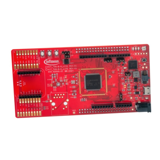
Page 7: Peripheral Details
KIT_T2G-B-H_LITE TRAVEO T2G Body High Lite Kit user guide ™ 1 Getting started 1.1.2 Peripheral details Figure 2 Peripheral and interfaces in the TRAVEO T2G B-H Lite kit front side ™ Figure 3 Peripheral and interfaces in the TRAVEO T2G B-H Lite kit back side ™... - Page 8 KIT_T2G-B-H_LITE TRAVEO T2G Body High Lite Kit user guide ™ 1 Getting started Table 2 Peripheral details Markup Schematic reference Peripheral Description designator TRAVEO T2G MCU TRAVEO T2G CYT4BF MCU ™ ™ device is used on the kit. Arudino header Powers the Arduino shields.
- Page 9 KIT_T2G-B-H_LITE TRAVEO T2G Body High Lite Kit user guide ™ 1 Getting started Table 2 (continued) Peripheral details Markup Schematic reference Peripheral Description designator KitProg3 mode select Use this button to switch button between various modes of operation of KitProg3. Note that this board supports only CMSIS-DAP BULK mode.
- Page 10 KIT_T2G-B-H_LITE TRAVEO T2G Body High Lite Kit user guide ™ 1 Getting started Table 2 (continued) Peripheral details Markup Schematic reference Peripheral Description designator Arduino header Bring out pins from TRAVEO T2G B-H MCU to ™ interface with Arduino shields. Some of these pins are multiplexed with onboard peripherals and are not connected to TRAVEO...
- Page 11 KIT_T2G-B-H_LITE TRAVEO T2G Body High Lite Kit user guide ™ 1 Getting started Table 2 (continued) Peripheral details Markup Schematic reference Peripheral Description designator mikroBUS header Optional header for mikroBUS Interface Crystal oscillator 25 MHz crystal for Ethernet transceiver Crystal oscillator 32.768 kHz watch crystal oscillator Ethernet PHY transceiver Ethernet PHY transceiver...
-
Page 12: Kit Content
KIT_T2G-B-H_LITE TRAVEO T2G Body High Lite Kit user guide ™ 1 Getting started Kit content This section provides a detailed list of the components that are included in the kit. Table 3 Kit contents Quantity Description Remarks KIT_T2G-B-H_LITE rev-01 TRAVEO T2G Body High Lite Kit ™... -
Page 13: Initial Jumper Configuration
KIT_T2G-B-H_LITE TRAVEO T2G Body High Lite Kit user guide ™ 1 Getting started Initial jumper configuration This section describes the default jumper configuration and location required for each module. Because a few interfaces are multiplexed, the default interface selection is mentioned in Table This initial configuration also helps to generate all the power supplies from the regulators and distribute them to safely power-up the lite kit. -
Page 14: Powering-Up The Kit Through Usb Micro-B
KIT_T2G-B-H_LITE TRAVEO T2G Body High Lite Kit user guide ™ 1 Getting started • The default powering option is to use a USB Micro-B cable, which can be connected to the USB Micro-B connector (J2). This option is capable of powering both the MCU and the on-board programmer/debugger KitProg3 •... -
Page 15: Powering-Up The Kit Through 12 V Dc Power Adapter
KIT_T2G-B-H_LITE TRAVEO T2G Body High Lite Kit user guide ™ 1 Getting started 1.4.2 Powering-up the kit through 12 V DC power adapter Ensure that the power is disconnected from the kit Short the jumper (J25) between position 2-3 Connect the 12 V DC power adapter to power jack (J1) Observe that the power LED is glowing green Input power supply selection jumper (J25) shorted between 2-3 Position... - Page 16 KIT_T2G-B-H_LITE TRAVEO T2G Body High Lite Kit user guide ™ 1 Getting started Test Results printed on the terminal Figure 8 Test logs printed on the serial terminal window (TeraTerm) User guide 002-37237 Rev. *B 2024-06-14...
-
Page 17: Programming The Kit
KIT_T2G-B-H_LITE TRAVEO T2G Body High Lite Kit user guide ™ 2 Programming the kit Programming the kit This section provides the instructions for installing the ModusToolbox IDE and how to program the Lite kit ™ using the ModusToolbox IDE. ™ If you are new to the TRAVEO T2G-B-H Lite kit and ModusToolbox software, see the... -
Page 18: Blink The Led
KIT_T2G-B-H_LITE TRAVEO T2G Body High Lite Kit user guide ™ 2 Programming the kit Quick Panel Menus & Toolbar Project Explorer Code Editor Console Outline Figure 9 ModusToolbox overview ™ Blink the LED The procedure for programming the kit and blinking the user LEDs is as follows: Ensure that the jumpers are configured according to the USB Micro-B powering option, and then connect the lite kit to the PC using the USB Micro-B cable Open ModusToolbox... - Page 19 KIT_T2G-B-H_LITE TRAVEO T2G Body High Lite Kit user guide ™ 2 Programming the kit Figure 10 Selecting the TRAVEO T2G B-H Lite kit BSP ™ After loading the code examples, click on the Getting Started and select the Hello World code example. Keep the default application name and then press the Create button Once the project is created successfully, go to the "Project Explorer"...
- Page 20 KIT_T2G-B-H_LITE TRAVEO T2G Body High Lite Kit user guide ™ 2 Programming the kit Figure 11 Building and then programming the LED Blinky code To view "Hello World" in the terminal window, make sure to open the serial terminal and connect it to the KitProg3 USB-UART COM port with baud rate of 115200.
-
Page 21: Functional Description
KIT_T2G-B-H_LITE TRAVEO T2G Body High Lite Kit user guide ™ 3 Functional description Functional description This section provides an overview of the major hardware blocks included in the TRAVEO T2G B-H Lite kit. ™ Understanding these blocks helps in understanding the capabilities and features of the kit and developing more effective designs and applications. -
Page 22: Power Supply
KIT_T2G-B-H_LITE TRAVEO T2G Body High Lite Kit user guide ™ 3 Functional description Table 5 (continued) Functionalities available on TRAVEO T2G B-H Lite kit ™ Functionality/feature Supported on TRAVEO T2G B-H Lite kit ™ Supported SDHC Not supported CRYPTO Supported Not supported Power supply This section provides a detailed information about the power supply and power flow in the TRAVEO... - Page 23 KIT_T2G-B-H_LITE TRAVEO T2G Body High Lite Kit user guide ™ 3 Functional description USB Micro-B 12 V DC USB Micro-B 12 V DC connector Power jack connector Power jack KP_VBUS KP_VBUS 5 V, 900 mA 12 V, 2 A 12 V, 2 A 5 V, 900 mA Power supply ‘OR’ing...
-
Page 24: Clock
KIT_T2G-B-H_LITE TRAVEO T2G Body High Lite Kit user guide ™ 3 Functional description Figure 14 shows the power supply to the TRAVEO T2G B-H MCU based on jumper selections. ™ VCC_5V0 VCC_3V3 1-2 shorted: 3.3 V to VDDD 1-2 shorted: 3.3 V to VDDIO 2-3 shorted: 5 V to VDDD 2-3 shorted: 5 V to VDDIO VDDD... -
Page 25: Reset
KIT_T2G-B-H_LITE TRAVEO T2G Body High Lite Kit user guide ™ 3 Functional description Watch crystal oscillator (Y1) Ethernet PHY External crystal oscillator (Y2) crystal (Y3) Figure 15 Location of various crystals in the Lite kit Reset This section describes to reset the TRAVEO T2G B-H Lite kit MCU using the reset button (SW2). -
Page 26: User Interfaces
KIT_T2G-B-H_LITE TRAVEO T2G Body High Lite Kit user guide ™ 3 Functional description Reset button (SW2) Figure 16 Location of the reset button in the Lite kit User interfaces The TRAVEO T2G B-H Lite kit provides several interfaces for user interaction such as three user LEDs, two push ™... -
Page 27: Potentiometer
KIT_T2G-B-H_LITE TRAVEO T2G Body High Lite Kit user guide ™ 3 Functional description Table 10 User push button User interface Reference designator CYT4BF MCU Pin number Port pin User push button 1 P5.3 User push button 2 P17.0 3.5.3 Potentiometer The TRAVEO T2G B-H Lite kit features a 10-kΩ... -
Page 28: Can Fd
KIT_T2G-B-H_LITE TRAVEO T2G Body High Lite Kit user guide ™ 3 Functional description 3.6.1 CAN FD The TRAVEO T2G B-H Lite kit provides a CAN FD transceiver (TLE9251VSJ), which supports data transmission ™ rates of up to 5 MBit/s. For connecting to other CAN FD nodes, the TRAVEO T2G B-H Lite kit features a 3-pin ™... -
Page 29: Dual-Quad Spi
KIT_T2G-B-H_LITE TRAVEO T2G Body High Lite Kit user guide ™ 3 Functional description 3.7.1 Dual-Quad SPI The TRAVEO T2G B-H Lite kit features two 512 Mb external Quad SPI NOR flash devices (S25HL512) that are ™ connected in dual QSPI mode. These devices provide fast, expandable memory for data and code, and can be a valuable tool for storing and retrieving data during development and testing. - Page 30 KIT_T2G-B-H_LITE TRAVEO T2G Body High Lite Kit user guide ™ 3 Functional description KP_UART_1_TX P0[0] KP_UART_1_R P0[1] PSoC™ 5LP TRAVEO™ T2G (KitProg3) B-H MCU Micro-B KP_UART_1_RTS P0[3] KP_UART_1_CTS P0[2] Legend TRAVEO™ T2G device PSoC™ 5LP device USB power Figure 20 UART connection between KitProg3 and TRAVEO T2G B-H MCU ™...
-
Page 31: Mipi-20 Cortex ® Debug Connector
KIT_T2G-B-H_LITE TRAVEO T2G Body High Lite Kit user guide ™ 3 Functional description PSoC™ 5LP KitProg3 mode Programming switch button header (J3) (SW1) USB Micro-B KitProg3 status PSoC™ 5LP connector (J2) KitProg3 (U4) LED (LED1) Figure 21 Location of KitProg3 and their interfaces ®... -
Page 32: General Purpose Io Headers
KIT_T2G-B-H_LITE TRAVEO T2G Body High Lite Kit user guide ™ 3 Functional description MIPI-20 Cortex® debug + ETM connector (J4) Figure 22 Other programming and debug interface available in the Lite kit General purpose IO headers The TRAVEO T2G B-H Lite kit provides a range of general-purpose I/O headers, which include two expansion ™... -
Page 33: Expansion Headers
KIT_T2G-B-H_LITE TRAVEO T2G Body High Lite Kit user guide ™ 3 Functional description KIT_T2G-B-H_LITE Board pinout details MISO MOSI GPIO GPIO MOSI MOSI MISO MISO (AD /SCL) C_SCL (AD /SDA) C_SDA IOREF/ V AREF/ V RST/XRES_L_MCU GND_ /GND D /SPI_CLK D /SPI_MISO GND_ /GND D /SPI_MOSI... - Page 34 KIT_T2G-B-H_LITE TRAVEO T2G Body High Lite Kit user guide ™ 3 Functional description Table 13 (continued) Expansion I/O header pin details Header pin Connected to MCU’s port pin Pin description X1.15 P0.3 P0_3 X1.16 P13.3 SPI_CS0 X1.17 P2.0 P2_0 X1.18 P13.2 SPI_CLK X1.19...
-
Page 35: Arduino Headers
KIT_T2G-B-H_LITE TRAVEO T2G Body High Lite Kit user guide ™ 3 Functional description Table 13 (continued) Expansion I/O header pin details Header pin Connected to MCU’s port pin Pin description X2.26 P11.0 P11_0 X2.27 P6.0 POT_AOUT X2.39 – X2.40 – 3.9.2 Arduino headers Table 14... -
Page 36: Mikrobus Headers
KIT_T2G-B-H_LITE TRAVEO T2G Body High Lite Kit user guide ™ 3 Functional description Table 14 (continued) Arduino header pin details Header pin Connected to MCU’s port pin Pin description J16 pins J16.1 P17.2 P17_2/D8 J16.2 P11.0 P11_0/D9 J16.3 P13.6 SPI_CS3/D10 J16.4 P13.1 SPI_MOSI/D11... -
Page 37: Shield2Go Connectors
KIT_T2G-B-H_LITE TRAVEO T2G Body High Lite Kit user guide ™ 3 Functional description 3.9.4 Shield2Go connectors Table 16 Shield2Go connector pin details Header pin Connected to MCU’s port pin Pin description J7 pins J7.1 – J7.2 P12.2 J7.3 P12.3 J7.4 P6.1 I2C_SDA J7.5... - Page 38 KIT_T2G-B-H_LITE TRAVEO T2G Body High Lite Kit user guide ™ 3 Functional description Table 16 (continued) Shield2Go connector pin details Header pin Connected to MCU’s port pin Pin description J19.14 P13.4 SPI_CS1 J19.15 P13.2 SPI_CLK J19.16 P13.1 SPI_MOSI J19.17 P13.0 SPI_MISO Shield2Go Arduino headers...
-
Page 39: Kit Design Documents
KIT_T2G-B-H_LITE TRAVEO T2G Body High Lite Kit user guide ™ 4 Kit design documents Kit design documents This section provides a detailed information on resources that can be used to understand the layout, design, and components of the TRAVEO T2G B-H Lite kit. These resources include layout images, schematics, ™... - Page 40 KIT_T2G-B-H_LITE TRAVEO T2G Body High Lite Kit user guide ™ 4 Kit design documents 3.3V Voltage Buck Regulator VIN_REG 0 OHM 0.1uF 22uF 22uF HDR 3 default 5V: (1-2) closed 12V : 2-3 VIN_REG VCC_3V3 HDR 2 3.3V, 3A KP_VBUS 2.2uH 5V_EN REG_SW 22uF...
- Page 41 KIT_T2G-B-H_LITE TRAVEO T2G Body High Lite Kit user guide ™ 4 Kit design documents Decoupling Capacitors PSoC 5LP based KitProg3 P5LP_VDD PSoC 5LP Power P5LP_VDD UART_1_CTS KP_VBUS P5LP_VDD P5LP2_0 P5LP2_1 0 OHM 0.1uF 0.1uF 0.1uF 0.1uF P5LP_VCCD P5LP2_2 P5LP2_3 P5LP2_4 KP_P0_4 P5LP_VCCD P5LP_VDD SAR Bypass...
- Page 42 KIT_T2G-B-H_LITE TRAVEO T2G Body High Lite Kit user guide ™ 4 Kit design documents T2G_MCU_Power Pass Transistor VCC_5V0 VCC_3V3 VDDD VDDD DRV_VOUT Power LED 0 OHM ZXT849KTC VCC_3V3 0 OHM HDR 3 EXT_PS_CTL0 VCCD 0.1 OHM 390 OHM LED2_A EXT_PS_CTL1 0 OHM LED2 10uF GREEN...
- Page 43 KIT_T2G-B-H_LITE TRAVEO T2G Body High Lite Kit user guide ™ 4 Kit design documents T2G-B-H-8M 176 MCU2 SPIHB_SEL1 P7_0/PWM1_M_4/PWM1_3_N/TC1_M_4_TR0/TC1_3_TR1/PWM0_1/SPIHB_SEL1/SDHC_CARD_IF_PWR_EN/SCB5_RX/SCB5_MISO/LIN4_RX/ADC[0]_16 SPIHB_DATA0 P7_1/PWM1_15/PWM1_M_4_N/TC1_15_TR0/TC1_M_4_TR1/SPIHB_DATA0/SDHC_CARD_DAT_3TO0_0/SCB5_TX/SCB5_SDA/SCB5_MOSI/LIN4_TX/ADC[0]_17 SPIHB_DATA1 P7_2/PWM1_M_5/PWM1_15_N/TC1_M_5_TR0/TC1_15_TR1/PWM0_1_N/SPIHB_DATA1/SDHC_CARD_DAT_3TO0_1/SCB5_RTS/SCB5_SCL/SCB5_CLK/LIN4_EN/ADC SPIHB_DATA2 P7_3/PWM1_16/PWM1_M_5_N/TC1_16_TR0/TC1_M_5_TR1/TC0_1_TR0/SPIHB_DATA2/SDHC_CARD_DAT_3TO0_2/SCB5_CTS/SCB5_SEL0/CAN0_4_TX/ADC[0]_1 SPIHB_DATA3 P7_4/PWM1_M_6/PWM1_16_N/TC1_M_6_TR0/TC1_16_TR1/TC0_1_TR1/SPIHB_DATA3/SDHC_CARD_DAT_3TO0_3/SCB5_SEL1/CAN0_4_RX/ADC[0]_20 SPIHB_DATA4 P7_5/PWM1_17/PWM1_M_6_N/TC1_17_TR0/TC1_M_6_TR1/PWM0_H_2/SPIHB_DATA4/SDHC_CARD_DAT_7TO4_0/LIN10_RX/SCB5_SEL2/ADC[0]_21 P7_6 P7_6/PWM1_M_7/PWM1_17_N/TC1_M_7_TR0/TC1_17_TR1/LIN10_TX/TRIG_IN[16]/ADC[0]_22 P7_7 P7_7/PWM1_18/PWM1_M_7_N/TC1_18_TR0/TC1_M_7_TR1/LIN10_EN/TRIG_IN[17]/ADC[0]_23 SPIHB_DATA5 P8_0/PWM1_19/PWM1_18_N/TC1_19_TR0/TC1_18_TR1/PWM0_H_2_N/SPIHB_DATA5/SDHC_CARD_DAT_7TO4_1/PWM1_H_8/LIN2_RX/CAN0_0_TX SPIHB_DATA6 P8_1/PWM1_20/PWM1_19_N/TC1_20_TR0/TC1_19_TR1/TC0_H_2_TR0/SPIHB_DATA6/SDHC_CARD_DAT_7TO4_2/PWM1_H_8_N/LIN2_TX/CAN0_0_RX/TRIG_IN[ SPIHB_DATA7 P8_2/PWM1_21/PWM1_20_N/TC1_21_TR0/TC1_20_TR1/TC0_H_2_TR1/SPIHB_DATA7/SDHC_CARD_DAT_7TO4_3/TC1_H_8_TR0/LIN2_EN/TRIG_IN[15]/ADC[0 P8_3/PWM1_22/PWM1_21_N/TC1_22_TR0/TC1_21_TR1/TC1_H_8_TR1/LIN16_RX/TRIG_DBG[0]/ADC[0]_26 P8_4/PWM1_23/PWM1_22_N/TC1_23_TR0/TC1_22_TR1/LIN16_TX/TRIG_DBG[1]/ADC[0]_27 P9_0/PWM1_24/PWM1_23_N/TC1_24_TR0/TC1_23_TR1/PWM1_H_9/LIN16_EN/ADC[0]_28 P9_1/PWM1_25/PWM1_24_N/TC1_25_TR0/TC1_24_TR1/PWM1_H_9_N/LIN12_RX/ADC[0]_29 P9_2/PWM1_26/PWM1_25_N/TC1_26_TR0/TC1_25_TR1/TC1_H_9_TR0/LIN12_TX/ADC[0]_30...
- Page 44 KIT_T2G-B-H_LITE TRAVEO T2G Body High Lite Kit user guide ™ 4 Kit design documents T2G-B-H-8M 176 MCU4 ETH_RXD0 P19_0/PWM1_M_3/PWM1_50_N/TC1_M_3_TR0/TC1_50_TR1/ETH0_RXD_0/TC1_H_0_TR0/SCB2_MISO/SCB2_RX/CAN1_3_TX/FAULT_OUT_2/ADC[2]_24 ETH_RXD1 P19_1/PWM1_26/PWM1_M_3_N/TC1_26_TR0/TC1_M_3_TR1/ETH0_RXD_1/TC1_H_0_TR1/SCB2_MOSI/SCB2_SDA/SCB2_TX/CAN1_3_RX/FAULT_OUT_3/ADC[2]_ P19_2/PWM1_27/PWM1_26_N/TC1_27_TR0/TC1_26_TR1/ETH0_RXD_2/TC1_H_1_TR0/SCB2_CLK/SCB2_SCL/SCB2_RTS/TRIG_IN[28]/ADC[2]_26 P19_3/PWM1_28/PWM1_27_N/TC1_28_TR0/TC1_27_TR1/ETH0_RXD_3/TC1_H_1_TR1/SCB2_SEL0/SCB2_CTS/TRIG_IN[29]/ADC[2]_27 P19_4/PWM1_29/PWM1_28_N/TC1_29_TR0/TC1_28_TR1/TC1_H_2_TR0/SCB2_SEL1/ADC[2]_28 P20_0/PWM1_30/PWM1_29_N/TC1_30_TR0/TC1_29_TR1/TC1_H_2_TR1/SCB2_SEL2/LIN5_RX/ADC[2]_29 P20_1/PWM1_49/PWM1_30_N/TC1_49_TR0/TC1_30_TR1/TC1_H_3_TR0/LIN5_TX/ADC[2]_30 P20_2/PWM1_48/PWM1_49_N/TC1_48_TR0/TC1_49_TR1/TC1_H_3_TR1/LIN5_EN/ADC[2]_31 P20_3/PWM1_47/PWM1_48_N/TC1_47_TR0/TC1_48_TR1/SCB1_RX/SCB1_MISO/CAN1_2_TX P20_4/PWM1_46/PWM1_47_N/TC1_46_TR0/TC1_47_TR1/SCB1_TX/SCB1_SDA/SCB1_MOSI/CAN1_2_RX P20_5/PWM1_45/PWM1_46_N/TC1_45_TR0/TC1_46_TR1/SCB1_RTS/SCB1_SCL/SCB1_CLK P20_6/PWM1_44/PWM1_45_N/TC1_44_TR0/TC1_45_TR1/SCB1_CTS/SCB1_SEL0/CAN1_4_TX P20_7/PWM1_43/PWM1_44_N/TC1_43_TR0/TC1_44_TR1/SCB1_SEL1/CAN1_4_RX WCO_IN P21_0/PWM1_42/PWM1_43_N/TC1_42_TR0/TC1_43_TR1/SCB1_SEL2/WCO_IN WCO_OUT P21_1/PWM1_41/PWM1_42_N/TC1_41_TR0/TC1_42_TR1/WCO_OUT ECO_IN P21_2/PWM1_40/PWM1_41_N/TC1_40_TR0/TC1_41_TR1/EXT_CLK/TRIG_DBG[1]/ECO_IN ECO_OUT P21_3/PWM1_39/PWM1_40_N/TC1_39_TR0/TC1_40_TR1/ECO_OUT P21_4/PWM1_38/PWM1_39_N/TC1_38_TR0/TC1_39_TR1/HIBERNATE_WAKEUP[0] XRES_L_MCU XRES ETH_RXCTL...
- Page 45 KIT_T2G-B-H_LITE TRAVEO T2G Body High Lite Kit user guide ™ 4 Kit design documents User LEDs VCC_3V3 22pF Y2 16MHz LED3 GREEN WCO_IN USER_LED1 0 OHM ECO_IN ECO_OUT LED4 GREEN 32.768kHz USER_LED2 0 OHM 22pF 18pF 18pF WCO_OUT LED5 GREEN USER_LED3 0 OHM VDDD VDDD...
- Page 46 KIT_T2G-B-H_LITE TRAVEO T2G Body High Lite Kit user guide ™ 4 Kit design documents CAN FD Transceiver VCC_5V0 VCC_5V0 VCC_3V3 120 OHM VCC_3V3 CANL CANL HDR 3 0.1uF 0.1uF 100pF CANH CANH CAN_TX HDR 2 CAN_RX TLE9251VSJ Quad SPI Flash Memory Section VCC_3V3 VCC_3V3 VCC_3V3...
- Page 47 KIT_T2G-B-H_LITE TRAVEO T2G Body High Lite Kit user guide ™ 4 Kit design documents VCC_3V3 0.1uF VCC_3V3 Ethernet PHY Interface ETH_PHY_INT VDDA3V3 INTR/PWRDN 0.1uF VDDIO GND2 ETH_PHY_RST RST_N ETH_MDIO MDIO ETH_MDC RJ45 Connector ETH_REFCLK 50MHzOut/LED2 ETH_PHY_LED0_R ETH_PHY_LED0 470 ohm LED0 ETH_TXEN TX_EN ETH_TXD0 TX_D0...
- Page 48 KIT_T2G-B-H_LITE TRAVEO T2G Body High Lite Kit user guide ™ 4 Kit design documents Shield2Go Connector VCC_3V3 VCC_5V0 ADC1_6 UART_RX ADC1_7 UART_TX P11_0 I2C_SDA RST/GPIO2 P17_1 I2C_SCL GPIO1 SPI_CS0 SPI_CLK SCLK P0_2 SPI_MOSI INT/GPIO3 MOSI P0_3 SPI_MISO PWM/GPIO4 MISO PLG-5-J_16 VCC_3V3 VCC_5V0 ADC1_8 UART_RX...
- Page 49 KIT_T2G-B-H_LITE TRAVEO T2G Body High Lite Kit user guide ™ 4 Kit design documents Arduino Headers VCC_5V0 VCC_5V0 VCC_3V3 HDR 10 I2C_SCL AD5/SCL I2C_SDA AD4/SDA AREF IOREF GND_3 XRES_L_MCU SPI_CLK SPI_MISO SPI_MOSI SPI_CS3 GND_1 P11_0 GND_2 P17_2 HDR 8 HDR 8 POT_AOUT P17_1 ADC1_6...
- Page 50 KIT_T2G-B-H_LITE TRAVEO T2G Body High Lite Kit user guide ™ 4 Kit design documents Accessories ACC6 ACC7 ACC8 ACC9 ACC10 SPC02SYAN SPC02SYAN SPC02SYAN SPC02SYAN SPC02SYAN Figure 40 Accessories User guide 002-37237 Rev. *B 2024-06-14...
-
Page 51: Assembly Drawings
KIT_T2G-B-H_LITE TRAVEO T2G Body High Lite Kit user guide ™ 4 Kit design documents Assembly drawings This section provides primary and secondary side assembly drawings for the TRAVEO T2G B-H Lite kit rev-01, ™ which can be used to understand the physical layout and assembly of the kit. PLACE_TOP PLACE_TOP Figure 41... - Page 52 KIT_T2G-B-H_LITE TRAVEO T2G Body High Lite Kit user guide ™ 4 Kit design documents PLACE_BOT PLACE_BOT Figure 42 Secondary side assembly of TRAVEO T2G B-H Lite kit rev-01 ™ User guide 002-37237 Rev. *B 2024-06-14...
-
Page 53: Layout Images
KIT_T2G-B-H_LITE TRAVEO T2G Body High Lite Kit user guide ™ 4 Kit design documents Layout images FAB1 This section provides primary and secondary side layout images of the TRAVEO T2G B-H Lite kit rev-01. ™ Figure 43 PCB fabrication FAB1 User guide 002-37237 Rev. - Page 54 KIT_T2G-B-H_LITE TRAVEO T2G Body High Lite Kit user guide ™ 4 Kit design documents L01_TOP L01_TOP Figure 44 Primary side layer 1 User guide 002-37237 Rev. *B 2024-06-14...
- Page 55 KIT_T2G-B-H_LITE TRAVEO T2G Body High Lite Kit user guide ™ 4 Kit design documents L02_GND L02_GND Figure 45 Ground layer 2 User guide 002-37237 Rev. *B 2024-06-14...
- Page 56 KIT_T2G-B-H_LITE TRAVEO T2G Body High Lite Kit user guide ™ 4 Kit design documents L03_SIG1 L03_SIG1 Figure 46 Signal layer 3 User guide 002-37237 Rev. *B 2024-06-14...
- Page 57 KIT_T2G-B-H_LITE TRAVEO T2G Body High Lite Kit user guide ™ 4 Kit design documents L04_SIG2 L04_SIG2 Figure 47 Signal layer 4 User guide 002-37237 Rev. *B 2024-06-14...
- Page 58 KIT_T2G-B-H_LITE TRAVEO T2G Body High Lite Kit user guide ™ 4 Kit design documents L05_PWR L05_PWR Figure 48 Power layer 5 L06_BOTTOM L06_BOTTOM Figure 49 Secondary side layer 6 User guide 002-37237 Rev. *B 2024-06-14...
-
Page 59: Bill Of Materials (Bom)
KIT_T2G-B-H_LITE TRAVEO T2G Body High Lite Kit user guide ™ 4 Kit design documents Bill of materials (BOM) This section provides the BOM for the TRAVEO T2G B-H Lite kit, which is a detailed list of all the components ™ and parts that are included in the kit (see Table 17). - Page 60 KIT_T2G-B-H_LITE TRAVEO T2G Body High Lite Kit user guide ™ 4 Kit design documents Table 17 (continued) KIT_T2G-B-H_LITE rev-01 bill of materials Quantity Reference Description Manufacturer Manufacturer Value Load designator name part number C48,C59 CAP CER 10UF Murata GRM188Z71A106K 10 µF –...
- Page 61 KIT_T2G-B-H_LITE TRAVEO T2G Body High Lite Kit user guide ™ 4 Kit design documents Table 17 (continued) KIT_T2G-B-H_LITE rev-01 bill of materials Quantity Reference Description Manufacturer Manufacturer Value Load designator name part number CONN RCPT Würth Elektronik 629105150521 629105150521 – USB2.0 Micro-B SMD R/A CONN header Samtec Inc.
- Page 62 KIT_T2G-B-H_LITE TRAVEO T2G Body High Lite Kit user guide ™ 4 Kit design documents Table 17 (continued) KIT_T2G-B-H_LITE rev-01 bill of materials Quantity Reference Description Manufacturer Manufacturer Value Load designator name part number FIXED IND 2.2 Abracon LLC ASPIAIG- 2.2 µH –...
- Page 63 4.2x3.2x2.5 mm 260 gf surface mount IC REG BCK BST Texas TPS630701RNMT TPS630701RNM – 5V 2A 15VQFN Instruments IC REG buck Infineon IR3883MTRPBF IR3883MTRPBF – adjustable 3 A Technologies 16PQFN IC MCU 32BIT Infineon CY8C5868LTI- CY8C5868LTI- – 256 KB flash...
- Page 64 IC PWR switch Vishay Siliconix SIP32402ADNP- SIP32402ADNP – N-CHAN 1:1 T1GE4 4TDFN T2G MCU IC 32- Infineon CYT4BF8CDDQ0AE CYT4BF8CDDQ0 – Bit Quad-Core Technologies AESGS 100 MHz, 350 MHz 8.1875 MB flash 176- TEQFP IC transceiver Infineon...
-
Page 65: Pinout Details
KIT_T2G-B-H_LITE TRAVEO T2G Body High Lite Kit user guide ™ 4 Kit design documents Table 17 (continued) KIT_T2G-B-H_LITE rev-01 bill of materials Quantity Reference Description Manufacturer Manufacturer Value Load designator name part number CONN header Molex 22284050 HDR 5 VERT 5 POS 2.54 mm J7,J19 Shield2go... - Page 66 KIT_T2G-B-H_LITE TRAVEO T2G Body High Lite Kit user guide ™ 4 Kit design documents Table 18 (continued) TRAVEO T2G B-H MCU pin details ™ Primary onboard function Secondary onboard function Connection details P6[5] SPIHB_SEL0 – Connected to CS of QSPI flash S25HL512TFAMHI010 P6[0] Potentiometer (POT)
- Page 67 KIT_T2G-B-H_LITE TRAVEO T2G Body High Lite Kit user guide ™ 4 Kit design documents Table 18 (continued) TRAVEO T2G B-H MCU pin details ™ Primary onboard function Secondary onboard function Connection details P14[1] UART_TX Arduino header (J14.2) This pin is connected to the UART TX Shield2Go connector (J7.11, J19.11) mikroBUS connector (J12.5)
- Page 68 KIT_T2G-B-H_LITE TRAVEO T2G Body High Lite Kit user guide ™ 4 Kit design documents Table 18 (continued) TRAVEO T2G B-H MCU pin details ™ Primary onboard function Secondary onboard function Connection details P21[2] ECO IN (Y2) – 16-MHz external crystal oscillator input P21[3] ECO OUT (Y2)
-
Page 69: Additional Information
KIT_T2G-B-H_LITE TRAVEO T2G Body High Lite Kit user guide ™ 5 Additional information Additional information This section describes the test points available and the advance features in this Lite kit. Test points Table 19 lists all the test points available in the Lite kit. Test point Description Connected to the flash reset line of both Quad SPI flash memory pin 3 (U9.3 and U10.3) - Page 70 KIT_T2G-B-H_LITE TRAVEO T2G Body High Lite Kit user guide ™ 5 Additional information Connect this TP1 to Ground via Jumper Figure 51 Reset the QSPI flash memories To reset the Ethernet PHY on the TRAVEO T2G B-H Lite kit, connect a jumper between the GND pin and ™...
-
Page 71: References
• Texas Ethernet PHY transceiver • Quad SPI NOR flash • TPS63070 2-V to 16-V buck-boost converter with 3.6 A switch current • Infineon IR3883MTRPBF datasheet User guides • KIT_T2G-B-H_LITE kit page • Eclipse IDE for ModusToolbox user guide ™... -
Page 72: Glossary
KIT_T2G-B-H_LITE TRAVEO T2G Body High Lite Kit user guide ™ Glossary Glossary alternating current analog-to-digital converter body high bill of materials controller area network CAN FD controller area network flexible data rate capacitor crystal oscillator central processing unit digital-to-analog converter direct current external crystal oscillator electrostatic discharge... - Page 73 KIT_T2G-B-H_LITE TRAVEO T2G Body High Lite Kit user guide ™ Glossary input output inter-integrated circuit inter-IC sound integrated circuit integrated development environment low dropout voltage regulator light-emitting diode Local Interconnect Network low power oscillator microcontroller unit personal computer PMIC power management integrated circuits potentiometer QSPI quad serial peripheral interface...
- Page 74 KIT_T2G-B-H_LITE TRAVEO T2G Body High Lite Kit user guide ™ Glossary SRAM static random-access memory Serial Wire Debug TRAVEO Generation ™ test point User guide 002-37237 Rev. *B 2024-06-14...
-
Page 75: Revision History
KIT_T2G-B-H_LITE TRAVEO T2G Body High Lite Kit user guide ™ Revision history Revision history Document Date Description of changes revision 2023-07-20 Initial release 2023-10-19 Added a note about schematics. Fixed pinout (Figure 3) and fixed schematics 2024-06-14 Updated the template Added content for the kit KIT_T2G-B-H_LITE rev. -
Page 76: Disclaimer
Infineon Technologies, Email: erratum@infineon.com Infineon Technologies’ products may not be used in any applications where a failure of the product or any consequences of the use thereof can reasonably be Document reference expected to result in personal injury.
Need help?
Do you have a question about the TRAVEO T2G and is the answer not in the manual?
Questions and answers