
Related Manuals for Infineon TC2X5


Summary of Contents for Infineon TC2X5
- Page 1 32-Bit Microcontroller Application Kit TC2X5 Hardware: APPLICATION KIT TC2X5 V2.0 Hardware Manual User’s Manual V 2.0 2013-05 M i c r o c o n t r o l l e r s...
- Page 2 Infineon Technologies components may be used in life-support devices or systems only with the express written approval of Infineon Technologies, if a failure of such components can reasonably be expected to cause the failure of that life-support device or system or to affect the safety or effectiveness of that device or system. Life support devices or systems are intended to be implanted in the human body or to support and/or maintain and sustain and/or protect human life.
- Page 3 32-Bit Microcontroller Application Kit TC2X5 Hardware: APPLICATION KIT TC2X5 V2.0 Hardware Manual User’s Manual V 2.0 2013-05 M i c r o c o n t r o l l e r s...
- Page 4 Trademarks ® TriCore is a trademark of Infineon Technologies AG. We Listen to Your Comments Any information within this document that you feel is wrong, unclear or missing at all? Your feedback will help us to continuously improve the quality of this document.
-
Page 5: Table Of Contents
Application Kit TC2X5 Hardware Manual Table of Contents Introduction ..........1-1 Application Kit Features . - Page 6 Application Kit TC2X5 Hardware Manual Schematic and Layout ........6-1 Schematic .
- Page 7 List of Figures Figure 2-1 Application Kit TC2X5 Block Schematic ..... . 2-3 Figure 2-2 Applcation Kit TC2X5 V2.0 Top Placement ....2-4 Figure 2-3 Applcation Kit TC2X5 V2.0 Bottom Placement .
-
Page 8: User's Manual
Application Kit TC2X5 Hardware Manual User’s Manual V 2.0, 2013-05... - Page 9 Application Kit TC2X5 Hardware Manual List of Tables Table 4-1 Power Signals ......... . 4-1 Table 4-2 Reset Signals .
- Page 10 Application Kit TC2X5 Hardware Manual User’s Manual V 2.0, 2013-05...
- Page 11 Application Kit TC2X5 Hardware Manual User’s Manual V 2.0, 2013-05...
-
Page 12: Introduction
This Application Kit Hardware Manual familiarizes you with the TriCore Evaluation Board and guides you through the initial configuration of the Application Kit. For detailed technical information about the TC2X5 (e.g. TC275, TC265, TC2D5) please refer to the User Manual of the device. - Page 13 Application Kit TC2X5 Hardware Manual Introduction User’s Manual V 2.0, 2013-05...
-
Page 14: Application Kit Features
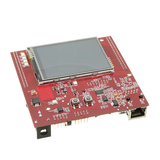
Hardware Manual Application Kit Features Application Kit Features Summary of Features – Infineon’s TC2X5 (e.g. TC275, TC265) Controller in LQFP-176 Package – LCD XGA Display 320x240 – SD card slot (mini SD) – High Speed CAN Transceivers – USB to UART bridge –... - Page 15 Application Kit TC2X5 Hardware Manual Application Kit Features – Touch screen controller ADS7843 – 4 general purpose LEDs – Reset switch – Start switch – Xilinx CPLD XC9572XL User’s Manual V 2.0, 2013-05...
-
Page 16: Block Diagram
OCDS1 converter with touch Micro TC265) miniWiggler TriCore QSPI1 I2C0 Transceiver ESR1 START WAKEUP POWER SUPPLY WITH Acoustic SUPERSONIC TLE7368-3E Beeper SHUTDOWN 4 LED’s (P33.8 up to P33.11) Figure 2-1 Application Kit TC2X5 Block Schematic User’s Manual V 2.0, 2013-05... -
Page 17: Placement
Application Kit TC2X5 Hardware Manual Application Kit Features Placement BU301 X205 D301 U301 D302 U203 X301 U102 L102 X103 U201 U101 APPLICATION KIT TC2X5 V2.0 INFINEON TECHNOLOGIES AG Figure 2-2 Applcation Kit TC2X5 V2.0 Top Placement User’s Manual V 2.0, 2013-05... -
Page 18: Figure 2-3 Applcation Kit Tc2X5 V2.0 Bottom Placement
Application Kit TC2X5 Hardware Manual Application Kit Features /PORST START D105 ESR0 D106 LCD201 P33.8 P33.9 P33.10 P33.11 Figure 2-3 Applcation Kit TC2X5 V2.0 Bottom Placement User’s Manual V 2.0, 2013-05... - Page 19 Application Kit TC2X5 Hardware Manual Application Kit Features User’s Manual V 2.0, 2013-05...
-
Page 20: Application Kit Information
Application Kit TC2X5 Hardware Manual Application Kit Information Application Kit Information Power Supply The microcontroller needs 3 different supply voltages. This voltages are generated internally via Infineons Next generation microcontroller supply TLE 7368-3E (+5V; +3,3V) and via the microcontroller itself (+1,3V). -
Page 21: Xga Display
Application Kit TC2X5 Hardware Manual Application Kit Information XGA Display The board has an XGA Display with a resolution of 320x240. The display has an ILI932x display controller. Please see the datasheet of the display controller for the register of the controller. -
Page 22: Touch Controller
Application Kit TC2X5 Hardware Manual Application Kit Information Bit 14 must be 0, this will be indicate a single access. Bit 13...Bit 7 is the 8 bit register number which will be read Bit 5...Bit 0 are dummy bits to setup the register number. -
Page 23: Clock
Application Kit TC2X5 Hardware Manual Application Kit Information – D109 up to D112 (blue) -> toogle LEDs connected to P33.8 ... P33.11 – D108 ESR0 (red) -> RESET LED indicate the reset state of the board – D107 +5V (green) -> +5V power supply indication –... -
Page 24: Beeper
The transducer is connected to pin P33.0 and needs a 2048Hz frequency. MultiCAN On the board is oneCAN transceiver connected to the MultiCAN on TC2X5 node 0. The transceiver is connected to an IDC10 plug. For the pinout of IDC10 plug see Figure 5-4. - Page 25 Application Kit TC2X5 Hardware Manual Application Kit Information f you connect a debug hardware make sure that the miniWiggler JDS (see “miniWiggler JDS” on Page 3-4) is not activ (ACTIV LED is off). If the ACTIV LED is on, then stop the active DAS Server ’UDAS’ and/or remove the USB connection to the PC.
-
Page 26: Signal Description
Application Kit TC2X5 Hardware Manual Signal Description Signal Description For more information about the signals please see the user manuals for TC2X5 and/or the schematics of the board. Table 4-1 Power Signals Short Name Description VCC_IN Supply Input (5,5V...50V(40V)) Input voltage of power supply device... -
Page 27: Table 4-4 Clock Signals
Application Kit TC2X5 Hardware Manual Signal Description Table 4-3 Interrupt Signals REQ3 / P10.3 External Trigger Input 3 REQ4 / P10.7 External Trigger Input 4 (Touch acttiv) REQ5 / P10.8 External Trigger Input 5 REQ8 / P33.7 External Trigger Input 8 REQ10 / P14.3... - Page 28 Application Kit TC2X5 Hardware Manual Signal Description Table 4-6 Peripheral Signals MTSR1 / P10.3 Master Transmit / Slave Receive SSC1 SLSO110 / P10.0 Slave Select Output 10 (SSC1) P20.8 CAN Transmitter Output 0 P20.7 CAN Receiver Input 0 P21.0 Ethernet MDC P21.1...
- Page 29 Application Kit TC2X5 Hardware Manual Signal Description User’s Manual V 2.0, 2013-05...
-
Page 30: Connector Pin Assignment
Application Kit TC2X5 Hardware Manual Connector Pin Assignment Connector Pin Assignment The Application Kit will be shipped with two 40 pin male (plug) connectors on top layer with a standard grid of 2,54mm. IO Connectors X102 X103 VCC_IN VEX T... -
Page 31: Power Connector Pinout
Application Kit TC2X5 Hardware Manual Connector Pin Assignment Power connector pinout + 5 ,5V … + 40 V G N D Figure 5-2 Power connector pinout USB connector pinout Figure 5-3 USB connector Pinout CAN connector pinout Figure 5-4 CAN connector pinout (IDC10) User’s Manual... -
Page 32: Lin Connector Pinout
Application Kit TC2X5 Hardware Manual Connector Pin Assignment LIN connector pinout Figure 5-5 LIN connector pinout (IDC10) OCDS connector pinout Figure 5-6 OCDS connector pinout (IDC16) User’s Manual V 2.0, 2013-05... -
Page 33: Ethernet Connector
Application Kit TC2X5 Hardware Manual Connector Pin Assignment Ethernet Connector Figure 5-7 Ethernet connector pinout (RJ45) DAP connector pinout Figure 5-8 DAP connector pinout (FTSH10) User’s Manual V 2.0, 2013-05... -
Page 34: Schematic And Layout
Application Kit TC2X5 Hardware Manual Schematic and Layout Schematic and Layout Schematic User’s Manual V 2.0, 2013-05... -
Page 35: Figure 6-1 Schematic - Project
Application Kit TC2X5 Hardware Manual Schematic and LayoutSchematic Figure 6-1 Schematic - Project User’s Manual V 2.0, 2013-05... -
Page 36: Figure 6-2 Schematic - Cpu And Power Supply
Application Kit TC2X5 Hardware Manual Schematic and Layout Figure 6-2 Schematic - CPU and Power Supply User’s Manual V 2.0, 2013-05... -
Page 37: Figure 6-3 Schematic - Peripherals
Application Kit TC2X5 Hardware Manual Schematic and LayoutSchematic Figure 6-3 Schematic - Peripherals User’s Manual V 2.0, 2013-05... -
Page 38: Figure 6-4 Schematic - Miniwiggler Jds And Ocds1
Application Kit TC2X5 Hardware Manual Schematic and Layout Figure 6-4 Schematic - miniWiggler JDS and OCDS1 User’s Manual V 2.0, 2013-05... -
Page 39: Layout
Application Kit TC2X5 Hardware Manual Schematic and LayoutLayout Layout BU301 R239 R247 R245 R246 CB305 R248 X205 R308 D301 CB221 R225 R222 U301 R226 D302 Q301 R318 R110 R328 U307 R315 CB317 Q302 R220 CB117 R327 CB314 C203 R319 CB315... -
Page 40: Figure 6-6 Component Plot Bottom Layer
Application Kit TC2X5 Hardware Manual Schematic and Layout U305 C211 C210 R240 R250 R243 CB306 R324 C301 U302 CB310 R242 CB220 CB312 R305 R321 CB309 R306 C306 C208 CB304 R326 U303 D105 R104 U304 R125 C204 R126 R105 CB208 CB215... -
Page 41: Layout With Dimensioning
CB112 R208 CB206 Q201 CB101 CB204 U202 CB203 CB102 CB103 R101 CB104 CB109 R124 CB110 CB106 Q101 CB105 R209 APPLICATION KIT TC2X5 V2.0 R210 INFINEON TECHNOLOGIES AG R120 R212 C105 L101 Figure 6-7 Dimensioning (mm) User’s Manual V 2.0, 2013-05... -
Page 42: Figure 6-8 Dimensioning (Mil)
CB112 R208 CB206 Q201 CB101 CB204 U202 CB203 CB102 CB103 R101 CB104 CB109 R124 CB110 CB106 Q101 CB105 R209 APPLICATION KIT TC2X5 V2.0 R210 INFINEON TECHNOLOGIES AG R120 R212 C105 L101 Figure 6-8 Dimensioning (mil) User’s Manual V 2.0, 2013-05... - Page 43 Application Kit TC2X5 Hardware Manual Keyword Index Micro SD card 3-3 miniWiggler JDS 3-4 ACTIV LED 3-4 MultiCAN 3-5 Beeper 3-5 OCDS connector pinout 5-3 OCDS1 3-5 Other peripherals 3-5 CAN connector pinout 5-2 Clock 3-4 Clock Signals 4-2 Peripheral Signals 4-2...
- Page 44 Application Kit TC2X5 Hardware Manual Write a display register 3-2 XGA Display 3-2 User’s Manual V 2.0, 2013-05...
- Page 45 . i n f i n e o n . c o m Published by Infineon Technologies AG...
Need help?
Do you have a question about the TC2X5 and is the answer not in the manual?
Questions and answers