
Related Manuals for DFI RPP171


Summary of Contents for DFI RPP171
- Page 1 RPP171_RPP173 Mini-ITX Industrial Motherboard User’s Manual © July 11, 2024 DFI Inc.
- Page 2 Copyright FCC and DOC Statement on Class B This publication contains information that is protected by copyright. No part of it may be repro- This equipment has been tested and found to comply with the limits for a Class B digital duced in any form or by any means or used to make any transformation/adaptation without the device, pursuant to Part 15 of the FCC rules.
-
Page 3: Table Of Contents
Specifications ......................... 6 ACPI Settings .........................37 Block Diagram ........................8 Network Stack Configuration..................37 Dimension ..........................8 DFI WDT Configuration ....................38 USB Power Control ......................39 Chapter 2 - Hardware Installation ....................9 Tls Auth Configuration ....................39 Board Layout ........................... 9 Chipset ..........................40 Installing the heat sink ......................10... - Page 4 About this Manual Static Electricity Precautions This manual can be downloaded from the website. It is quite easy to inadvertently damage your PC, system board, components or devices even before installing them in your system unit. Static electrical discharge can damage computer The manual is subject to change and update without notice, and may be based on editions that components without causing any signs of physical damage.
- Page 5 • Memory module • 1 RPP171/RPP173 Motherboard • Storage device such as a hard disk drive. • 1 COM port cable with bracket (Length: 250mm, 1 x COM ports) •...
-
Page 6: Chapter 1 - Introduction
1 x M.2 2242/3042/3052 B Key (PCIE Gen3x1, USB3.2 Gen2, USB2.0, selected by BIOS) 1 x M.2 2230 E Key (PCIE Gen3x1 and USB2.0, support Intel® CNVi) 1 x M.2 3042 A Key support DFI M2A-display module (opt. MOQ required) AUDIO... - Page 7 System Reset, Programmable via Software from 1 to 255 Seconds SECURITY dTPM (default) fTPM (option) POWER Type RPP171: Single 12VDC RPP173: Wide Range 9~36VDC Connector DC-in Jack Right Angle Connector (4-pin) (available upon request) Straightl Type Connector (4-pin) (available upon request)
-
Page 8: Block Diagram
Chapter 1 INTRODUCTION X Dimension X Block Diagram User's Manual | RPP171_RPP173... -
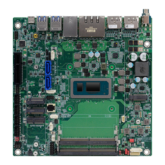
Page 9: Chapter 2 - Hardware Installation
Chapter 2 HARDWARE INSTALLATION Chapter 2 - Hardware Installation X Board Layout DC-in SATA0 DP/HDMI SATA1 DP/HDMI SATA Power LAN1 & LAN2 USB2.0 LAN3 USB3.2 Gen2 CPU Fan 10 9 USB3.2 Gen2 System Fan USB Type C RTC Battery Front Audio Front Panel PCIE Gen 4x4 Buzzer... -
Page 10: Installing The Heat Sink
Chapter 2 HARDWARE INSTALLATION X Installing the heat sink Installing the Heat Sink The CPU must be kept cool by using a heat sink, otherwise the CPU will overheat damaging both the CPU and system board. 1. Before you install the fan / heat sink, you must apply a thermal paste onto the top of the CPU. -
Page 11: Jumper Settings
Chapter 2 HARDWARE INSTALLATION X Jumper Settings Inverter Panel Power Select (DPJP2) Clear CMOS Data (SW1) 10 9 10 9 M.2 A Key M.2 A Key M.2 M Key M.2 M Key M.2 B Key M.2 B Key M.2 E Key M.2 E Key SO_DIMM1 SO_DIMM1... -
Page 12: Vcc Panel Power Select (Dpjp3)
Chapter 2 HARDWARE INSTALLATION Panel Backlight ON Level Select (DPJP4) VCC Panel Power Select (DPJP3) 10 9 10 9 M.2 A Key M.2 A Key M.2 M Key M.2 M Key M.2 B Key M.2 B Key M.2 E Key M.2 E Key SO_DIMM1 SO_DIMM1... -
Page 13: Com4 Dio & Com4 Select (Jp1)
Chapter 2 HARDWARE INSTALLATION COM3 Power Select (JP2) COM4 DIO & COM4 Select (JP1) 10 9 10 9 M.2 A Key M.2 A Key M.2 M Key M.2 M Key M.2 B Key M.2 B Key M.2 E Key M.2 E Key SO_DIMM1 SO_DIMM1 SO_DIMM2... -
Page 14: Pin Assignment
Chapter 2 HARDWARE INSTALLATION X Pin Assignment RTC Battery (J1) Case Open (J24) 10 9 10 9 M.2 A Key M.2 A Key M.2 M Key M.2 M Key M.2 B Key M.2 B Key M.2 E Key M.2 E Key SO_DIMM1 SO_DIMM1 SO_DIMM2... -
Page 15: System Fan (Cn25)
Chapter 2 HARDWARE INSTALLATION System Fan (CN25) CPU Fan (CN24) 10 9 10 9 M.2 A Key M.2 A Key M.2 M Key M.2 M Key M.2 B Key M.2 B Key M.2 E Key M.2 E Key SO_DIMM1 SO_DIMM1 SO_DIMM2 SO_DIMM2 Assignment... -
Page 16: Uart Header (Debug) (J21)
Chapter 2 HARDWARE INSTALLATION UART Header (Debug) (J21) SMBus (J16) 10 9 10 9 M.2 A Key M.2 A Key M.2 M Key M.2 M Key M.2 B Key M.2 B Key M.2 E Key M.2 E Key SO_DIMM1 SO_DIMM1 SO_DIMM2 SO_DIMM2 Assignment... -
Page 17: Sata Power (J18)
Chapter 2 HARDWARE INSTALLATION SATA POWER (J18) SATA POWER (J19) 10 9 10 9 M.2 A Key M.2 A Key M.2 M Key M.2 M Key M.2 B Key M.2 B Key M.2 E Key M.2 E Key SO_DIMM1 SO_DIMM1 SO_DIMM2 SO_DIMM2 Assignment... -
Page 18: Sata0 (J12)
Chapter 2 HARDWARE INSTALLATION SATA0 (J12) SATA1 (J13) 10 9 10 9 M.2 A Key M.2 A Key M.2 M Key M.2 M Key M.2 B Key M.2 B Key M.2 E Key M.2 E Key SO_DIMM1 SO_DIMM1 SO_DIMM2 SO_DIMM2 Assignment Assignment User's Manual | RPP171_RPP173... -
Page 19: Backlight Con (Dpj1)
Chapter 2 HARDWARE INSTALLATION Backlight CON (DPJ1) DIO (J15) 10 9 10 9 M.2 A Key M.2 A Key M.2 M Key M.2 M Key M.2 B Key M.2 B Key M.2 E Key M.2 E Key SO_DIMM1 SO_DIMM1 SO_DIMM2 SO_DIMM2 Assignment Assignment... -
Page 20: Front Audio (Auj1)
Chapter 2 HARDWARE INSTALLATION Front Audio (AUJ1) USB2.0 Pin Header (UBJ1) 10 9 10 9 10 9 M.2 A Key M.2 A Key M.2 M Key M.2 M Key M.2 B Key M.2 B Key M.2 E Key M.2 E Key SO_DIMM1 SO_DIMM1 SO_DIMM2... -
Page 21: Usb2.0 Pin Header (Ubj2)
Chapter 2 HARDWARE INSTALLATION USB2.0 Pin Header (UBJ2) COM3 Power Select (JP2) 10 9 10 9 M.2 A Key M.2 A Key M.2 M Key M.2 M Key M.2 B Key M.2 B Key M.2 E Key M.2 E Key SO_DIMM1 SO_DIMM1 SO_DIMM2... -
Page 22: Com1 (Tsj1)
Chapter 2 HARDWARE INSTALLATION COM2 RS232/RS422/RS485 (TSJ2) COM1 RS232/RS422/RS485 (TSJ1) 10 9 10 9 M.2 A Key M.2 A Key M.2 M Key M.2 M Key M.2 B Key M.2 B Key M.2 E Key M.2 E Key SO_DIMM1 SO_DIMM1 SO_DIMM2 SO_DIMM2 Assignment... -
Page 23: Com3 Rs232 (J5)
Chapter 2 HARDWARE INSTALLATION COM4 RS232 (J6) COM3 RS232 (J5) 10 9 10 9 M.2 A Key M.2 A Key M.2 M Key M.2 M Key M.2 B Key M.2 B Key M.2 E Key M.2 E Key SO_DIMM1 SO_DIMM1 SO_DIMM2 SO_DIMM2 Assignment... -
Page 24: Front Panel (J17)
Chapter 2 HARDWARE INSTALLATION COM4 DIO & COM4 Select (JP1) Front Panel (J17) 10 9 10 9 M.2 A Key M.2 A Key M.2 M Key M.2 M Key M.2 B Key M.2 B Key M.2 E Key M.2 E Key SO_DIMM1 SO_DIMM1 SO_DIMM2... -
Page 25: Expansion Slots
Chapter 2 HARDWARE INSTALLATION X Expansion Slots Installing the M.2 Module Before installing the M.2 module into the M.2 socket, please make sure that the following safety cautions are well-attended. 10 9 1. Make sure the PC and all other peripheral devices connected to it has been powered down. - Page 26 Chapter 2 HARDWARE INSTALLATION Please follow the steps below to install the card into the socket. Step 1: Insert the card into the socket at an angle while making sure the notch and key are perfectly aligned. Step 2: Press the end of the card far from the socket down until against the stand-off.
-
Page 27: Chapter 3 - Bios Settings
Chapter 3 BIOS SETTINGS Chapter 3 - BIOS Settings X Overview Legends The BIOS is a program that takes care of the basic level of communication between the CPU Keys Function and peripherals. It contains codes for various advanced features found in this system board. Right / Left arrow Move the highlight left or right to select a menu The BIOS allows you to configure the system and save the configuration in a battery-backed... -
Page 28: Main
Chapter 3 BIOS SETTINGS X Main X Advanced The Main menu is the first screen that you will see when you enter the BIOS Setup Utility. The Advanced menu allows you to configure your system for basic operation. Some entries are defaults required by the system board, while others, if enabled, will improve the performance of your system or let you set some features according to your preference. -
Page 29: Cpu Configuration
Chapter 3 BIOS SETTINGS Advanced Advanced CPU Configuration Power & Performance Intel (VMX) Virtualization Technology When this field is set to Enabled, the VMM can utilize the additional hardware capabilities pro- vided by Vanderpool Technology. Hyper-threading Enables this field for Windows XP and Linux which are optimized for Hyper-Threading technol- ogy. -
Page 30: Power & Performance ► Cpu- Power Management Control
Chapter 3 BIOS SETTINGS Advanced Advanced Power & Performance Power & Performance ► CPU- Power Management Control ► GT- Power Management Control RC6 (Render Standby) Turbo Mode Check to enable render standby support. Enable/Disable processor Turbo Mode (requires EMTTM enabled too). AUTO means enabled. C states Enable or disable CPU Power Management. -
Page 31: Pch-Fw Configuration
Chapter 3 BIOS SETTINGS Advanced Advanced Trusted Computing PCH-FW Configuration Security Device Support ME State This field is used to enable or disable BIOS support for the security device such as an TPM 2.0 to achieve hardware-level security via cryptographic keys. When this field is set to Disabled, ME will be put into ME Temporarily Disabled Mode. -
Page 32: It8786 Super Io Configuration
Chapter 3 BIOS SETTINGS Advanced Advanced IT8786 Super IO Configuration IT8786 Super IO Configuration ► Serial Port 1, 2 Configuration Serial Port Enable or disable serial port. User's Manual | RPP171_RPP173... -
Page 33: It8786 Super Io Configuration ► Serial Port 3, 4 Configuration
Chapter 3 BIOS SETTINGS Advanced Advanced IT8786 Super IO Configuration IT8786 HW Monitor ► Serial Port 3, 4 Configuration This section displays the system’s health information, i.e. voltage readings, CPU and system temperatures, and fan speed readings Smart Fan Function Smart Fan Function Setting. -
Page 34: It8786 Hw Monitor ► Smart Fan Function ► Cpu Fan Setting
Chapter 3 BIOS SETTINGS Advanced Advanced IT8786 HW Monitor IT8786 HW Monitor ► Smart FAN Function ► Smart FAN Function ► CPU FAN Setting IT8786 HW Monitor ► Smart FAN Function ► SYS_FAN Setting User's Manual | RPP171_RPP173... -
Page 35: Serial Port Console Redirection
Chapter 3 BIOS SETTINGS CPU / System Smart Fan Mode Advanced Smart Fan Mode Select Serial Port Console Redirection Fan off temperature limit Fan will be turned off when the temperature is lower than this limit. Fan start temperature limit Fan will start working when the temperature is higher than this limit. -
Page 36: Console Redirection Settings
Chapter 3 BIOS SETTINGS Advanced Serial Port Console Redirection ► Console Redirection Settings Configure the serial settings of the current COM port. Terminal Type Select terminal type: VT100, VT100+, VT-UTF8 or ANSI. Bits per second Select serial port transmission speed: 9600, 19200, 38400, 57600 or 115200. Data Bits Select data bits: 7 bits or 8 bits. -
Page 37: Serial Port Console Redirection Acpi Settings
Chapter 3 BIOS SETTINGS Advanced Advanced Network Stack Configuration ACPI Settings Wake system from S5 via RTC When Enabled, the system will automatically power up at a designated time every day. Once it’s switched to [Enabled], please set up the time of day — hour, minute, and second — for the system to wake up. -
Page 38: Dfi Wdt Configuration
Enable or disable UEFI network stack. The following fields will appear when this field is en- abled. DFI WDT Configuration Ipv4 PXE Support Enable or disable IPv4 PXE boot support. If disabled, IPv4 PXE boot support will not be avail- able. -
Page 39: Usb Power Control
Chapter 3 BIOS SETTINGS Advanced Advanced USB Power Control Tls Auth Configuration Server CA Configuration Server CA Configuration Press <Enter> to configure Server CA. 5_Dual: Support system wake up from S3/S4 by USB KB&MS 5V: No support system wake up from S3/S4 by USB KB&MS User's Manual | RPP171_RPP173... -
Page 40: Chipset
Chapter 3 BIOS SETTINGS X Chipset Chipset System Agent (SA) Configuration Please select a submenu and press Enter. The submenus are detailed in the following pages. Graphics Configuration Settings about graphic. VMD setup menu VMD Configuration Settings PCI Express Configuration : VT-d VT-d capability. -
Page 41: Pch-Io Configuration
Chapter 3 BIOS SETTINGS Chipset Chipset PCH-IO Configuration PCH-IO Configuration ► PCI Express Configuration PCI Express Configuration Select one of the PCI Express channels and press enter to configure the following settings. PCI Express Configuration Settings LAN1, LAN2, LAN3, M.2-E, M.2-B SATA Configuration Control the PCI Express Root Port. -
Page 42: Configuration► Sata Configuration
Chapter 3 BIOS SETTINGS Chipset Chipset PCH-IO Configuration PCH-IO Configuration ► HD Audio Configuration ► SATA Configuration SATA Controller(s) HD Audio This field is used to enable or disable the Serial ATA controller. Control the detection of the HD Audio device. SATA Speed •... -
Page 43: Security
Chapter 3 BIOS SETTINGS X Security Security Secure Boot Secure Boot Administrator Password The Secure Boot store a database of certificates in the firmware and only allows the OSes with Set the administrator password. To clear the password, input nothing and press enter when a new password is asked. -
Page 44: Boot
Chapter 3 BIOS SETTINGS X Boot X Save & Exit Save Changes and Reset Setup Prompt Timeout To save the changes, select this field and then press <Enter>. A dialog box will appear. Select Set the number of seconds to wait for the setup activation key. 65535 (0xFFFF) denotes indefi- Yes to reset the system after saving all changes made. -
Page 45: Updating The Bios
Chapter 3 BIOS SETTINGS X Updating the BIOS To update the BIOS, you will need the new BIOS file and a flash utility. Please contact techni- cal support or your sales representative for the files and specific instructions about how to update BIOS with the flash utility.
Need help?
Do you have a question about the RPP171 and is the answer not in the manual?
Questions and answers