Table of Contents
Advertisement
Copyright
Copyright © 2023 MITAC COMPUTING TECHNOLOGY CORPORATION. All rights
reserved. No part of this manual may be reproduced or translated without prior
written consent from MITAC COMPUTING TECHNOLOGY CORPORATION.
Trademark
All registered and unregistered trademarks and company names contained in this
manual are property of their respective owners including, but not limited to the
following.
®
TYAN
is a trademark of MITAC COMPUTING TECHNOLOGY CORPORATION.
®
AMD
is a trademark of AMD
Intel
®
is a trademark of Intel
AMI, AMI BIOS are trademarks of AMI Technologies.
®
Microsoft
, Windows
®
Nuvoton
is a trademark of Nuvoton Technology Corporation.
Notice
Information contained in this document is furnished by MITAC COMPUTING
TECHNOLOGY CORPORATION and has been reviewed for accuracy and reliability
prior to printing. MITAC assumes no liability whatsoever, and disclaims any express
or implied warranty, relating to sale and/or use of TYAN
or warranties relating to fitness for a particular purpose or merchantability. MITAC
retains the right to make changes to product descriptions and/or specifications at
any time, without notice. In no event will MITAC be held liable for any direct or
indirect, incidental or consequential damage, loss of use, loss of data or other
malady resulting from errors or inaccuracies of information contained in this
document.
S7136
Version 1.0b
®
Corporation.
®
Corporation.
®
are trademarks of Microsoft Corporation.
http://www.tyan.com
®
products including liability
1
Advertisement
Table of Contents

Related Manuals for TYAN S7136


Summary of Contents for TYAN S7136
- Page 1 TECHNOLOGY CORPORATION and has been reviewed for accuracy and reliability prior to printing. MITAC assumes no liability whatsoever, and disclaims any express ® or implied warranty, relating to sale and/or use of TYAN products including liability or warranties relating to fitness for a particular purpose or merchantability. MITAC retains the right to make changes to product descriptions and/or specifications at any time, without notice.
- Page 2 http://www.tyan.com...
-
Page 3: Table Of Contents
4.2 AMIBIOS Post Code (Aptio) ............170 Appendix I: How to recover UEFI BIOS ..........177 Appendix II: Installing the OCP3.0 Card ..........179 Appendix III: Installing the M.2 Card ............. 181 Appendix IV: Fan and Temp Sensors ........... 183 http://www.tyan.com... - Page 4 Glossary ....................189 Technical Support .................. 195 http://www.tyan.com...
-
Page 5: Before You Begin
2 x MCC CPU Carrier 1 x OCP3.0 Rail Kit 1 x OCP3.0 Screws 1 x S7136 Quick reference guide IMPORTANT NOTE: Sales sample may not come with the accessory listed above. Please contact your sales representative to help order accessory for your evaluation. - Page 6 http://www.tyan.com...
-
Page 7: Chapter 1: Instruction
32 and 64-bit computing, high-bandwidth memory design, and lightning-fast PCI-E bus implementation. The S7136 not only empowers you in today’s demanding IT environment but also offers a smooth path for future application upgradeability. All of these rich feature sets provides the S7136 with the power and flexibility to meet demanding requirements for today’s IT environments. - Page 8 (BMC) / 10/100/1000 Mb/s MAC interface Brand / ROM size AMI / 64MB Feature Hardware Monitor / FAN speed control BIOS automatic / Boot from USB device/PXE via LAN/Storage / Console Redirection / SMBIOS 3.3/PnP/Wake on LAN / ACPI http://www.tyan.com...
- Page 9 90%, non-condensing at 35° C RoHS RoHS 6/6 Compliant Operating OS supported list Please refer to our AVL support lists. System Motherboard (1) S7136 Motherboard Manual (1) Quick Installation Guide Cable SATA (2) SATA signal cables Package Others (1) OCP 3.0 Slide Rail Contains (1) M.2 Card Latch...
- Page 10 LAN/Storage / Console Redirection / SMBIOS 3.3/PnP/Wake on LAN / ACPI 6.0 / ACPI sleeping states S0, S5 Form Factor Proprietary Physical Dimension Board Dimension 14.18" x 12.16" (360.2 x 308.8mm) FCC (SDoC) Class A Regulation CE (DoC) Class A http://www.tyan.com...
-
Page 11: Software Specifications
(2) SATA signal cables Package Others (1) OCP 3.0 Slide Rail Contains (1) M.2 Card Latch (2) MCC Carrier (2) XCC Carrier 1.3 Software Specifications ® For OS (operation system) support, please check with TYAN support for latest information. http://www.tyan.com... - Page 12 NOTE http://www.tyan.com...
-
Page 13: Chapter 2: Board Installation
To avoid damaging the motherboard and associated components, do not use torque force greater than 5~7 kgf/cm (4.35 ~ 6.09 lb/in) on each mounting screw for motherboard installation. Do not apply power to the board if it has been damaged. http://www.tyan.com... -
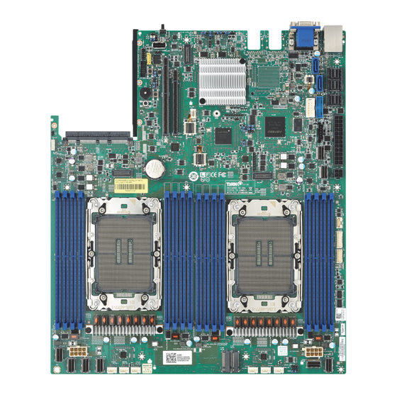
Page 14: Board Image
2.1 Board Image S7136GMRE This picture is representative of the latest board revision available at the time of publishing. The board you receive may not look exactly like the above picture. http://www.tyan.com... - Page 15 S7136GM2NRE-2T This picture is representative of the latest board revision available at the time of publishing. The board you receive may not look exactly like the above picture. http://www.tyan.com...
-
Page 16: Block Diagram
2.2 Block Diagram S7136 Block Diagram http://www.tyan.com... -
Page 17: Mainboard Mechanical Drawing
2.3 Mainboard Mechanical Drawing http://www.tyan.com... -
Page 18: Board Parts, Jumpers And Connectors
The board you receive may not look exactly like the above diagram. But for the DIMM number please refer to the above placement for memory installation. For the latest board revision, please visit our web site at http://www.tyan.com. http://www.tyan.com... - Page 19 43 FPB USB2.0 / USB3.2 Gen1 (CN8)) (USB3_FPIO1) 21 Vertical MCIO Connector (MCIO7 44 36-pin Vertical Mini-SAS HD Connector (CN7)) (SATA 3.0 signals) (SATA_0_3) 22 Vertical MCIO Connector (MCIO6 45 72-pin Vertical Mini-SAS HD Connector (CN6)) (SATA 3.0 signals) (SATA_0_7) http://www.tyan.com...
- Page 20 BMC Heartbeat LED (BMC_LED On board BMC IPMI Alert LED (IPMI_LED1) (D1_BMC)) Platform RESET LED (PLTRST_LED VIII Rear ID LED (ID_LED (ID_LED1)) (D83)) Jumper Legend OPEN - Jumper OFF Without jumper cover CLOSED - Jumper ON With jumper cover http://www.tyan.com...
- Page 21 FP_PW_LED_PW FP_ PWER (P3V3_AUX) FP_ID_LED_PW FP_PW_LED_GND FP_ID_LED_N HDD_LED_PW BMC_HW_FAULT_N HDD_ACT_LED_N BMC_SYS_FAULT_N FP_PWR_BTN_N LAN0_LED_P LAN0_LED_N FP_RST_BTN_JP_N FP_SMB_DAT FP_SMB_CLK FP_IDLED_BTN_N FP_INTRUSION_N SYS_AIR_INLET LAN1_LED_P FP_NMI_BTN_N LAN1_LED_N PSMI_HD1: PSMI Connector Signal SMB_CLK SMB_DAT PSU_SMBALERT_N P3V3 IPMB_HD1: 4-pin IPMB Connector Signal IPMB_DAT IPMB_CLK P3V3_AUX http://www.tyan.com...
- Page 22 J3: INTRUDER Header Signal INTRUDER# USB3_FPIO1: Front USB3.2 Gen1 Header Signal Signal USB3_N1_RX_FPB USB3_P1_RX_FPB USB3_N0_RX_FPB USB3_P0_RX_FPB USB3_N1_TX_C_FPB USB3_P1_TX_C_FPB USB3_N0_TX_C_FPB USB3_P0_TX_C_FPB USB2_FRONT2_R_DN USB2_FRONT2_R_DP USB2_FRONT_R_DN OC_N USB2_FRONT_R_DP ® J51: Intel VROC RAID KEY Connector (NVMe only) Signal Signal VCC3_AUX PCH_RAID KEY http://www.tyan.com...
- Page 23 P3V3_AUX HD_COM2: COM Port Header Signal Signal COM2_DCD COM2_DSR COM2_RXD COM2_RTS COM2_TXD COM2_CTS COM2_DTR COM2_NRI HDR_3 (CPU_HP_SMBUS): 7-pin NVMe Hot Plug Function Connector Signal P3V3_AUX HP0_SCK HP0_SDA CPU01_SMBALERT_N HP1_SCK HP1_SDA IDLED_BTN1: Rear IO ID LED Button Signal Signal FP_IDLED_BTN_N http://www.tyan.com...
- Page 24 Enter BIOS setup menu and load Default Settings. Then do a Save and Exit from setup. TYPEA_USB2: 4-pin Vertical USB2.0 Connector Signal USB2_N8 USB2_P8 SATA4: 7-pin Vertical SATA Connector PIN Define SATA8_TXP_C Connects to the Serial SATA8_TXN_C ATA ready drives via the Serial ATA cable. SATA8_RXN_C SATA8_RXP_C http://www.tyan.com...
- Page 25 RMII_RXD<1> RMII_TXD<0> RMII_RXD<0> OA10 OB10 CLK_100M_DN<3> OA11 OB11 CLK_100M_DN<2> CLK_100M_DP<3> OA12 OB12 CLK_100M_DP<2> OA13 OB13 RMII_CLK_IN OA14 OB14 RMII_CRS_DV P12V_EDGE_F P12V_EDGE_F P12V_EDGE_F P12V_EDGE_F P12V_EDGE_F P12V_EDGE_F SMB_SCL BIF_L<0> SMB_SDA BIF_L<1> SMB_RST_L BIF_L<2> PRSNTA1_N RST_PERST0_L RST_PERST1_L P3V3_EDGE_F PRSNTB2_L AUX_PWR_EN CLK_100M_DN<1> CLK_100M_DN<0> http://www.tyan.com...
- Page 26 PE_HOST_OCP_TX_DN<9> PE_HOST_OCP_RX_DP<9> PE_HOST_OCP_TX_DP<9> PE_HOST_OCP_RX_DN<8> PE_HOST_OCP_TX_DN<8> PE_HOST_OCP_RX_DP<8> PE_HOST_OCP_TX_DP<8> PRSNTB1_L PRSNTB0_L PE_HOST_OCP_RX_DN<7> PE_HOST_OCP_TX_DN<7> PE_HOST_OCP_RX_DP<7> PE_HOST_OCP_TX_DP<7> PE_HOST_OCP_RX_DN<6> PE_HOST_OCP_TX_DN<6> PE_HOST_OCP_RX_DP<6> PE_HOST_OCP_TX_DP<6> PE_HOST_OCP_RX_DN<5> PE_HOST_OCP_TX_DN<5> PE_HOST_OCP_RX_DP<5> PE_HOST_OCP_TX_DP<5> PE_HOST_OCP_RX_DN<4> PE_HOST_OCP_TX_DN<4> PE_HOST_OCP_RX_DP<4> PE_HOST_OCP_TX_DP<4> PE_HOST_OCP_RX_DN<3> PE_HOST_OCP_TX_DN<3> PE_HOST_OCP_RX_DP<3> PE_HOST_OCP_TX_DP<3> PE_HOST_OCP_RX_DN<2> PE_HOST_OCP_TX_DN<2> PE_HOST_OCP_RX_DP<2> PE_HOST_OCP_TX_DP<2> PE_HOST_OCP_RX_DN<1> PE_HOST_OCP_TX_DN<1> PE_HOST_OCP_RX_DP<1> PE_HOST_OCP_TX_DP<1> PE_HOST_OCP_RX_DN<0> PE_HOST_OCP_TX_DN<0> http://www.tyan.com...
- Page 27 M2_CN1, M2_CN2: M.2 Connector Signal Signal P3V3 P3V3 CPU0_PE3_M2_RX_R_DN<7> CPU0_PE3_M2_RX_R_DP<7> P3V3_AUX M2_LED_N CPU0_PE3_M2_TX_C_DN<7> P3V3 CPU0_PE3_M2_TX_C_DP<7> P3V3 P3V3 CPU0_PE3_M2_RX_R_DN<6> P3V3 CPU0_PE3_M2_RX_R_DP<6> CPU0_PE3_M2_TX_C_DN<6> CPU0_PE3_M2_TX_C_DP<6> CPU0_PE3_M2_RX_R_DN<5> CPU0_PE3_M2_RX_R_DP<5> CPU0_PE3_M2_TX_C_DN<5> CPU0_PE3_M2_TX_C_DP<5> M2_SMB_CLK CPU0_PE3_M2_RX_R_DN<4> M2_SMB_DAT CPU0_PE3_M2_RX_R_DP<4> M2_SMB_ALERT_N CPU0_PE3_M2_TX_C_DN<4> CPU0_PE3_M2_TX_C_DP<4> M2_PERST_N CLK_100M_M2_DN M2_WAKE_PCIE_N CLK_100M_M2_DP SATA_PCIE_M2_SEL P3V3 P3V3 P3V3 http://www.tyan.com...
- Page 28 CPU0_PE0_TX_DN<2> CPU0_PE0_RX_DP<3> CPU0_PE0_TX_DP<3> CPU0_PE0_RX_DN<3> CPU0_PE0_TX_DN<3> SATA_0_3: 36-pin Vertical Mini SAS HD Connector (SATA 3.0 signals) Signal Signal PCH_SSATA_0-3_A1 SGPIO_SATA2_CLOCK_R SGPIO_SATA2_LOAD_R SATA6G_DMI_RX_C_DP<5> SATA6G_DMI_RX_C_DP<4> SATA6G_DMI_RX_C_DN<5> SATA6G_DMI_RX_C_DN<4> SATA6G_DMI_RX_C_DP<7> SATA6G_DMI_RX_C_DP<6> SATA6G_DMI_RX_C_DN<7> SATA6G_DMI_RX_C_DN<6> SGPIO_SATA2_DATOUT_R SSGPIO_DI_0R SAS1_CTYPE SATA6G_DMI_TX_C_DP<5> SATA6G_DMI_TX_C_DP<4> SATA6G_DMI_TX_C_DN<5> SATA6G_DMI_TX_C_DN<4> SATA6G_DMI_TX_C_DP<7> SATA6G_DMI_TX_C_DP<6> SATA6G_DMI_TX_C_DN<7> SATA6G_DMI_TX_C_DN<6> http://www.tyan.com...
- Page 29 SATA1_RXN_C SATA0_RXN_C SATA3_RXP_C SATA2_RXP_C SATA3_RXN_C SATA2_RXN_C SGPIO_SATA0_DATOUT_R SGPIO_DI_0R SAS0_CTYPE SATA1_TXP_C SATA0_TXP_C SATA1_TXN_C SATA0_TXN_C SATA3_TXP_C SATA2_TXP_C SATA3_TXN_C SATA2_TXN_C NC_PCH_SATA_0-7_A1 SGPIO_SATA1_CLOCK_R SGPIO_SATA1_LOAD_R SATA5_RXP_C SATA4_RXP_C SATA5_RXN_C SATA4_RXN_C SATA7_RXP_C SATA6_RXP_C SATA7_RXN_C SATA6_RXN_C SGPIO_SATA1_DATOUT_R SGPIO_DI_1R SAS1_CTYPE SATA5_TXP_C SATA4_TXP_C SATA5_TXN_C SATA4_TXN_C SATA7_TXP_C SATA6_TXP_C SATA7_TXN_C SATA6_TXN_C http://www.tyan.com...
- Page 30 J2_PCH: PASSWORD CLEAR Jumper Pin1 Pin2 Pin3 FM_PASSWORD_CLEAR_N 1K-Pull down Pin1-2 closed: Normal Mode (Default) Pin2-3 closed: PASSWORD CLEAR J3_PCH: ME Recovery Jumper Pin1 Pin2 Pin3 10K-Pull hi FM_ME_RCVR_N 1K-Pull down Pin1-2 closed: Normal Mode (Default) Pin2-3 closed: Recover ME http://www.tyan.com...
- Page 31 Pin1-2 closed: Enable BMC Remote Debug Pin2-3 closed: Disable BMC Remote Debug (Default) J136: System Reset Jumper Pin1 Pin2 Pin3 FP_RST_BTN_N FP_RST_BTN_JP_N FP_BMC_RST_BTN_N Pin1-2 closed: System Reset (Default) Pin2-3 closed: BMC Reset 3PHD8: SMBUS Select Header (reserved) Pin1 Pin2 Pin3 CPU#_BMC_SMB_SEL http://www.tyan.com...
- Page 32 J14: System Buzzer Jumper Pin1 Pin2 Pin3 Pin4 VCC5_BZ BUZ_1 BUZ_2 Pin3-4 closed: Normal Mode (Default) Pin2-3 closed: Disable PC Beep Pin1-4 closed: Use the external speaker http://www.tyan.com...
-
Page 33: Led Definitions
HDD active blinking Signal P3V3_STBY State Description BMC_LED The LED shuts off when the Heartbeat (D1_BMC) BMC controller cannot be detected or properly initiated The LED blinks per second to Blinking Green indicate that the BMC controller is working normally http://www.tyan.com... - Page 34 Description (D83) Reset LED Platform Reset LED status is normal Platform Reset LED status is abnormal Signal P3V3 System SYS_PWROK State Description Power ok LED (D82) System Power LED status is normal System Power LED status is abnormal http://www.tyan.com...
-
Page 35: Installing The Processor And Heat Sink
Specifications on page 7. Check our website at http://www.tyan.com for latest processor support. NOTE: MITAC TYAN is not liable for damage as a result of operating an unsupported configuration. Processor Installation for Intel LGA4677 Socket Follow the steps below to install the processors and heat sinks. - Page 36 2. Align and install the processor on the carrier. Make sure the gold arrow is located in the correct direction. NOTE: When installing the processor, secure the front side (A) first, and following with the middle and rear sides (BC). 3. Remove the CPU cover. http://www.tyan.com...
- Page 37 Make also sure that the triangle edge of the carrier is aligned correctly with the triangle mark on the CPU socket. Then place the heatsink assembly onto the top of the CPU socket. 5. Press down on the retention clips to fix the heatsink assembly to the CPU socket. http://www.tyan.com...
- Page 38 Then apply new thermal grease before reinstalling the heatsink. NOTE: Always check with the manufacturer of the heat sink & processor to ensure that the thermal interface material is compatible with the processor and meets the manufacturer’s warranty requirements. http://www.tyan.com...
-
Page 39: Tips On Installing Motherboard In Chassis
Some chassis include plastic studs instead of metal. Although the plastic studs are usable, MITAC recommends using metal studs with screws that will fasten the motherboard more securely in place. Below is a chart detailing what the most common motherboard studs look like and how they should be installed. http://www.tyan.com... - Page 40 http://www.tyan.com...
-
Page 41: Installing The Memory
2.8 Installing the Memory Before installing memory, ensure that the memory you have is compatible with the http://www.tyan.com motherboard and processor. Check the TYAN Web site at for details of the type of memory recommended for your motherboard. Supports up to 128GB of ECC UDIMM DDR4 2666/2400MHz memory. - Page 42 √ √ P0_CHF_DIM0 √ √ √ √ √ P0_CHG_DIM0 √ √ √ √ √ √ P0_CHH_DIM0 √ √ √ √ 1 DIMM: P0_CHA_DIM0 or P0_CHE_DIM0 or P0_CHB_DIM0 or P0_CHF_DIM0. 2 DIMMs: P0_CHA_DIM0, P0_CHG_DIM0. or P0_CHC_DIM0, P0_CHE_DIM0. 4 DIMMs: P0_CHA_DIM0, P0_CHC_DIM0, P0_CHE_DIM0, P0_CHG_DIM0. 6 DIMMs: P0_CHA_DIM0, P0_CHC_DIM0, P0_CHD_DIM0, P0_ CHE_DIM0, P0_ CHF_DIM0, P0_ CHG_DIM0. or P0_CHA_DIM0, P0_ CHB_DIM0, P0_ CHC_DIM0,P0_ CHE_DIM0, P0_ CHG_DIM0, P0_ CHH_DIM0. or P0_CHB_DIM0, P0_ CHC_DIM0, P0_ CHD_DIM0,P0_ CHE_DIM0, P0_ CHF_DIM0, P0_ CHH_DIM0. or P0_CHA_DIM0, P0_ CHB_DIM0, P0_ CHD_DIM0,P0_ CHF_DIM0, P0_ CHG_DIM0, P0_ CHH_DIM0 8 DIMMs: P0_ CHA_DIM0, P0_ CHB_DIM0, P0_ CHC_DIM0, P0_ CHD_DIM0, P0_ CHE_DIM0, P0_ CHF_DIM0, P0_ CHG_DIM0, P0_ CHH_DIM0. http://www.tyan.com...
- Page 43 √ √ √ √ √ √ P1_CHD_DIM0 √ √ √ √ √ P1_CHE_DIM0 √ √ √ √ √ √ P1_CHF_DIM0 √ √ √ √ √ √ √ √ √ √ √ P1_CHG_DIM0 √ √ √ √ P1_CHH_DIM0 http://www.tyan.com...
- Page 44 Memory Installation Procedure Follow these instructions to install memory modules into the S7136. Unlock the clips as shown in the illustration. Insert the memory module firmly into the socket by gently pressing down until it sits flush with the socket.
-
Page 45: Attaching Drive Cables
2.9 Attaching Drive Cables Attaching Serial ATA Cables S7136 is equipped with fourteen (14) Serial ATA (SATA) channel. Connections for the drives are very simple. There is no need to set Master/Slave jumpers on SATA drives. If you are in need of SATA/SAS cables or power adapters please contact your place of purchase. -
Page 46: Installing Add-In Cards
Doing so allows air to circulate within the chassis more easily, thus improving cooling for all installed devices. NOTE: You must always unplug the power connector to the motherboard before performing system hardware changes to avoid damaging the board or expansion device. http://www.tyan.com... -
Page 47: Connecting External Devices
No Link Link Solid Green Linked at 10Mbps Active Blinking Green Link Solid Green Solid Green Linked at 100 Mbps Active Blinking Green Solid Green Link Solid Green Solid Amber Linked at 1 Gbps Active Blinking Green Solid Amber http://www.tyan.com... - Page 48 Active Blinking Yellow Link Solid Green Solid Yellow 1/2.5/5 Gbps Active Blinking Green Solid Yellow Link Solid Yellow Solid Yellow 10 Gbps Active Blinking Yellow Solid Yellow NOTE: Right LED (Speed) is a single-color LED, always showing yellow color. http://www.tyan.com...
-
Page 49: Installing The Power Supply
2.12 Installing the Power Supply There are four (4) power connectors on your S7136 motherboard. The S7136 supports EPS 12V power supply. NOTE: You must unplug the power supply before plugging the power cables to motherboard connectors. Warning: The mainboard supports up to... - Page 50 J55 (PWR4): 4-Pin Power Connector Signal Signal VCC12_CPU_OTHERS VCC12_CPU_OTHERS http://www.tyan.com...
-
Page 51: Installing Ocp3.0 Rail Kit
2. Install the OCP rail to the chassis. Then secure the rail using 1 screw. 2. Insert the server board into the chassis. 3. Use 9 screws (blue arrow) to secure the server board to the chassis. Then use another screw (red arrow) to secure the server board to OCP rail. http://www.tyan.com... -
Page 52: Finishing Up
In the rare circumstance that you have experienced difficulty, you can find help by asking your vendor for assistance. If they are not available for assistance, please find setup information and documentation online at our website or by calling your vendor’s support line. http://www.tyan.com... -
Page 53: Chapter 3: Bios Setup
The table below shows how to navigate in the setup program using the keyboard. Function Left/Right Arrow Keys Change from one menu to the next Up/Down Arrow Keys Move between selections Enter Open highlighted section PgUp/PgDn Keys Change pages Change options Exit http://www.tyan.com... - Page 54 The following pages provide the details of BIOS menu. Please be noticed that the BIOS menu are continually changing due to the BIOS updating. The BIOS menu provided are the most updated ones when this manual is written. Please visit TYAN’s website at http://www.tyan.com for the information of BIOS updating.
-
Page 55: Main Menu
System Date Set the Date. Use Tab to switch between Date elements. Default Ranges: Year: 2010~2079 Months: 1-12 Days: dependent on month Range of Years may vary. System Time Set the Time. Use Tab to switch between Time elements. http://www.tyan.com... -
Page 56: Advanced Menu
S5 RTC Wake Settings Enable system to wake from S5 using RTC alarm. Serial Port Console Redirection Serial Port Console Redirection. PCIe Device Configuration PCIe Device Configuration. USB Configuration USB Configuration Parameters. Onboard Device Configuration Onboard Device and Function Configuration. http://www.tyan.com... - Page 57 TIs Auth Configuration Press <Enter> to select TIs Auth Configuration. VLAN Configuration (MAC: XXXXXXXXXXXX) VLAN Configuration (MAC: XXXXXXXXXXXX) MAC: XXXXXXXXXXXX --- IPV4 Network Configuration Configure network parameters. (MAC: XXXXXXXXXXXX) MAC: XXXXXXXXXXXX --- IPV6 Network Configuration Configure IPV6 network parameters. (MAC: XXXXXXXXXXXX) http://www.tyan.com...
- Page 58 Enable Ipv4 HTTP Boot Support. If disabled IPV4 HTTP boot support will not be available. Disabled / Enabled Ipv6 PXE Support Enable Ipv6 PXE Boot Support. If disabled IPV6 PXE boot support will not be available. Disabled / Enabled http://www.tyan.com...
- Page 59 Disabled / Enabled PXE boot wait time Wait time to press ESC key to abort the PXE boot. Media detect count Number of times the presence of media will be checked. Use either +/- or numeric keys to set the value. http://www.tyan.com...
- Page 60 Select 0-23. For example enter 3 for 3am and 15 for 3pm. Wake up minute Select 0-59 for Minute. Wake up second Select 0-59 for Second. When Wake system from S5 is set to [Dynamic Time] Wake up Minute increase 1-5. http://www.tyan.com...
- Page 61 Console redirection enable or disable. Disabled / Enabled Legacy Console Redirection Settings Legacy Console redirection settings. Console Redirection Settings The settings specify how the host computer (which the user is using) will exchange data. Both computers should have the same or compatible settings. http://www.tyan.com...
- Page 62 1’s in the data bits is odd. Mark: parity bit is always 1. Space: parity bit is always 0. Mark and Space parity do not allow for error detection. None / Even / Odd / Mark / Space http://www.tyan.com...
- Page 63 On this mode enabled only text will be sent. This is to capture Terminal data. Disabled / Enabled Resolution 100x31 Enable or disable extended terminal resolution. Disabled / Enabled Putty KeyPad Select FunctionKey and KeyPad on Putty. VT100 / LINUX / XTERMR6 / SCO / ESCN / VT400 http://www.tyan.com...
- Page 64 1’s in the data bits is odd. Mark: parity bit is always 1. Space: parity bit is always 0. Mark and Space parity do not allow for error detection. None / Even / Odd / Mark / Space http://www.tyan.com...
- Page 65 On this mode enabled only text will be sent. This is to capture Terminal data. Disabled / Enabled Resolution 100x31 Enable or disable extended terminal resolution. Disabled / Enabled Putty KeyPad Select FunctionKey and KeyPad on Putty. VT100 / LINUX / XTERMR6 / SCO / ESCN / VT400 http://www.tyan.com...
- Page 66 When BootLoader is selected, then Legacy Console Redirection is disabled before booting to legacy OS, When Always Enable is selected, then Legacy Console Redirection is enabled for legacy OS. Default setting for this option is set to Always Enable. Always Enable / BootLoader http://www.tyan.com...
- Page 67 VT-UTF8 / VT100 / VT100+ / ANSI Bits per Second Select serial port transmission speed. The speed must be matched on the other side. Long or noisy lines may require lower speeds. 115200 / 9600 / 19200 / 57600 http://www.tyan.com...
- Page 68 ‘start’ signal can be sent to restart the flow. Hardware flow control uses two wires to send start/stop signal. None / Hardware RTS/CTS / Software Xon/Xoff Data Bits / Parity / Stop Bits Read only. http://www.tyan.com...
- Page 69 3.3.4 PCIe Device Configuration http://www.tyan.com...
- Page 70 Enable or Disable LAN2 Option ROM Enabled / Disabled PCIE#1~5 Option ROM Enable or Disable Option ROM execution for selected Slot. Enabled / Disabled OCP3.0 Option ROM Enable or Disable Option ROM execution for selected Slot. Enabled / Disabled http://www.tyan.com...
- Page 71 USB Mass Storage Driver Support Enable/Disable USB Mass Storage Driver Support. Disabled / Enabled Port 60/64 Emulation Enables I/O Port 60h/64h emulation support. This should be enabled for the complete USB keyboard legacy support for non-USB aware OSes. Disabled / Enabled http://www.tyan.com...
- Page 72 Hub descriptor. Auto / Manual NOTE: Device power up delay in seconds is available when Device power-up delay is set to [Manual]. Device power-up delay in seconds Delay range is 1…40 seconds, in one second increments. http://www.tyan.com...
- Page 73 Primary Display Select active Video type. Onboard / External NMI Function Enable or Disable NMI function. Enabled / Disabled Chassis Intrusion Detection Enabled: When a chassis open event is detected, the BIOS will display the event. Enabled / Disabled http://www.tyan.com...
- Page 74 3.3.7 Super IO Configuration Serial Port 1 Configuration Set Parameters of Serial Port 1 (COMA). http://www.tyan.com...
- Page 75 3.3.7.1 Serial Port 1 Configuration Serial Port Enable or disable Serial Port (COM). Enabled / Disabled Device Settings Read only. Change Settings Select an optimal setting for Super IO Device. Auto / IO=3F8h; IRQ=4; / IO=2F8h, IRQ=4; / IO=3E8h, IRQ=4; / IO=2E8h, IRQ=4; http://www.tyan.com...
- Page 76 Nvidia GeForce / Quardro GPU and any VGA card. PWM Minimal Duty Cycle PWM Minimal Duty Cycle (%).This item is available when Fan Speed Control is set to [Manual]. BMC Alert Beep Enable/Disable BMC Alert Beep. On / Off PMBus support PMBus Support. Enabled / Disabled http://www.tyan.com...
- Page 77 3.3.8.1 Sensor Data Register Monitoring http://www.tyan.com...
- Page 78 NOTE: SDR can not be modified. Read only. http://www.tyan.com...
- Page 79 Enables or Disables 64bit capable Devices to be Decoded in Above 4G Address Space (Only if System Supports 64 bit PCI Decoding). Enabled / Disabled SR-IOV Support If system has SR-IOV capable PCIe Devices, this option Enables or Disables Single Root IO Virtualization Support. Enabled / Disabled http://www.tyan.com...
- Page 80 PCI Express Settings Max Payload Set Maximum Payload of PCI Express Device or allow System BIOS to select the value. Auto / 128 Bytes / 256 Bytes / 512 Bytes / 1024 Bytes / 2048 Bytes / 4096 Bytes http://www.tyan.com...
- Page 81 3.3.10 NVMe Configuration This page shows the Device Name you installed. Press Enter to read the device information. If no NVME device is installed, it shows no NVME device is found. Read only. http://www.tyan.com...
- Page 82 3.3.11 Trusted Computing Security Device Support Enables or Disables BIOS support for security device. O.S. will not show Security Device. TCG EFI protocol and INT1A interface will not be available. Enabled / Disabled http://www.tyan.com...
- Page 83 Network Controls the execution of UEFI and Legacy PXE OpROM UEFI / Legacy Storage Controls the execution of UEFI and Legacy Storage OpROM UEFI / Legacy Video Controls the execution of UEFI and Legacy Video OpROM UEFI / Legacy http://www.tyan.com...
- Page 84 Other PCI devices Determines OpRom execution policy for devices other than network, storage, or video UEFI / Legacy http://www.tyan.com...
- Page 85 3.3.13 Redfish Host Interface Settings Redfish Enable/Disable AMI Redfish. Enabled / Disabled BMC Redfish Version / BIOS Redfish Version Read only. IP Address Enter IP address. IP Mask Address Enter IP Mask address. IP Port Enter IP Port. http://www.tyan.com...
- Page 86 3.3.14 TIs Auth Configuration Server CA Configuration Press <Enter> to configure Server CA. Client Cert Configuration Press <Enter> to configure Client Cert. http://www.tyan.com...
- Page 87 3.3.14.1 Server CA Configuration Enroll Cert Press <Enter> to enroll cert. Delete Cert Press <Enter> to delete cert. http://www.tyan.com...
- Page 88 3.3.14.1.1 Enroll Cert Enroll Cert Using File Enroll Cert Using File. Cert GUID Input digit character in 11111111-2222-3333-4444-1234567890ab format. Commit Changes and Exit Commit Changes and Exit. Discard Changes and Exit Discard Changes and Exit. http://www.tyan.com...
- Page 89 3.3.14.1.2 Delete Cert FE9C6606-8B49-44A3-8B6B-DEA3A0E032 GUID for CERT. Disabled / Enabled http://www.tyan.com...
- Page 90 Please follow the instructions to initiate the iSCSI function. Step 1. Select Advanced CSM Configuration Network [UEFI]. Step 2. Select Advanced Network Stack Configuration Network Stack [Enabled] Step 3. Save changes and reboot. Host iSCSI Configuration Host iSCSI Configuration http://www.tyan.com...
- Page 91 Add an Attempt. Delete Attempts Delete one or more attempts. Change Attempt Order Change the order of Attempts using +/- keys. Use arrow keys to select the attempt then press +/- to move the attempt up/down in the attempt order list. http://www.tyan.com...
- Page 92 3.3.15.1.1 Add an Attempt The screen shows the network protocols installed. If no network protocols are installed, the screen displays the message “Necessary network protocols are not available to retrieve….” http://www.tyan.com...
- Page 93 3.3.15.1.2 Delete Attempts Commit Changes and Exit Commit Changes and Exit. Discard Changes and Exit Discard Changes and Exit. http://www.tyan.com...
- Page 94 3.3.15.1.3 Change Attempt Order Commit Changes and Exit Commit Changes and Exit. Discard Changes and Exit Discard Changes and Exit. http://www.tyan.com...
- Page 95 3.3.16 VLAN Configuration (MAC:xxxxxxxxxxxx) Enter Configuration Menu Press ENTER to enter configuration menu for VLAN configuration. http://www.tyan.com...
- Page 96 3.3.16.1 Enter Configuration Menu VLAN ID VLAN ID of new VLAN or existing VLAN, valid value is 0~4094. Priority 802.1Q Priority, valid value is 0~7. Add VLAN Create a new VLAN or update existing VLAN. Remove VLAN Remove selected VLANs. http://www.tyan.com...
- Page 97 3.3.17 MAC:xxxxxxxxxxxx - IPv4 Network Configuration Configured Indicate whether network address configured successfully or not. Disabled / Enabled Save Changes and Exit Save Changes and Exit. http://www.tyan.com...
- Page 98 3.3.18 MAC:xxxxxxxxxxxx - IPv6 Network Configuration Enter Configuration Menu Press ENTER to enter configuration menu for IPv6 configuration. http://www.tyan.com...
- Page 99 Duplicate Address Detection on a tentative address. A value of zero indicates that Duplicate Address Detection is not performed. Policy Automatic or manual. Automatic / Manual NOTE: The Advanced Configuration submenu is available when Policy is set to [Manual]. Save Changes and Exit Save Changes and Exit. http://www.tyan.com...
-
Page 100: Cpu
Displays and provides option to change the Uncore Settings. Memory Configuration Displays and provides option to change the Memory Settings. IIO Configuration Displays and provides option to change the IIO Settings. Advanced Power Management Configuration Displays and provides option to change the Power Management Settings. http://www.tyan.com... - Page 101 =MLC Streamer Prefetcher (MSR 1A4h Bit [0]). Disabled / Enabled Adjacent Cache Prefetch =MLC Spatial Prefetcher (MSR 1A4h Bit [1]). Disabled / Enabled Extended APIC Enabled/Disabled extended APIC support. NOTE: This will enable VT-d automatically if x2APIC is enabled. Disabled / Enabled http://www.tyan.com...
- Page 102 AES-NI Enabled/Disabled AES-NI support. Disabled / Enabled http://www.tyan.com...
- Page 103 3.4.2 Common RefCode Configuration Numa Enable or Disable Non uniform Memory Access (NUMA). Disabled / Enabled http://www.tyan.com...
- Page 104 3.4.3 Uncore Configuration Uncore General Configuration Displays and provides option to change the Uncore General Settings. http://www.tyan.com...
- Page 105 Allows for selecting the UPI Link Frequency. 9.6GT/s / 10.4GT/s / 11.2GT/s / Auto / Use Per Link Setting Link L0p Enable Enable --- Set the c_l0p_en, Disable --- Reset it, Auto --- Auto decides based on Si Compatibility. Disabled / Enable / Auto http://www.tyan.com...
- Page 106 Selects the allocation size used to assign mmioh resources. Total mmioh space can be up to 32xgranularity. Per stack mmioh resource assignments are multiples of the granularity where 1 unit per stack is the default allocation. 1G / 4G / 16G / 64G / 256G / 1024G http://www.tyan.com...
- Page 107 3.4.3.1.1 Uncore Status Read only http://www.tyan.com...
- Page 108 (limited by processor support). Do not select Reserved. Auto / 4000 / 4400 / 4800 Memory Topology Displays memory topology with Dimm population information. Memory RAS Configuration Displays and provides option to change the Memory RAS Settings. http://www.tyan.com...
- Page 109 3.4.4.1 Memory Topology Read only. http://www.tyan.com...
- Page 110 Enabling any type of Mirror Mode will disable XPT Prefetch. Disabled / Full Mirror Mode / Partial Mirror Mode Mirror TAD0 Enable Mirror on entire memory for TAD0. Enabled / Disabled Correctable Error Threshold Correctable Error Threshold (0x01 – 0x7fff) used for sparing, tagging, and leaky bucket. http://www.tyan.com...
- Page 111 Patrol Scrub Enable/Disable Patrol Scrub. Disabled / Enabled Patrol Scrub Interval Selects the number of hours (1-24) required to complete full scrub. A value of zero means auto! http://www.tyan.com...
- Page 112 This option can disable ASPM support in all PCIe root ports. Disabled / Per-Port PCIe Max Read Request Size This option can set requested Max Read Request Size in PCI hierarchy. ‘Default’ kepps hardware default. Auto / 128B / 256B / 512B / 1024B / 2048B / 4096B http://www.tyan.com...
- Page 113 Auto / x4x4x4x4 / x4x4_x8 / x_x8x4x4 / x_x8x_x8 / x_x_x_x_x16 IOU3 (IIO PCIe Port 4) Selects PCIe port Bifurcation for selected slot(s).Fort Format: xDxCxBxA The port can further be x2x2. Auto / x4x4x4x4 / x4x4_x8 / x_x8x4x4 / x_x8x_x8 / x_x_x_x_x16 http://www.tyan.com...
- Page 114 IOU4 (IIO PCIe Port 5) Selects PCIe port Bifurcation for selected slot(s).Fort Format: xDxCxBxA The port can further be x2x2. Auto / x4x4x4x4 / x4x4_x8 / x_x8x4x4 / x_x8x_x8 / x_x_x_x_x16 Port 1A/1C/1E/1G/2A/2E/3A/4A/4C/4E/4G/5A/5C/5E/5G Settings related to PCI Express Ports (0/1A/1B/1C/1D/2A/2B/2C/2D/3A/3B/3C/3D/4A/4B/4C/4D/5A/5B/5C/5D). http://www.tyan.com...
- Page 115 This option specifies if the link is considered Hot Plug capable. Disabled / Enabled Link Speed Choose Link Speed for this PCIe port. Auto / Gen1 (2.5 GT/s) / Gen2 (5 GT/s) / Gen3 (8 GT/s) / Gen4 (16 GT/s) http://www.tyan.com...
- Page 116 PCI-E Port L1 Exit Latency The length of time this port requires to complete transition from L1 to L0. <1uS / 1uS-2uS / 2uS-4uS / 4uS-8uS / 8uS-16uS / 16uS-32uS / 32uS- 64uS / >64uS MCTP Enabled/Disabled MCTP. No / Yes http://www.tyan.com...
- Page 117 Auto / x4x4x4x4 / x4x4_x8 / x_x8x4x4 / x_x8x_x8 / x_x_x_x_x16 IOU3 (IIO PCIe Port 4) Selects PCIe port Bifurcation for selected slot(s).Fort Format: xDxCxBxA The port can further be x2x2. Auto / x4x4x4x4 / x4x4_x8 / x_x8x4x4 / x_x8x_x8 / x_x_x_x_x16 http://www.tyan.com...
- Page 118 IOU4 (IIO PCIe Port 5) Selects PCIe port Bifurcation for selected slot(s).Fort Format: xDxCxBxA The port can further be x2x2. Auto / x4x4x4x4 / x4x4_x8 / x_x8x4x4 / x_x8x_x8 / x_x_x_x_x16 Port 1A/2A/2C/2E/3A/4A/4C/4E/4G/5A/5C/5E/5G Settings related to PCI Express Ports (0/1A/1B/1C/1D/2A/2B/2C/2D/3A/3B/3C/3D/4A/4B/4C/4D/5A/5B/5C/5D). http://www.tyan.com...
- Page 119 This option specifies if the link is considered Hot Plug capable. Disabled / Enabled Link Speed Choose Link Speed for this PCIe port. Auto / Gen1 (2.5 GT/s) / Gen2 (5 GT/s) / Gen3 (8 GT/s) / Gen4 (16 GT/s) http://www.tyan.com...
- Page 120 PCI-E Port L1 Exit Latency The length of time this port requires to complete transition from L1 to L0. <1uS / 1uS-2uS / 2uS-4uS / 4uS-8uS / 8uS-16uS / 16uS-32uS / 32uS- 64uS / >64uS MCTP Enabled/Disabled MCTP. No / Yes http://www.tyan.com...
- Page 121 Enabled/Disabled overwrite of PCI Access Control Services Control register in PCI root ports. Disabled / Enabled Source Validation When set, the component validates the Bus Number from the Requester ID of upstream Requests against the secondary/subordinate Bus Numbers. Disabled / Enabled http://www.tyan.com...
- Page 122 Read completions whose Relaxed ordering Attribute is clear. Disabled / Enabled Upstream Forwarding Enabled When set, the component forwards upstream any Request or completion TLPs it receives that were redirected upstream by a component lower in the hierarchy. Disabled / Enabled http://www.tyan.com...
- Page 123 3.4.5.4 Intel® VMD Technology http://www.tyan.com...
- Page 124 VMD Config for IOU1 Enable/Disable VMD Enable/Disable VMD in this Stack. Disabled / Enabled VMD Config for IOU2 Enable/Disable VMD Enable/Disable VMD in this Stack. Disabled / Enabled VMD Config for IOU3 Enable/Disable VMD Enable/Disable VMD in this Stack. Disabled / Enabled http://www.tyan.com...
- Page 125 Setup VMD Memory BAR2 size (in bits Min=20), ex: 20bits=1MB, 22bits=4MB, 26bits=64MB. MemBar2 attribute Set up VMD Memory BAR2 attribute, like 64-bit or prefetchable. 32-bit non-prefetchable / 64-bit non-prefetchable / 64-bit prefetchable VMD for Direct Assign Enable/Disable VMD for Direct Assign. Disabled / Enabled http://www.tyan.com...
- Page 126 VMD Config for IOU1 Enable/Disable VMD Enable/Disable VMD in this Stack. Disabled / Enabled VMD Config for IOU2 Enable/Disable VMD Enable/Disable VMD in this Stack. Disabled / Enabled VMD Config for IOU3 Enable/Disable VMD Enable/Disable VMD in this Stack. Disabled / Enabled http://www.tyan.com...
- Page 127 32-bit non-prefetchable / 64-bit non-prefetchable / 64-bit prefetchable MemBar2 size Setup VMD Memory BAR2 size (in bits Min=20), ex: 20bits=1MB, 22bits=4MB, 26bits=64MB. MemBar2 attribute Set up VMD Memory BAR2 attribute, like 64-bit or prefetchable. 32-bit non-prefetchable / 64-bit non-prefetchable / 64-bit prefetchable http://www.tyan.com...
- Page 128 VMD for Direct Assign Enable/Disable VMD for Direct Assign. Disabled / Enabled http://www.tyan.com...
- Page 129 Package C State setting. CPU Advanced PM Tuning Setting Energy Per Bias, Pwr_Ctl, PP0 Current SWLTD, SAPM etc. Package Current Config Program PRI_PLANE_CURT_CFG_CTRL_MSR 0x601 Sub Menu. SOCKET RAPL Config SOCKET RAPL Configuration Sub Menu – TURBO_POWER_LIMIT CSR & MSR. http://www.tyan.com...
- Page 130 Max Performance / Max Efficient / Set by Intel Node Manager Energy Efficient Turbo Energy Efficient Turbo Disable, MSR 0x1FC [19]. Disabled / Enabled Turbo Mode Enable/Disable processor Turbo Mode (requires EMTTM enabled too). Disabled / Enabled CPU Flex Ratio Override Enable/Disable CPU Flex Ratio Programming. Disabled / Enabled http://www.tyan.com...
- Page 131 CPU Core Flex Ratio (available if CPU Flex Ratio Override is set to [Enabled]) Non-Turbo Mode Processor Core Ratio Multiplier. http://www.tyan.com...
- Page 132 Disable: Hardware chooses a P-state based on OS Request (Legacy P-States). Native Mode: Hardware chooses a P-state based on OS guidance. Out of Band Mode: Hardware autonomously chooses a P-state (no OS guidance). Disabled / Native Mode / Out of Band Mode / Native Mode with No Legacy Support http://www.tyan.com...
- Page 133 Enable/Disable CPU C6 (ACPI C3) report to OS. Disabled / Enabled / Auto Enhanced Halt State (C1E) Core C1E auto promotion Control. Take effect after reboot. Disabled / Enabled OS ACPI Cx Report CC3/CC6 to OS ACPI C2 or ACPI C3. ACPI C2 / ACPI C3 http://www.tyan.com...
- Page 134 3.4.6.4 Package C State Control Package C State Package C State limit. C0/C1 state / C2 state / C6 (non Retention) state / C6 (Retention) state / No Limit / Auto http://www.tyan.com...
- Page 135 3.4.6.5 CPU Advanced PM Tuning Power Performance Tuning Options decides who controls EPB. In OS mode: IA32_ENERGY_PERF_BIAS is used In BIOS mode: ENERGY_PERF_BIAS_CONFIG is used In PECI mode: PCS53 is used OS Controls EPB / BIOS Controls EPB / PECI Controls EPB http://www.tyan.com...
- Page 136 Disable --- Default, do nothing; Enable, override current limitation in 1/8 A increments. Disabled / Enabled Current Limitation (available if Current Limit Override is set to [Enabled]) Current limitation in 1/8 A increments. This field is locked by VR_CURRENT_CONFIG [LOCK]. Value <=CURRENT_LIMIT http://www.tyan.com...
- Page 137 0.875 / 1 / 1.25 / 1.5 / 1.75 / 2 / 2.5 / 3 / 3.5 / 4 / 5 / 6 / 7 / 8 / 10 / 12 / 14 / 16 / 20 / 24 / 28 / 32 / 40 / 48 / 56 / 64 / 80 / 96 /112 / 128 / 160 / 192 / 224 / 256 http://www.tyan.com...
- Page 138 0.005 / 0.006 / 0.007 / 0.008 / 0.01 / 0.012 / 0.014 / 0.016 / 0.02 / 0.023 / 0.027 / 0.031 / 0.039 / 0.047 / 0.055 / 0.063 / 0.078 / 0.094 / 0.109 / 0.125 / 0.156 / 0.188 / 0.219 / 0.25 / 0.313 / 0.375 / 0.438 http://www.tyan.com...
-
Page 139: Chipset
3.5 Chipset PCH-IO Configuration PCH Parameters. Server ME Configuration Configure Server ME Technology Parameters. http://www.tyan.com... - Page 140 PCI Express Configuration settings SATA And RST Configuration Device Option Settings Restore AC Power Loss Specify what state to go to when power is re-applied after a power failure (G3 state). Power On / Power Off / Last State http://www.tyan.com...
- Page 141 3.5.1.1 PCI Express Configuration PCI Express Root Port 1 ~ Port 16 PCI Express Root Port 1~ Port 16. http://www.tyan.com...
- Page 142 PCI Express L1 Substates settings. Disabled / L1.1 / L1.2 / L1.1 & L1.2 PCIe Speed Configure PCIe Speed. Auto / Gen1 / Gen2 / Gen3 Max Payload Size Set Maximum TLP payload size. 128 bytes / 256 bytes http://www.tyan.com...
- Page 143 3.5.1.2 SATA And RST Configuration Controller 1 SATA And RST Configuration SATA Controller 1 Device Options Settings. Controller 2 SATA And RST Configuration SATA Controller 2 Device Options Settings. Controller 3 SATA And RST Configuration SATA Controller 3 Device Options Settings. http://www.tyan.com...
- Page 144 Determines how SATA controller(s) operate. AHCI / RAID Support Aggressive Link Power Management Enables/Disables SALP. Disabled / Enabled Port 4/5/6/7 Enable or Disable SATA Port. Disabled / Enabled Hot Plug Designates this port as Hot Pluggable. Disabled / Enabled http://www.tyan.com...
- Page 145 Otherwise all drives spin up at boot. Disabled / Enabled SATA Device Type Identify the SATA port is connected to Solid State Drive or Hard disk Drive. Hard Disk Drive / Solid State Drive http://www.tyan.com...
- Page 146 Determines how SATA controller(s) operate. AHCI / RAID Support Aggressive Link Power Management Enables/Disables SALP. Disabled / Enabled Port 2/3/4/5/6/7 Enable or Disable SATA Port. Disabled / Enabled Hot Plug Designates this port as Hot Pluggable. Disabled / Enabled http://www.tyan.com...
- Page 147 Otherwise all drives spin up at boot. Disabled / Enabled SATA Device Type Identify the SATA port is connected to Solid State Drive or Hard disk Drive. Hard Disk Drive / Solid State Drive http://www.tyan.com...
- Page 148 Determines how SATA controller(s) operate. AHCI / RAID Support Aggressive Link Power Management Enables/Disables SALP. Disabled / Enabled Port 0/1/2/3 Enable or Disable SATA Port. Disabled / Enabled Hot Plug Designates this port as Hot Pluggable. Disabled / Enabled http://www.tyan.com...
- Page 149 Otherwise all drives spin up at boot. Disabled / Enabled SATA Device Type Identify the SATA port is connected to Solid State Drive or Hard disk Drive. Hard Disk Drive / Solid State Drive http://www.tyan.com...
- Page 150 3.5.2 Server ME Configuration Read only. http://www.tyan.com...
-
Page 151: Server Management
3 minutes / 4 minutes / 5 minutes / 6 minutes FRB-2 Timer Policy Configure how the system should respond if the FRB-2 Timer expires. Not available if FRB-2 Timer is disabled. Do Nothing / Reset / Power Down / Power Cycle http://www.tyan.com... - Page 152 Enable or Disable BMC Logo. Enabled / Disabled System Event Log Press <Enter> to change the SEL event log configuration. BMC network configuration Configure BMC network parameters. BMC User Settings Press <Enter> to Add, Delete and Set Privilege level for users. http://www.tyan.com...
- Page 153 No / Yes, on next reset / Yes, on every reset Log EFI Status Codes Disable the logging of EFI Status Codes or log only error code or only progress code or both. Disabled / Both / Error Code / Progress Code http://www.tyan.com...
- Page 154 Enable or Disable LAN1 IPV6 Support. Enabled / Disabled Configuration Address Source Select the configure LAN channel parameters statically or dynamically (by BIOS or BMC). Unspecified option will not modify any BMC network parameters during BIOS phase. Unspecified / Static / DynamicBmcDhcp / DynamicBmcNonDhcp http://www.tyan.com...
- Page 155 3.6.3 BMC User Settings Add User Press <Enter> to Add a user. Delete User Press <Enter> to Delete a user. Change User Settings Press <Enter> to change User Settings. http://www.tyan.com...
- Page 156 User Access Enable/Disable the BMC User’s Access. Enabled / Disabled Channel No Enter BMC Channel Number. N/A / 1 / 8 User Privilege Limit Enter BMC User Privilege Limit for Selected Channel. None / User / Operator / Administrator http://www.tyan.com...
- Page 157 3.6.2.2 Delete User User Name Enter BMC User Name. User Password Enter New Password to change. Password at least 8 characters. http://www.tyan.com...
- Page 158 User Access Enable/Disable the BMC User’s Access. Enabled / Disabled Channel No Enter BMC Channel Number. N/A / 1 / 8 User Privilege Limit Enter BMC User Privilege Limit for Selected Channel. None / User / Operator / Administrator http://www.tyan.com...
-
Page 159: Security
Set user password in the Create New Password window. After you key in the password, the Confirm New Password window will pop out to ask for confirmation. Secure Frozen Mode Disable means Hard Drive on Non-frozen mode. Enable means Hard Drive on Frozen mode. Enabled / Disabled Secure Boot Secure Boot Configuration. http://www.tyan.com... - Page 160 Delete all Secure Boot key database from NVRAM. Deleting all variables will reset the System to Setup Mode. Press ‘Yes’ to proceed ‘No’ to cancel. Key Management Enables expert users to modify Secure Boot Policy variables without full authentication. http://www.tyan.com...
- Page 161 Delete all Secure Boot key database from NVRAM. Deleting all variables will reset the System to Setup Mode. Press ‘Yes’ to proceed ‘No’ to cancel. Export Secure Boot variables Copy NVRAM content of Secure Boot variables to files in a root folder on a file system device. http://www.tyan.com...
- Page 162 EFI_CERT_RSA2048 (bin) d) EFI_CERT_SHAXXX 2. Authenticated UEFI Variable 3. EFI PE/C0FF Image (SHA256) Key source: Factory, External, Mixed Update / Append Forbidden Signatures Enroll Factory Defaults or load certificates from a file: 1. Public Key Certificate in: a) EFI_SIGNATURE_LIST http://www.tyan.com...
- Page 163 Enroll Factory Defaults or load certificates from a file: 1. Public Key Certificate in: a) EFI_SIGNATURE_LIST b) EFI_CERT_X509 (DER) c) EFI_CERT_RSA2048 (bin) d) EFI_CERT_SHAXXX 2. Authenticated UEFI Variable 3. EFI PE/C0FF Image (SHA256) Key source: Factory, External, Mixed Update / Append http://www.tyan.com...
-
Page 164: Boot
Quiet Boot Enable or disable Quiet Boot option. Enabled / Disabled Wait for ‘ESC’ If Error Wait for ‘ESC’ key to be pressed if error occurs. Enabled / Disabled Endless Boot Enable or disable Endless Boot. Enabled / Disabled http://www.tyan.com... - Page 165 Boot Option Priorities Boot Option #1~#3 Select the system boot order. Device Name / Disabled Delete Boot Option Remove an EFI boot option from the boot order. http://www.tyan.com...
- Page 166 3.8.1 Delete Boot Option Delete Boot Option Remove an EFI boot option from the boot order. Select one to delete / Device Name http://www.tyan.com...
-
Page 167: Save & Exit
Reset system setup without saving any changes. Save Changes Save changes done so far to any of the setup options. Discard Changes Discard changes done so far to any of the setup options. Restore Defaults Restore/Load Default values for all the setup options. http://www.tyan.com... - Page 168 Save as User Defaults Save the changes done so far as User Defaults. Restore User Defaults Restore the User Defaults to all the setup options. Boot Override Read only. http://www.tyan.com...
-
Page 169: Chapter 4: Diagnostics
BIOS flash failure, you must contact your dealer for a replacement BIOS. There are no exceptions. TYAN does not have a policy for replacing BIOS chips directly with end users. In no event will TYAN be held responsible for damages done by the end user. -
Page 170: Amibios Post Code (Aptio)
South Bridge initialization before microcode loading 0x05 OEM initialization before microcode loading 0x06 Microcode loading 0x07 AP initialization after microcode loading 0x08 North Bridge initialization after microcode loading 0x09 South Bridge initialization after microcode loading 0x0A OEM initialization after microcode loading 0x0B Cache initialization http://www.tyan.com... - Page 171 CPU post-memory initialization is started 0x33 CPU post-memory initialization. Cache initialization 0x34 CPU post-memory initialization. Application Processor(s) (AP) initialization 0x35 CPU post-memory initialization. Boot Strap Processor (BSP) selection 0x36 CPU post-memory initialization. System Management Mode(SMM) initialization 0x37 Post-Memory North Bridge initialization is started http://www.tyan.com...
- Page 172 Reserved for future AMI progress codes S3 Resume Error Codes 0xE8 S3 Resume Failed 0xE9 S3 Resume PPI not Found 0xEA S3 Resume Boot Script Error 0xEB S3 OS Wake Error 0xEC – 0xEF Reserved for future AMI error codes http://www.tyan.com...
- Page 173 South Bridge DXE SMM initialization is started 0x72 South Bridge devices initialization 0x73 South Bridge DXE initialization (South Bridge module specific) 0x74 South Bridge DXE initialization (South Bridge module specific) 0x75 South Bridge DXE initialization (South Bridge module specific) http://www.tyan.com...
- Page 174 Setup Verifying Password 0xA9 Start of Setup 0xAA Reserved for ASL (see ASL Status Codes section below) 0xAB Setup Input Wait 0xAC Reserved for ASL (see ASL Status Codes section below) 0xAD Ready To Boot event 0xAE Legacy Boot event http://www.tyan.com...
- Page 175 System is entering S4 sleep state 0x05 System is entering S5 sleep state 0x10 System is waking up from the S1 sleep state 0x20 System is waking up from the S2 sleep state 0x30 System is waking up from the S3 sleep state http://www.tyan.com...
- Page 176 Status Code Description 0x40 System is waking up from the S4 sleep state 0xAC System has transitioned into ACPI mode. Interrupt controller is in PIC mode. 0xAA System has transitioned into ACPI mode. Interrupt controller is in APIC mode. http://www.tyan.com...
-
Page 177: Appendix I: How To Recover Uefi Bios
UEFI recovery bootloader that would prevent the recovery process itself from working. In no event shall Tyan be liable for direct, indirect, incidental, special or consequential damages arising from the BIOS update or recovery. - Page 178 “Flash update completed. Press any key to reset the system” displayed on screen. 8.Remove the USB disk and reboot. If your system does not have video output or the POST code halts at “FF” on the right-lower portion of the screen, please contact Tyan representatives for RMA service. http://www.tyan.com...
-
Page 179: Appendix Ii: Installing The Ocp3.0 Card
1. Take out the OCP rail assembly from the AK box. 2. Secure the OCP rail assembly to the motherboard and the chassis. NOTE: When securing the OCP rail screw, do not use torque force greater than 1.5~2 kgf/cm (1.30 ~ 1.73 lb/in). http://www.tyan.com... - Page 180 3. Insert the LAN card into the OCP slot and secure the LAN card to the chassis with four screws. 4. Push forwards the OCP card into the OCP slot. http://www.tyan.com...
-
Page 181: Appendix Iii: Installing The M.2 Card
Follow these instructions to install the M.2 latch and M.2 Card. 1. Take out the M.2 Latch from the AK box. 2. Insert the M.2 latch into the M.2 latch screw hole. 3. Insert the M.2 card into the slot. Close the latch to lock the M.2 card. http://www.tyan.com... - Page 182 4. Insert the second M.2 card into the slot. Pull the latch as shown to lock the M.2 card. http://www.tyan.com...
-
Page 183: Appendix Iv: Fan And Temp Sensors
The red spot indicates the sensor. Fan and Temp Sensor Location: Fan Sensor: It is located in the third pin of the fan connector, which detects the fan speed (rpm) Temp Sensor: refer to Figure 1: Sensor Location. They detect the system temperature around. http://www.tyan.com... - Page 184 BIOS Temp Sensor Name Explanation: http://www.tyan.com...
- Page 185 http://www.tyan.com...
- Page 186 Fan Speed of SYS_FAN_2B SYS_FAN_3_A Fan Speed of SYS_FAN_3A SYS_FAN_3_B Fan Speed of SYS_FAN_3B SYS_FAN_4_A Fan Speed of SYS_FAN_4A SYS_FAN_4_B Fan Speed of SYS_FAN_4B PSU0_Temp Temperature of PSU0 PSU0_FAN Fan Speed of PSU0 PSU1_Temp Temperature of PSU1 PSU1_FAN Fan Speed of PSU1 http://www.tyan.com...
- Page 187 Chassis_Status Current status of chassis PSU0_Status Current status of PSU0 PSU1_Status Current status of PSU1 http://www.tyan.com...
- Page 188 NOTE http://www.tyan.com...
- Page 189 (reading to or writing from a disk drive a single time is much faster than doing so repeatedly) there is the possibility of losing your data should the system crash. Information in a buffer is temporarily stored, not permanently saved. http://www.tyan.com...
- Page 190 (like soundcards or keyboards) to access the main memory without involving the CPU. This frees up CPU resources for other tasks. As with IRQs, it is vital that you do not double up devices on a single line. Plug-n-Play devices will take care of this for you. http://www.tyan.com...
- Page 191 EEPROM (Electrically Erasable Programmable ROM): also called Flash BIOS, it is a ROM chip which can, unlike normal ROM, be updated. This allows you to keep ® up with changes in the BIOS programs without having to buy a new chip. TYAN ’s BIOS updates can be found at http://www.tyan.com...
- Page 192 PXE (Preboot Execution Environment): one of four components that together make up the Wired for Management 2.0 baseline specification. PXE was designed to define a standard set of preboot protocol services within a client with the goal of allowing networked-based booting to boot using industry standard protocols. http://www.tyan.com...
- Page 193 NVIDIA s (graphics communications processing units) and NVIDIA MCPs (media and processors). application Depending on the , NVIDIA SLI can deliver as much as two times the performance of a single GPU configuration. http://www.tyan.com...
- Page 194 CPUs without damaging the sensitive CPU pins. The CPU is lightly placed in an open ZIF socket, and a lever is pulled down. This shifts the processor over and down, guiding it into the board and locking it into place. http://www.tyan.com...
- Page 195 (which can have expensive consequences). If these options are not available for you then TYAN can help. Besides designing innovative and quality products for over a decade, TYAN has continuously offered customers service beyond their expectations.
- Page 196 There is danger of an explosion if the battery is incorrectly replaced. Replace only with the same or equivalent type recommended by manufacturer. Dispose of used battery according to manufacturer instructions and in accordance with your local regulations. Document #: D2551-100 http://www.tyan.com...
Need help?
Do you have a question about the S7136 and is the answer not in the manual?
Questions and answers