Table of Contents
Advertisement
Quick Links
Copyright
Copyright © 2014 MiTAC International Corporation. All rights reserved. No part of
this manual may be reproduced or translated without prior written consent from
MiTAC International Corporation.
Trademark
All registered and unregistered trademarks and company names contained in this
manual are property of their respective owners including, but not limited to the
following.
®
TYAN
is a trademark of MiTAC International Corporation.
®
Intel
is a trademark of Intel
AMI, AMI BIOS are trademarks of AMI Technologies.
®
Microsoft
, Windows
®
Nuvoton
is a trademark of Nuvoton Technology Corporation.
Notice
Information contained in this document is furnished by MiTAC International
Corporation and has been reviewed for accuracy and reliability prior to printing.
MiTAC assumes no liability whatsoever, and disclaims any express or implied
warranty, relating to sale and/or use of TYAN
warranties relating to fitness for a particular purpose or merchantability. MiTAC
retains the right to make changes to product descriptions and/or specifications at
any time, without notice. In no event will MiTAC be held liable for any direct or
indirect, incidental or consequential damage, loss of use, loss of data or other
malady resulting from errors or inaccuracies of information contained in this
document.
S7076
Version 1.0
®
Corporation.
®
are trademarks of Microsoft Corporation.
http://www.tyan.com
®
products including liability or
1
Advertisement
Table of Contents

Related Manuals for TYAN S7076


Summary of Contents for TYAN S7076
- Page 1 Corporation and has been reviewed for accuracy and reliability prior to printing. MiTAC assumes no liability whatsoever, and disclaims any express or implied ® warranty, relating to sale and/or use of TYAN products including liability or warranties relating to fitness for a particular purpose or merchantability. MiTAC retains the right to make changes to product descriptions and/or specifications at any time, without notice.
- Page 2 http://www.tyan.com...
-
Page 3: Table Of Contents
3.8 Save & Exit ..................115 Chapter 4: Diagnostics ................117 4.1 Flash Utility ..................117 4.2 AMIBIOS Post Code (Aptio) ............118 Appendix: Fan and Temp Sensors............125 Glossary ....................129 Technical Support .................. 135 http://www.tyan.com... -
Page 4: Before You Begin
The retail motherboard package should contain the following: 1 x S7076 Motherboard 2 x SATA Cable 1 x Mini-SAS to SATAx4 Cable 1 x Rear IO Shield 1 x S7076 Quick reference guide ® 1 x TYAN Driver’s and Utilities DVD IMPORTANT NOTE: Sales sample may not come with the accessory listed above. -
Page 5: Chapter 1: Instruction
S7076 is capable of offering scalable 32 and 64-bit computing, high-bandwidth memory design, and lightning-fast PCI-E bus implementation. The S7076 not only empowers you in today’s demanding IT environment but also offers a smooth path for future application upgradeability. All of these rich feature sets provides the S7076 with the power and flexibility to meet demanding requirements for today’s IT environments. - Page 6 Broadcom 10GbE Mezz Card / M7076-IX540-2T, PCI-E Recommended Gen3 x8 slot, Intel 10GbE Mezz Card / M7076-12G-8I, TYAN Mezzanine PCI-E Gen3 x8 slot, LSI SAS 12G Mezz Card / M7094- Card 6G-8I, PCI-E Gen3 x8 slot, LSI SAS 6G Mezz Card /...
-
Page 7: Software Specifications
Humidity RoHS 6/6 RoHS Compliant Motherboard (1) S7076 Motherboard Package Manual (1) Quick Installation Guide Contains Installation CD (1) TYAN installation CD 1.3 Software Specifications ® For OS (operation system) support, please check with TYAN support for latest information. http://www.tyan.com... - Page 8 NOTE http://www.tyan.com...
-
Page 9: Chapter 2: Board Installation
(5) Inspect the board for damage. The following pages include details on how to install your motherboard into your chassis, as well as installing the processor, memory, disk drives and cables. NOTE: Do not apply power to the board if it has been damaged. http://www.tyan.com... -
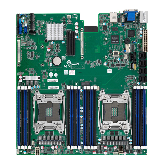
Page 10: Board Image
2.1 Board Image S7076 This picture is representative of the latest board revision available at the time of publishing. The board you receive may not look exactly like the above picture. http://www.tyan.com... -
Page 11: Block Diagram
2.2 Block Diagram S7076 Block Diagram http://www.tyan.com... -
Page 12: Mainboard Mechanical Drawing
2.3 Mainboard Mechanical Drawing http://www.tyan.com... -
Page 13: Board Parts, Jumpers And Connectors
The board you receive may not look exactly like the above diagram. But for the DIMM number please refer to the above placement for memory installation. For the latest board revision, please visit our web site at http://www.tyan.com. http://www.tyan.com... - Page 14 (J20/J21/J22/J23) 41 ATX 24-pin Main Power 19 Front Panel Header (J50) Connector (PW2) 20 PCH SATA SGPIO Header for BB 42 TYAN Module Header (J48) HD Board (J43) 43 FAN Header for BB FAN Board 21 USB3.0 Header (J36) (J29) 22 7-pin Vertical SATA3.0 Connector...
- Page 15 NMI Jumper (J67) CPU0_DIMM_C0/C1 ME Recovery Mode Jumper (J62) CPU0_DIMM_D0/D1 ME Security Override Jumper (J60) CPU0_DIMM_B0/B1 CPU0_DIMM_A0/A1 CPU1_DIMM_G0/G1 CPU1_DIMM_H0/H1 CPU1_DIMM_F0/F1 CPU1_DIMM_E0/E1 Jumper Legend OPEN - Jumper OFF Without jumper cover CLOSED - Jumper ON With jumper cover http://www.tyan.com...
- Page 16 http://www.tyan.com...
- Page 17 J30: CPU1 FAN J31: SYS_FAN_4 J32: SYS_FAN_5 J33: SYS_FAN_1 J34: SYS_FAN_2 J35: SYS_FAN_3 J50: Front Panel Header Signal Signal FP_PW_LED_PW FP_PWR FP_ID_LED_PW PWR_LED- FP_ID_LED_N HDD_LED+ LED_FAULT1 HDD_LED- LED_FAULT2 FP_PWRSW# LAN0_ACT_P LAN0_LED1_ACT# FP_RSTSW# FP_SMBDAT FP_SMBCLK FP_IDLEDSW# FP_INTRUSION# LAN1_ACT_P FP_NMISW# LAN1_LED1_ACT# http://www.tyan.com...
- Page 18 http://www.tyan.com...
- Page 19 Connects to the Serial SATA_TXP_C ATA ready drives via SATA_TXN_C the Serial ATA cable. J45: SATA4 SATA_RXN_C J46: SATA5 SATA_RXP_C J36: USB3.0 Header Signal Signal USB3_VCC_FPB_01 USB3_N5_RX_FPB_N0 USB3_VCC_FPB_01 USB3_P5_RX_FPB_P0 USB3_N6_RX_FPB_N1 USB3_P6_RX_FPB_P1 USB3_N5_TX_FPB_N0 USB3_P5_TX_FPB_P0 USB3_N6_TX_FPB_N1 USB3_P6_TX_FPB_P1 USB2_N12_FPB_N0_R USB2_P12_FPB_P0_R USB2_N11_FPB_N1_R OC_N USB2_P11_FPB_P1_R http://www.tyan.com...
- Page 20 http://www.tyan.com...
- Page 21 J48: TYAN Module Header Signal Signal VCC3 DBG_LFRAME_N DBG_LPC0 DBG_LPC1 TPM_RST# DBG_LPC2 DBG_LPC3 CLK_33M_TPM DBG_SERIRQ DBG_PRES_N VCC3_AUX TPM_ADDR_MB PCH_TPM_PP_EN J40: Vertical Type-A USB Connector Signal Signal USB_VCC_TYPE_A USB_N2_TYPE_A1_R USB_P2_TYPE_A1_R J49: PSMI Connector Signal Signal PSMI_5V_SMBCLK PSMI_5V_SMBDATA PSU_ALERT_N VCC3 J51: IPMB Pin Header...
- Page 22 http://www.tyan.com...
- Page 23 2. Press the button (Clear CMOS). 3. Reconnect power & power on the system. NOTE: After flashing new BIOS, do the following steps: a. Clear CMOS b. Enter BIOS setup menu and load Default Settings. Then do a Save and Exit from setup. http://www.tyan.com...
- Page 24 http://www.tyan.com...
- Page 25 OPEN FM_ME_RCVR_N (Default) Pin1-2 closed: Normal Pin2-3 closed: ME Firmware Recovery Mode J60: Flash Descriptor Security Override Header Signal OPEN MFG_MODE_N Pin1-2 closed: Enable security measures defined in the Flash (Default) Descriptor-Normal Pin2-3 closed: Disable Flash Descriptor Security (override) http://www.tyan.com...
- Page 26 http://www.tyan.com...
- Page 27 J67: NMI Jumper Signal Signal FP_NMI_BTN_N FP_PIN23_N FP_HD_FAULT_LED (Default) Pin1-2 closed: Normal Pin2-3 closed: Remove NMI Button Function http://www.tyan.com...
-
Page 28: Led Definitions
2.5 LED Definitions http://www.tyan.com... - Page 29 The LED lighted up when the system has experienced a fatal or catastrophic error and can not continue to operate. Signal + VCC3_AUX Rear ID LED7 State Description Green Signal CPU0 LED8 State Description PWOK LED Green http://www.tyan.com...
- Page 30 The LED lights up when the Green power of CPU1 is normally. Signal + VCC3_AUX PSU Alert State Description LED10 The LED shuts off when the PSU is normal. The LED lights up when the Green PSU is abnormally. http://www.tyan.com...
-
Page 31: Installing The Processor And Heat Sink
Specifications on page 5. Check our website at for latest processor support. NOTE: MiTAC TYAN is not liable for damage as a result of operating an unsupported configuration. Processor Installation for Socket-R3 (LGA2011) Follow the steps below to install the processors and heat sinks. - Page 32 Remove the CPU protection cap. Install the processor and make sure the gold arrow is located in the right direction. Remove the other CPU protection cap attached on the socket cover. Close the CPU socket cover. http://www.tyan.com...
- Page 33 Close the socket levers. Close the other socket lever. http://www.tyan.com...
- Page 34 Intel . Please refer to the Intel website: http://www.intel.com The following diagram illustrates how to install the heat sink for the S7076. Remove the protective sheet.. Install the CPU heatsink. Secure the heat sink screws.
-
Page 35: Thermal Interface Material
CPU lid (applying too much will actually reduce the cooling). NOTE: Always check with the manufacturer of the heat sink & processor to ensure that the thermal interface material is compatible with the processor and meets the manufacturer’s warranty requirements. http://www.tyan.com... -
Page 36: Tips On Installing Motherboard In Chassis
Some chassis include plastic studs instead of metal. Although the plastic studs are usable, MiTAC recommends using metal studs with screws that will fasten the motherboard more securely in place. Below is a chart detailing what the most common motherboard studs look like and how they should be installed. http://www.tyan.com... - Page 37 http://www.tyan.com...
-
Page 38: Installing The Memory
2.9 Installing the Memory Before installing memory, ensure that the memory you have is compatible with the motherboard and processor. Check the TYAN Web site at http://www.tyan.com details of the type of memory recommended for your motherboard. Supports eight (4+4) 284-Pin DDR4 sockets,... - Page 39 S7076 Recommended Memory Population Table Single CPU Installed (CPU0 only) Quantity of memory installed √ √ √ √ √ √ CPU0_DIMM_A0 √ √ CPU0_DIMM_A1 √ √ √ √ √ CPU0_DIMM_B0 √ √ CPU0_DIMM_B1 √ √ √ CPU0_DIMM_C0 √ CPU0_DIMM_C1 √...
- Page 40 √ √ √ √ √ CPU1_DIMM_E0 √ √ √ CPU1_DIMM_E1 √ √ √ √ √ √ CPU1_DIMM_F0 √ CPU1_DIMM_F1 √ √ √ √ √ √ √ √ CPU1_DIMM_G0 √ √ CPU1_DIMM_G1 √ √ √ √ √ CPU1_DIMM_H0 √ CPU1_DIMM_H1 http://www.tyan.com...
-
Page 41: Memory Installation Procedure
Memory Installation Procedure Follow these instructions to install memory modules into the S7076. Unlock the clips as shown in the illustration. Insert the memory module firmly into the socket by gently pressing down until it sits flush with the socket. -
Page 42: Attaching Drive Cables
2.10 Attaching Drive Cables Attaching Serial ATA Cables six (6) S7076 is equipped with Serial ATA (SATA) channel. Connections for the drives are very simple. There is no need to set Master/Slave jumpers on SATA drives. If you are in need of SATA/SAS cables or power adapters please contact your place of purchase. -
Page 43: Installing Add-In Cards
Doing so allows air to circulate within the chassis more easily, thus improving cooling for all installed devices. NOTE: You must always unplug the power connector to the motherboard before performing system hardware changes to avoid damaging the board or expansion device. http://www.tyan.com... -
Page 44: Connecting External Devices
10/100/1000 Mbps LAN Link/Activity LED Scheme Left LED Right LED Link Green 10 Mbps Active Blinking Green Link Solid Green Green 100 Mbps Active Solid Green Blinking Green Link Solid Yellow Green 1000 Mbps Active Solid Yellow Blinking Green No Link http://www.tyan.com... -
Page 45: Installing The Power Supply
2.13 Installing the Power Supply three (3) There are power connectors on your S7076 motherboard. The S7076 supports EPS 12V power supply. PW2: ATX 24-pin Main Power Connector Signal Signal VCC3 VCC3 VCC3 -12V VCC5 PS_ON# PWR_OK 5VSB VCC5 VCC12... -
Page 46: Finishing Up
In the rare circumstance that you have experienced difficulty, you can find help by asking your vendor for assistance. If they are not available for assistance, please find setup information and documentation online at our website or by calling your vendor’s support line. http://www.tyan.com... -
Page 47: Chapter 3: Bios Setup
The table below shows how to navigate in the setup program using the keyboard. Function Left/Right Arrow Keys Change from one menu to the next Up/Down Arrow Keys Move between selections Enter Open highlighted section PgUp/PgDn Keys Change pages Change options Exit http://www.tyan.com... - Page 48 The following pages provide the details of BIOS menu. Please be noticed that the BIOS menu are continually changing due to the BIOS updating. The BIOS menu provided are the most updated ones when this manual is written. Please visit TYAN’s website at http://www.tyan.com for the information of BIOS updating. http://www.tyan.com...
-
Page 49: Main Menu
It displays BIOS related information. Memory Information This displays the total memory size. System Date Adjust the system date. MM (Months): DD (Days): YYYY (Years) System Time Adjust the system clock. HH (24 hours format): MM (Minutes): SS (Seconds) Access Level Read only. http://www.tyan.com... -
Page 50: Advanced Menu
3.3 Advanced Menu This section facilitates configuring advanced BIOS options for your system. S7076GM2NR (AST2400) http://www.tyan.com... - Page 51 Onboard Device Configuration Onboard Device Configuration. PCIe Slot Configuration Onboard PCIe Slot Configuration. WatchDog Timer Configuration WatchDog Configuration. ASPEED Super IO Configuration System Super IO Chip Parameters. S5 RTC Wake Settings Enable system to wake from S5 using RTC alarm. http://www.tyan.com...
- Page 52 Serial Port Console Redirection Serial Port Console Redirection. PCI Subsystem Settings PCI, PCI-X and PCI Express Settings. CSM Configuration CSM configuration: Enable/Disable, Option ROM execution settings, etc. Trusted Computing Trusted Computing Settings. USB Configuration USB Configuration Parameters. http://www.tyan.com...
- Page 53 3.3.1 ACPI Settings Enable ACPI Auto Configuration Enables or Disables BIOS ACPI Auto Configuration. Disabled / Enabled Enable Hibernation Enable or disable System ability to Hibernate (OS/S4 Sleep State). This option may not be effective with some OS. Disabled / Enabled http://www.tyan.com...
- Page 54 3.3.2 Hardware Health Configuration / H/W Monitor S7076GM2NR (AST2400) http://www.tyan.com...
- Page 55 [Enabled]. PWM Minimal Duty Cycle PWM Minimal Duty Cycle. 30% Duty Cycle / 45% Duty Cycle / 60% Duty Cycle BMC Alert Beep Enable/Disable BMC Alert Beep. On / Off PM Bus Support PM Bus support. Disabled / Enabled http://www.tyan.com...
- Page 56 3.3.2.1 Sensor Data Register Monitoring Read only. http://www.tyan.com...
- Page 57 Disabled / Enabled with PXE / Enabled with iSCSI Chassis Intrusion detect Enabled: When a chassis open event is detected, the BIOS will record the event. Disabled / Enabled NMI Button Enable or Disable NMI button. Disabled / Enabled http://www.tyan.com...
- Page 58 Wait for “ESC” If Error Enable or Disable Wait ESC key Function. When Chassis Intrusion, CMOS Clear or BMC not response. Enabled / Disabled http://www.tyan.com...
- Page 59 PCIe Slot2 OPTIROM Enable/Disable Load OPTROM for PCIe Slot devices. Enabled / Disabled PCIe Slot1 Link Speed / PCIe Slot2 Link Speed OnBoard PCIe Slot Link Speed Configuration. Auto / Gen 1 (2.5GT/s) / Gen 2 (5GT/s) / Gen 3 (8GT/s) http://www.tyan.com...
- Page 60 Disabled / POST / OS / PowerON NOTE: Watch Dog Timer will not appear when Watch Dog Mode is set to [Disabled]. Watch Dog Timer Watch Dog Timer Help. 2 MINS / 4 MINS / 6 MINS / 8 MINS / 10 MINS http://www.tyan.com...
- Page 61 3.3.6 ASPEED Super IO Configuration Super IO Chip Read only. http://www.tyan.com...
- Page 62 / IO=3F8h, IRQ=3, 4, 5, 6, 7, 9, 10, 11, 12; / IO=2F8h; IRQ=3, 4, 5, 6, 7, 9, 10, 11, 12; / IO=3E8h, IRQ=3, 4, 5, 6, 7, 9, 10, 11, 12; / IO=2E8h, IRQ=3, 4, 5, 6, 7, 9, 10, 11, 12; http://www.tyan.com...
- Page 63 / IO=3F8h, IRQ=3, 4, 5, 6, 7, 9, 10, 11, 12; / IO=2F8h; IRQ=3, 4, 5, 6, 7, 9, 10, 11, 12; / IO=3E8h, IRQ=3, 4, 5, 6, 7, 9, 10, 11, 12; / IO=2E8h, IRQ=3, 4, 5, 6, 7, 9, 10, 11, 12; http://www.tyan.com...
- Page 64 Wake system from S5 Enable or disable System wake on alarm event. Select Fixed Time, system will wake on the hr:min:sec specified. Select Dynamic Time, system will wake on the current time + increase minute(s). Disabled / Fixed Time / Dynamic Time http://www.tyan.com...
- Page 65 COM1/COM2/ Serial Port for Out-Of-Band Management/Windows Emergency Services (EMS) Console Redirection Settings The settings specify how the host computer (which the user is using) will exchange data. Both computers should have the same or compatible settings. Legacy Console Redirection Settings Legacy Console redirection settings. http://www.tyan.com...
- Page 66 1’s in the data bits is odd. Mark: parity bit is always 1. Space: parity bit is always 0. Mark and Space parity do not allow for error detection. None / Even / Odd / Mark / Space http://www.tyan.com...
- Page 67 Redirection after BIOS POST The settings specify if BootLoader is selected than Legacy console redirection is disabled before booting to Legacy OS. Default value is Always Enable which means Legacy Console Redirection is enabled for Legacy OS. Always Enable / BootLoader http://www.tyan.com...
- Page 68 3.3.8.2 Legacy Console Redirection Settings Legacy Serial Redirection Port Select a COM port to display redirection of Legacy OS and Legacy OPROM Messages. COM1 / COM2 http://www.tyan.com...
- Page 69 VT-UTF8 / VT100 / VT100+ / ANSI Bits per Second Select serial port transmission speed. The speed must be matched on the other side. Long or noisy lines may require lower speeds. 115200 / 9600 / 19200 / 57600 http://www.tyan.com...
-
Page 70: Flow Control
‘start’ signal can be sent to restart the flow. Hardware flow control uses two wires to send start/stop signal. None / Hardware RTS/CTS / Software Xon/Xoff Data Bits / Parity / Stop Bits Read only. http://www.tyan.com... - Page 71 Enables or Disables 64bit capable Devices to be Decoded in Above 4G Address Space (Only if System Supports 64 bit PCI Decoding). Disabled / Enabled SR-IOV Support If system has SR-IOV capable PCIe Devices, this option enables or disables Single Root IO Virtualization Support. Disabled / Enabled http://www.tyan.com...
- Page 72 3.3.9.1 PCI Express Settings Maximum Payload Set Maximum Payload of PCI Express Device or allow System BIOS to select the value. Auto / 128 Bytes / 256 Bytes / 512 Bytes / 1024 Bytes / 2048 Bytes / 4096 Bytes http://www.tyan.com...
- Page 73 If supported by hardware and set to “Enabled”, the Downstream Port disables its traditional Device Number field being 0 enforcement when turning a Type1 Configuration Request into a Type0 Configuration Request, permitting access to Extended Functions in an ARI Device immediately below the Port. Disabled / Enabled http://www.tyan.com...
- Page 74 Legacy / Do not launch / UEFI Storage Controls the execution of UEFI and Legacy Storage OpROM. Legacy / Do not launch / UEFI Video Controls the execution of UEFI and Legacy Video OpROM Legacy / Do not launch / UEFI http://www.tyan.com...
- Page 75 Other PCI Devices Determines OpROM execution policy for devices other than Network, Storage, or Video. Legacy / Do not launch / UEFI http://www.tyan.com...
- Page 76 3.3.11 Trusted Computing Security Device Support Enables or Disables BIOS support for security device. O.S. will not show Security Device. TCG EFI protocol and INT1a interface will not be available. Disabled / Enabled http://www.tyan.com...
- Page 77 This is a workaround for OSes without XHCI hand-off support. The XHCI ownership change should be claimed by XHCI driver. Disabled / Enabled EHCI Hand-off This is a workaround for OSes without EHCI hand-off support. The EHCI ownership change should be claimed by EHCI driver. Disabled / Enabled http://www.tyan.com...
- Page 78 Maximum time the device will take before it properly reports itself to the Host Controller. AUTO uses default value: for a Root port it is 100 ms, for a Hub port the delay is taken from Hub descriptor. Auto / Manual http://www.tyan.com...
-
Page 79: Intel Rc Setup
Displays and provides option to change the Common RefCode Settings. QPI Configuration Displays and provides option to change teh QPI Settings. Memory Configuration Displays and provides option to change the Memory Settings. IIO configuration Displays and provides option to change the IIO Settings. http://www.tyan.com... - Page 80 PCH configuration Displays and provides option to change the PCH Settings. Miscellaneous Configuration Displays and provides option to change the Miscellaneous Settings. http://www.tyan.com...
- Page 81 Enable / Disable Execute Disable Bit When disabled, forces the XD feature flag to always return 0. Enable / Disable Enables the vanderpool Technology, takes effect after reboot. Enable / Disable Enable SMX Enables Safer Mode Extensions. Disable / Enable http://www.tyan.com...
- Page 82 3.4.1.1 Per-Socket Configuration http://www.tyan.com...
- Page 83 3.4.1.1.1 CPU Socket 0 / Socket 1 Configuration Cores Enabled Number of Cores to Enable. 0 means all cores. 12 Cores available. http://www.tyan.com...
- Page 84 3.4.2 Advanced Power Management Configuration Power Technology Enable the power management features. Energy Efficient / Disabled / Custom NOTE: CPU P State Control and CPU C State Control submenu can be modified in user mode when Power Technology is set to [Custom]. http://www.tyan.com...
- Page 85 When eneabled, OS sets CPU frequency according load. When disabled, CPU frequency is set at max non-turbo. Enabled / Disabled Turbo Mode Turbo mode allows a CPU logical processor to execute a higher frequency when enough power is available not exceed CPU defined limits. Enabled / Disabled http://www.tyan.com...
- Page 86 C0/C1 state / C2 state / C6 (non Retention) state / C6 (Retention) state CPU C3 report Enable/Disable CPU C3 (ACPI C2) report to OS. Recommended to be disabled. Disabled / Enabled CPU C6 report Enable/Disable CPU C6 (ACPI C2) report to OS. Recommended to be enabled. Disabled / Enabled http://www.tyan.com...
- Page 87 MMIOHBase MMIOH Base [63:32] must be between 4032-4078. 56T / 48T / 24T MMIO High Size Select MMIO High Size. 256G / 128G / 512G / 1024G Numa Enable or Disable Non uniform Memory Access (NUMA). Enable / Disable http://www.tyan.com...
- Page 88 3.4.4 QPI Configuration QPI General Configuration Displays and provides option to change the QPI General Settings. http://www.tyan.com...
- Page 89 Allows for selecting the QPI Link Frequency. Auto / 6.4GB/s / 8.0GB/s / 9.6GB/s / Auto Limited Link L0p Enable Link L0p Enable: Disable, Enable (default) Disabled / Enabled Link L1p Enable Link L1p Enable: Disable, Enable (default) Disabled / Enabled http://www.tyan.com...
- Page 90 3.4.4.1.1 QPI Status QPI Status Read only. http://www.tyan.com...
- Page 91 ECC Support Enable/disable DDR ECC Support. Auto / Disable / Enable Memory Type Selects the Memory type supported by this platform. RDIMMs only / UDIMMs only / UDIMMs and RDIMMs Data Scrambling Enables data scrambling. Auto / Disabled / Enabled http://www.tyan.com...
- Page 92 3.4.5.1 Memory Topology This submenu can’t be modified in user mode. Read only. http://www.tyan.com...
- Page 93 3.4.5.2 Memory Thermal Set Throttling Mode Configure Thermal Throttling Mode. Select OLTT or CLTT mode. Disabled / OLTT / CLTT http://www.tyan.com...
- Page 94 3.4.5.3 Memory Map Channel Interleaving Select Channel Interleaving setting. Auto / 1-way Interleave / 2-way Interleave / 3-way Interleave / 4-way Interleave Rank Interleaving Select Rank Interleaving setting. Auto / 1-way Interleave / 2-way Interleave / 4-way Interleave / 8-way Interleave http://www.tyan.com...
- Page 95 Sparing will be selected. Disable / Mirror / Lockstep Mode Lockstep x4 DIMMs Enable/Disasle Lockstep for x4 DIMMs. Auto / Disabled / Enabled Memory Rank Sparing Enable/Disable Memory Rank Sparing. Disabled / Enabled Device Tagging Enable/Disable Device Tagging Disable / Enable http://www.tyan.com...
- Page 96 3.4.6 IIO Configuration IOAT Configuration All IOAT configuration options. Intel VT for Directed I/O (VT-d) Press <Enter> to bring up the Intel VT for Directed I/O (VT-d) Configuration menu. http://www.tyan.com...
- Page 97 3.4.6.1 IOAT Configuration Enable IOAT Control to enable/disable IOAT devices. Disable / Enable http://www.tyan.com...
- Page 98 3.4.6.2 Intel VT for Directed I/O (VT-d) Intel VT for Directed I/O (VT-d) Enable/Disable Intel Virtualization Technology for Directed I/O (VT-d) by reporting the I/O device assignment to VMM through DMAR ACPI Tables. Enable / Disable http://www.tyan.com...
- Page 99 3.4.7 PCH Configuration PCH Devices Enable/Disable Intel® IO Controller Hub devices PCH sSATA Configuration sSATA devices and settings. PCH SATA Configuration SATA devices and settings. USB Configuration USB Configuration Settings. http://www.tyan.com...
- Page 100 3.4.7.1 PCH Devices S7076GM2NR (AST2400) http://www.tyan.com...
- Page 101 DeepSx Power Policies Configure the DeepSx Mode configuration. Disabled / Enabled in S5 / Enabled in S4-S5 / Enabled in S3-S4-S5 PCH state after G3 Select S0/S5 for ACPI state after a G3. S5 / S0 / Last State http://www.tyan.com...
- Page 102 Idedntify the SATA port is connected to Solid State Drive or Hard Disk Drive. IDE / AHCI / RAID Support Aggressive Link Power Management Enable/Disable SALP. Enabled / Disabled sSATA Port 0/1/2/3 Read only. Port 0/1/2/3 Enable or Disable SATA Port Enabled / Disabled http://www.tyan.com...
- Page 103 Otherwise all drives spin up at boot. Disabled / Enabled sSATA Device Type Identify the SATA port is connected to Solid State Drive or Hard Disk Drive. Hard Disk Drive / Solid State Drive http://www.tyan.com...
- Page 104 Configure SATA as Idedntify the SATA port is connected to Solid State Drive or Hard Disk Drive. IDE / AHCI / RAID Support Aggressive Link Power Management Enable/Disable SALP. Enabled / Disabled SATA Port 0/1/2/3 Read only. Software Preserve Read only. http://www.tyan.com...
- Page 105 Otherwise all drives spin up at boot. Disabled / Enabled SATA Device Type Identify the SATA port is connected to Solid State Drive or Hard Disk Drive. Hard Disk Drive / Solid State Drive http://www.tyan.com...
- Page 106 3.4.7.4 USB Configuration XHCI Mode Mode of operationof XHCI controller. Smart Auto / Auto / Enabled / Disabled / Manual http://www.tyan.com...
- Page 107 3.4.8 Miscellaneous Configuration Active Video Select active Video type. Offboard Device / Onboard Device http://www.tyan.com...
-
Page 108: Server Management (Reserved For Bb)
3.5 Server Management (reserved for BB) System Event Log Press <Enter> to change the SEL event log configuration. BMC network configuration Configure BMC network parameters. http://www.tyan.com... - Page 109 Choose options for reactions to a full SEL. Do Nothing / Erase Immediately Log EFI Status Codes Disable the logging of EFI Status Codes or log only error code or only progress code or both. Both / Disabled / Error Code / Progress Code http://www.tyan.com...
- Page 110 BMC). “Current setting” option will not modify any BMC network parameters during BIOS phase. Current setting / Static / DHCP IP Address Source / Station IP address / Subnet mask / Station MAC address / Router IP address / Router MAC address Read only. http://www.tyan.com...
-
Page 111: Security
Confirm New Password window will pop out to ask for confirmation. User Password Set user password in the Create New Password window. After you key in the password, the Confirm New Password window will pop out to ask for confirmation. http://www.tyan.com... - Page 112 3.6.1 Secure Flash Update Read only. http://www.tyan.com...
-
Page 113: Boot
On / Off Quiet Boot Enable or disable Quiet Boot option. Disabled / Enabled Endless Boot Enable or disable Endless Boot option. Disabled / Enabled Boot Option #1 Set the system boot order. UEFI: SanDisk (Device name) / Disabled http://www.tyan.com... - Page 114 3.7.1 Delete Boot Option Delete Boot Option Remove an EFI boot option from the boot order. Select one to Delete / UEFI: Built-in EFI Shell / UEFI: SanDisk http://www.tyan.com...
-
Page 115: Save & Exit
Discard Changes and Reset Reset system setup without saving any changes. Save Options Read only. Save Changes Save changes done so far to any of the setup options. Discard Changes Discard changes done so far to any of the setup options. http://www.tyan.com... - Page 116 Restore Defaults Restore/Load Default values for all the setup options. Save as User Defaults Save the changes done so far as User Defaults. Restore User Defaults Restore the User Defaults to all the setup options. http://www.tyan.com...
-
Page 117: Chapter 4: Diagnostics
BIOS flash failure, you must contact your dealer for a replacement BIOS. There are no exceptions. TYAN does not have a policy for replacing BIOS chips directly with end users. In no event will TYAN be held responsible for damages done by the end user. -
Page 118: Amibios Post Code (Aptio)
South Bridge initialization before microcode loading 0x05 OEM initialization before microcode loading 0x06 Microcode loading 0x07 AP initialization after microcode loading 0x08 North Bridge initialization after microcode loading 0x09 South Bridge initialization after microcode loading 0x0A OEM initialization after microcode loading 0x0B Cache initialization http://www.tyan.com... - Page 119 CPU post-memory initialization is started 0x33 CPU post-memory initialization. Cache initialization 0x34 CPU post-memory initialization. Application Processor(s) (AP) initialization 0x35 CPU post-memory initialization. Boot Strap Processor (BSP) selection 0x36 CPU post-memory initialization. System Management Mode(SMM) initialization 0x37 Post-Memory North Bridge initialization is started http://www.tyan.com...
- Page 120 Reserved for future AMI progress codes S3 Resume Error Codes 0xE8 S3 Resume Failed 0xE9 S3 Resume PPI not Found 0xEA S3 Resume Boot Script Error 0xEB S3 OS Wake Error 0xEC – 0xEF Reserved for future AMI error codes http://www.tyan.com...
- Page 121 CPU DXE initialization (CPU module specific) 0x67 CPU DXE initialization (CPU module specific) 0x68 PCI host bridge initialization 0x69 North Bridge DXE initialization is started 0x6A North Bridge DXE SMM initialization is started 0x6B North Bridge DXE initialization (North Bridge module specific) http://www.tyan.com...
- Page 122 USB initialization is started 0x9B USB Reset 0x9C USB Detect 0x9D USB Enable 0x9E -0x9F Reserved for future AMI codes 0xA0 IDE initialization is started 0xA1 IDE Reset 0xA2 IDE Detect 0xA3 IDE Enable 0xA4 SCSI initialization is started http://www.tyan.com...
- Page 123 No Console Output Devices are found 0xD7 No Console Input Devices are found 0xD8 Invalid password 0xD9 Error loading Boot Option (LoadImage returned error) 0xDA Boot Option is failed (StartImage returned error) 0xDB Flash update is failed 0xDC Reset protocol is not available http://www.tyan.com...
- Page 124 System is waking up from the S3 sleep state 0x40 System is waking up from the S4 sleep state 0xAC System has transitioned into ACPI mode. Interrupt controller is in PIC mode. 0xAA System has transitioned into ACPI mode. Interrupt controller is in APIC mode. http://www.tyan.com...
-
Page 125: Appendix: Fan And Temp Sensors
This section aims to help readers identify the locations of some specific FAN and Temp Sensors on the motherboard. A table of BIOS Temp sensor name explanation is also included for readers’ reference. NOTE: The red mark indicates the sensor. http://www.tyan.com... - Page 126 (rpm) Temp Sensor: Temp. Temp sensor detects the system temperature around. NOTE: The system temperature is measured in a scale defined by Intel, not in Fahrenheit or Celsius. BIOS Temp Sensor Name Explanation: http://www.tyan.com...
- Page 127 http://www.tyan.com...
- Page 128 Fan Speed of SYS_FAN_5 SYS_FAN_6 Fan Speed of SYS_FAN_6 SYS_FAN_7 Fan Speed of SYS_FAN_7 SYS_FAN_8 Fan Speed of SYS_FAN_8 SYS_FAN_9 Fan Speed of SYS_FAN_9 SYS_FAN_10 Fan Speed of SYS_FAN_10 SYS_FAN_11 Fan Speed of SYS_FAN_11 SYS_FAN_12 Fan Speed of SYS_FAN_12 http://www.tyan.com...
-
Page 129: Glossary
(reading to or writing from a disk drive a single time is much faster than doing so repeatedly) there is the possibility of losing your data should the system crash. Information in a buffer is temporarily stored, not permanently saved. http://www.tyan.com... - Page 130 (like soundcards or keyboards) to access the main memory without involving the CPU. This frees up CPU resources for other tasks. As with IRQs, it is vital that you do not double up devices on a single line. Plug-n-Play devices will take care of this for you. http://www.tyan.com...
- Page 131 EEPROM (Electrically Erasable Programmable ROM): also called Flash BIOS, it is a ROM chip which can, unlike normal ROM, be updated. This allows you to keep ® up with changes in the BIOS programs without having to buy a new chip. TYAN ’s BIOS updates can be found at http://www.tyan.com...
- Page 132 PXE (Preboot Execution Environment): one of four components that together make up the Wired for Management 2.0 baseline specification. PXE was designed to define a standard set of preboot protocol services within a client with the goal of allowing networked-based booting to boot using industry standard protocols. http://www.tyan.com...
- Page 133 NVIDIA s (graphics communications processing units) and NVIDIA MCPs (media and processors). application Depending on the , NVIDIA SLI can deliver as much as two times the performance of a single GPU configuration. http://www.tyan.com...
- Page 134 CPUs without damaging the sensitive CPU pins. The CPU is lightly placed in an open ZIF socket, and a lever is pulled down. This shifts the processor over and down, guiding it into the board and locking it into place. http://www.tyan.com...
-
Page 135: Technical Support
(which can have expensive consequences). If these options are not available for you then TYAN can help. Besides designing innovative and quality products for over a decade, TYAN has continuously offered customers service beyond their expectations. - Page 136 (RMA) number. The RMA number Should be prominently displayed on the outside of the shipping carton and the package should be mailed prepaid. TYAN will pay to have the board shipped back to you. Notice for the USA Compliance Information Statement (Declaration of...
Need help?
Do you have a question about the S7076 and is the answer not in the manual?
Questions and answers