Table of Contents
Advertisement
Quick Links
Copyright
Copyright © 2017 MiTAC International Corporation. All rights reserved. No part of
this manual may be reproduced or translated without prior written consent from
MiTAC International Corporation.
Trademark
All registered and unregistered trademarks and company names contained in this
manual are property of their respective owners including, but not limited to the
following.
®
TYAN
is a trademark of MiTAC International Corporation.
®
Intel
is a trademark of Intel
AMI, AMI BIOS are trademarks of AMI Technologies.
®
Microsoft
, Windows
®
Winbond
is a trademark of Winbond Electronics Corporation.
Notice
Information contained in this document is furnished by MiTAC International
Corporation and has been reviewed for accuracy and reliability prior to printing.
MiTAC assumes no liability whatsoever, and disclaims any express or implied
warranty, relating to sale and/or use of TYAN
warranties relating to fitness for a particular purpose or merchantability. MiTAC
retains the right to make changes to product descriptions and/or specifications at
any time, without notice. In no event will MiTAC be held liable for any direct or
indirect, incidental or consequential damage, loss of use, loss of data or other
malady resulting from errors or inaccuracies of information contained in this
document.
S7100
Version 1.0
®
Corporation.
®
are trademarks of Microsoft Corporation.
http://www.tyan.com
®
products including liability or
1
Advertisement
Table of Contents

Subscribe to Our Youtube Channel
Related Manuals for TYAN S7100


Summary of Contents for TYAN S7100
-
Page 1: S7100
Corporation and has been reviewed for accuracy and reliability prior to printing. MiTAC assumes no liability whatsoever, and disclaims any express or implied ® warranty, relating to sale and/or use of TYAN products including liability or warranties relating to fitness for a particular purpose or merchantability. MiTAC retains the right to make changes to product descriptions and/or specifications at any time, without notice. -
Page 2: Table Of Contents
Contents S7100 ......................1 Before you begin… ..................3 Chapter 1: Instruction ................4 1.1 Congratulations ................. 4 1.2 Hardware Specifications ..............4 1.3 Software Specifications ..............8 Chapter 2: Board Installation ..............9 2.1 Board Image ..................10 2.2 Block Diagram ................. 11 2.3 Motherboard Mechanical Drawing ........... -
Page 3: Before You Begin
Before you begin… Check the box contents! The retail motherboard package should contain the following: 1 x S7100 Motherboard 1 x Rear IO shielding 1 x S7100 Quick Installation Guide ® 1 x TYAN Driver CD 2 x SATA Single Cable... -
Page 4: Chapter 1: Instruction
2666MHz / DDR4 memory. Leveraging advanced technology ® from Intel , the S7100 is capable of offering scalable 32 and 64-bit computing, high- bandwidth memory design, and lightning-fast PCI-E bus implementation. The S7100 not only empowers you in today‟s demanding IT environment but also offers a smooth path for future application upgradeability. - Page 5 Please refer to our TPM supported TPM (Optional) TPM Support list. Chipset Aspeed AST2500 Total (6) 4-pin headers Monitors temperature for CPU & Temperature System Monitoring memory & system environment Monitors voltage for CPU, memory, Voltage chipset & power supply Over temperature warning indicator, http://www.tyan.com...
- Page 6 Humidity RoHS RoHS 6/6 Compliant Please refer to our Intel OS Operating System OS supported list supported list. Motherboard (1) S7100 Motherboard (1) Web User's manual, (1) Quick Package Contains Manual Installation Guide Installation CD (1) TYAN installation CD S7100AG2NR...
- Page 7 (3) USB 2.0 ports (2 via cable, 1 TYPE-A), (6) USB 3.0 ports (4 at rear, 2 via cable) (1) header Input /Output RJ-45 (2) GbE ports Front Panel (1) 2 x 5 header (2) SATA-III connectors + (3) Mini-SAS SATA HD (4-in-1) connectors http://www.tyan.com...
-
Page 8: Software Specifications
(1) Web User's manual, (1) Quick Package Contains Manual Installation Guide Installation CD (1) TYAN installation CD 1.3 Software Specifications For the latest AST2500 User‟s Guide and OS (operation system) support, please visit the Tyan‟s Web site at http://www.tyan.com for the latest information http://www.tyan.com... -
Page 9: Chapter 2: Board Installation
Caution! To avoid damaging the motherboard and associated components, do not use torque force greater than 7kgf/cm (6.09 lb/in) on each mounting screw for motherboard installation. Do not apply power to the board if it has been damaged. http://www.tyan.com... -
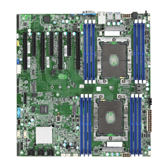
Page 10: Board Image
2.1 Board Image S7100 This picture is representative of the latest board revision available at the time of publishing. The board you receive may not look exactly like the above picture. http://www.tyan.com... -
Page 11: Block Diagram
2.2 Block Diagram S7100 Block Diagram Audio Kit http://www.tyan.com... -
Page 12: Motherboard Mechanical Drawing
2.3 Motherboard Mechanical Drawing http://www.tyan.com... -
Page 13: Board Parts, Jumpers And Connectors
The board you receive may not look exactly like the above diagram. The DIMM slot numbers shown above can be used as a reference when reviewing the DIMM population guidelines shown later in the manual. For the latest board revision, please visit our web site at http://www.tyan.com. http://www.tyan.com... -
Page 14: Motherboard Components
14. COM2 Port Header (HD_COM2) 33. CPU FAN Connector (CPU0_FAN) 15. M.2 Socket, type 2242/2260/2280(NGFF1) 34. 8-pin Power Connector (PWCN3) 16. TYAN Module Header (DBG_HD1) 35.System Fan Connector(SYS_FAN_1) 17. VGA2 Header (VGA2) 36. 24-pin Power Connector (PWCN1) 18. System Fan Header (Fan_HD1) 37. - Page 15 Note: A 4-pin fan without FAN speed Control FPIO: Front Panel Header Signal Signal PW_LED+ FP_PWR ID_LED+ PWR_LED ID_LED- HDD_LED+ FAULT_LED1- HDD_LED- FAULT_LED2- PWR_SW# LAN1 ACTLED+ GND1 LAN1_ACTLED- RST_SW# SMBDATA GND2 SMBCLK SYS_ID_SW# INTRUSION# TEMP SENSOR LAN2_ACTLED+ NMI_SW# LAN2_ACTLED- http://www.tyan.com...
- Page 16 LINE1_JD FRONT_L AGND FRONT_R FRONT_JD SURR_R AGND SURR_L SURR_JD CENTEROUT_L AGND CENTEROUT_R CENTEROUT_JD SIDESURR_R AGND SIDESURR_L SIDESURR_JD DBG_HD1: TYAN Module Header Signal Signal P3V3 FRAME_N LAD0 LAD1 PLT_RST_N LAD2 LAD3 CLK_24M DBG_SERIRQ DBG_PRES_N VCC3_AUX TPM_ADDR_MB PCH_TPM_PP_EN USB3_FPIO2: Front USB3.0 Header...
- Page 17 USB2_N USB2_N USB2_P USB2_P GND1 GND2 FAN_HD1: System Fan Header Signal Signal TACH1 TACH6 TACH2 TACH7 TACH3 TACH8 TACH4 TACH9 TACH5 TACH10 PWM2 PWM1 TACH11 SMB_DATA TACH12 SMB_CLK VCC3_AUX PWM3 IPMB_HD1: IPMB Pin Header Signal Signal IPMB_DAT GND1 IPMB_CLK http://www.tyan.com...
- Page 18 Name TYPE SATA TX DP SATA TX DN SATA RX DN SATA RX DP Connects to the Serial ATA ready drives via the Serial ATA cable. J202: INTRUDER Jumper Signal PCH_Intruder Normal Mode (Default) ME in Force Update Mode http://www.tyan.com...
- Page 19 3. Move the jumper cap to close Pin_1 and Pin_2 for several seconds to Clear CMOS. Clear CMOS 4. Put jumper cap back to Pin_2 and Pin_3 (Default setting). 5. Reconnect power connectors to the motherboard and power on system. http://www.tyan.com...
-
Page 20: Installing The Processor And Heatsink
2.5 Installing the Processor and Heatsink The types of processors supported by the S7100 are listed in the 1.2 Hardware Specifications section on page 4. Check our website at http://www.tyan.com ® the latest list of validated Intel processors for this specific motherboard. - Page 21 Then place the heatsink onto the top of the CPU socket. Align the heatsink by the guide pins and make sure the gold arrow is located in the correct direction. Then place the heatsink onto the top of the processor. http://www.tyan.com...
- Page 22 To secure the heatsink, use a Security T30 Security Torx to tighten the screws in a sequential order (1->2->3->4). When dissembling the heatsink, loosen the screws in reverse order (4->3->2->1). http://www.tyan.com...
-
Page 23: Tips On Installing Motherboard In Chassis
Be especially careful to look for extra stand-offs. If there are any stand-offs present that are not aligned with a mounting hole on the motherboard, it will likely short components on the back of the motherboard when installed. This will cause malfunction and/or damage to your motherboard. http://www.tyan.com... - Page 24 Some chassis include plastic studs instead of metal. Although the plastic studs are usable, MiTAC recommends using metal studs with screws that will fasten the motherboard more securely in place. Below is a chart detailing what the most common motherboard studs look like and how they should be installed. http://www.tyan.com...
-
Page 25: Installing The Memory
2.7 Installing the Memory Before installing memory, ensure that the memory you have is compatible with the motherboard and processor. Check the TYAN Web site at http://www.tyan.com details of the type of memory recommended for your motherboard. Supports up to... - Page 26 √ √ √ √ P0_MCO_DIM_CH_F0 √ √ √ √ √ √ √ P1_MCO_DIM_CH_A0 √ √ √ √ √ √ P1_MCO_DIM_CH_B0 √ √ √ √ √ P1_MCO_DIM_CH_C0 √ √ √ √ P1_MCO_DIM_CH_D0 √ √ √ P1_MCO_DIM_CH_E0 √ √ P1_MCO_DIM_CH_F0 √ http://www.tyan.com...
-
Page 27: Memory Installation Procedure
Memory Installation Procedure Follow these instructions to install memory modules into the S7100. Unlock a DIMM socket by Press the retaining clip outwardly in the following illustration. Align the memory module with the socket,such that the DIMM NOTCH match the KEY SLOT on the socket. -
Page 28: Attaching Drive Cables
The following illustrates how to make a SATA Cable connection. If you are in need of SATA/SAS cables or power adapters please contact your local sales representative. 1. SATA drive cable connection 2. SATA drive power connection 3. SATA cable motherboard connector 4. SATA drive power adapter http://www.tyan.com... -
Page 29: Installing Add-In Cards
Doing so allows air to circulate within the chassis more easily, thus improving cooling for all installed devices. NOTE: You must always unplug the power connector from the motherboard before performing system hardware changes to avoid damaging the board or expansion device. http://www.tyan.com... -
Page 30: Connecting External Devices
The chart below illustrates the different LED states. 10/100/1000 Mbps LAN Link/Activity LED Scheme Left LED Right LED Link Green 10 Mbps Active Blinking Green Link Green Green 100 Mbps Active Blinking Green Green Link Green Amber 1000 Mbps Active Blinking Green Amber No Link http://www.tyan.com... -
Page 31: Installing The Power Supply
2.11 Installing the Power Supply There are Three (3) power connectors on your S7100 motherboard. The S7100 supports EPS 12V power supply. PWCN1: 24-Pin Power Connector Signal Signal +3.3V_1 +3.3V_4 +3.3V_2 -12V COM_1 COM_4 +5V_1 PS-ON# COM_2 COM_5 +5V_2 COM_6... -
Page 32: Chapter 3: Bios Setup
Select the previous or next value/setting of the field <ESC> Exit current menu <F1> General help <F2> Previous values <F3> Load the Optimal default configuration values of the menu <F4> Save and exit <PgUp> / <PgDn> Move cursor to next/previous page http://www.tyan.com... - Page 33 BIOS menus are continually changing due to continual BIOS updates over the product lifespan of the motherboard. The BIOS menus provided are current as of the date when this manual was written. Please visit TYAN‟s website at http://www.tyan.com for information on BIOS updates available for this specific motherboard.
-
Page 34: Main Menu
BIOS Information It displays BIOS related information. Platform Information It displays Platform information. Memory Information This displays the total memory size. System Language Choose the system default language. System Date Adjust the system date. MM (Months): DD (Days): YYYY (Years) http://www.tyan.com... - Page 35 System Time Adjust the system clock. HH (24 hours format): MM (Minutes): SS (Seconds) http://www.tyan.com...
-
Page 36: Advanced Menu
Trusted Computing Trusted Computing settings. ACPI Settings System ACPI Parameters. S5 RTC Wake Settings Enable system to wake from S5 using RTC alarm Serial Port Console Redirection Serial Port Console Redirection PCI Subsystem Settings PCI, PCI-X and PCI Express Settings http://www.tyan.com... - Page 37 CSM Configuration: Enable/Disable Option ROM execution settings, etc USB Configuration USB Configuration Parameters. Onboard Device Configuration Onboard Device and Function Configuration. Option ROM Dispatch Policy Option ROM Dispatch Policy AST2500 Super IO Configuration System Super IO Chip Parameters Hardware Health Configuration Hardware Health Configuration http://www.tyan.com...
- Page 38 3.3.1 iSCSI Configuration iSCSI Name The worldwide unique name of iSCSI Initiator. Only IQN format is accepted. Range is from 4 to 223. http://www.tyan.com...
- Page 39 3.3.2 Intel(R) Virtual RAID on CPU http://www.tyan.com...
- Page 40 3.3.3 Trusted Computing Security Device Support Enable or disable BIOS support for security device. O.S. will not show Security device. TCG EFI protocol and INT1A interface will not be available. Enabled / Disabled http://www.tyan.com...
- Page 41 Enable ACPI Auto Configuration Enables or Disables BIOS ACPI Auto Configuration Disabled / Enabled Enable Hibernation Enables or Disables System ability to Hibernate (OS/S4 Sleep State). This option may not be effective with some operation systems. Disabled / Enabled http://www.tyan.com...
- Page 42 When set to [Fixed Time] wake up hour Select 0-23 for example enter 8 for 3am and 15 for 3pm wake up minute Select 0-59 wake up second Select 0-59 When set to [Dynamic Time] , Wake up minute increase http://www.tyan.com...
- Page 43 The settings specify how the host computer and the remote computer (which the user is using) will exchange data. Both computers should have the same or compatible settings. NOTE: Console Redirection Settings menu only appear when Console Redirection was set to [Enabled]. http://www.tyan.com...
- Page 44 1‟s in the data bits is odd. Mark: parity bit is always 1. Space: parity bit is always 0. Mark and Space parity do not allow for error detection. None / Even / Odd / Mark / Space http://www.tyan.com...
- Page 45 VT100 / LINUX / XTERMR6 / SCO / ESCN / VT400 Redirection After BIOS POST The settings specify if BootLoader is selected than Legacy console redirection is disabled before booting to Legacy OS. Default value is always enable means Legacy. Always Enable / Bootloader http://www.tyan.com...
- Page 46 3.3.6.2 Legacy Console Redirection Settings Legacy Serial Redirected Port Select a COM port to display redirection of Legacy OS and Legacy OPROM Messages COM1 http://www.tyan.com...
- Page 47 VT-UTF8 / VT100 / VT100+ / ANSI Bits per Second Select serial port transmission speed. The speed must be matched on the other side. Long or noisy lines may require lower speeds. 115200 / 9600 / 19200 / 57600 http://www.tyan.com...
- Page 48 „start‟ signal can be sent to restart the flow. Hardware flow control uses two wires to send start/stop signal. None / Hardware RTS/CTS / Software Xon/Xoff Data Bits / Parity / Stop Bits Read only. http://www.tyan.com...
- Page 49 Enables or Disables 64 bit capable Devices to be Decoded in Above 4G Address Space(Only if System Supports 64 bit PCI Decoding). Disabled / Enabled SR-IOV Support If system has SR-IOV capable PCIe Devices,this option Enables or Disables Single Root IO virtualization Support. Disabled / Enabled http://www.tyan.com...
- Page 50 3.3.8 Network Stack Configuration Network Stack Enable / Disable UEFI Network Stack. Disabled / Enabled http://www.tyan.com...
- Page 51 Do not launch / UEFI / legacy Video Controls the execution of UEFI and Legacy Video OpROM Do not launch / UEFI / legacy Other PCI devices Determines OpRom execution policy for devices other than Network, Storage, or Video UEFI / legacy http://www.tyan.com...
- Page 52 USB Mass Storage Driver Support Enable/Disable USB Mass Storage Driver Support. Disabled / Enabled Port 60/64 Emulation Enable I/O port 60h/64h emulation support. This should be enabled for the complete USB keyboard legacy support for non-USB aware OSes. Disabled / Enabled http://www.tyan.com...
- Page 53 Controller. AUTO uses default value: for a Root port it is 100 ms, for a Hub port the delay is taken from Hub descriptor. Auto / Manual 3.3.11 Onboard Device Configuration Enable or disable onboard VGA Disabled / Enabled LAN1 LAN Enable/Disable control function. Disabled / Enabled http://www.tyan.com...
- Page 54 Enable or Disable NMI button Disabled / Enabled 3.3.12 Option ROM Dispatch Policy Configuration Onboard LAN1 (I350) Enable or Disable onboard LAN1 Option ROM. Disabled / Enabled Onboard LAN2 (I350) Enable or Disable onboard LAN2 Option ROM. Disabled / Enabled http://www.tyan.com...
- Page 55 PCIE_1/2/3/4/5/6/7 Empty Enable or Disable Option ROM execution for selected Slot Disabled / Enabled 3.3.13 AST2500 Super IO Configuration Super IO Chip Read only. http://www.tyan.com...
- Page 56 / IO=3F8h, IRQ=3, 4, 5, 6, 7, 9, 10, 11, 12; / IO=2F8h; IRQ=3, 4, 5, 6, 7, 9, 10, 11, 12; / IO=3E8h, IRQ=3, 4, 5, 6, 7, 9, 10, 11, 12; / IO=2E8h, IRQ=3, 4, 5, 6, 7, 9, 10, 11, 12; http://www.tyan.com...
- Page 57 Item will appear. PWM Minimal Duty Cycle PWM Minimal Duty Cycle 30% Duty Cycle / 45% Duty Cycle / 60% Duty Cycle BMC Alert Beep Enable/Disable BMC Alert Beep On / Off PMBus Support PMBus Support Disabled / Enabled http://www.tyan.com...
- Page 58 3.3.14.1 Sensor Data Register Monitoring When you enter the Sensor Data Register Monitoring submenu, you will see the following dialog window pop out. Please wait 8~10 seconds. NOTE 1: SDR can not be modified. Read only. http://www.tyan.com...
- Page 59 http://www.tyan.com...
-
Page 60: Platform Configuration Menu
3.4 Platform Configuration Menu PCH Configuration Displays and provides option to change the PCH Settings. Miscellaneous Configuration Miscellaneous Configuration Server ME Configuration Configure Server ME technology Parameters http://www.tyan.com... - Page 61 Enable/Disable Intel(R) IO Controller Hub devices PCI Express Configuration PCI Express Configuration settings PCH SATA Configuration SATA devices and settings PCH sSATA Configuration sSATA devices and settings USB Configuration USB Configuration Settings PCH DFX Configuration PCH DFX Configuration Options http://www.tyan.com...
- Page 62 3.4.1.1 PCH Devices Configuration PCH state after G3 Select S0/S5 for ACPI state after a G3 S0 /S5 / Leave power state unchanged http://www.tyan.com...
- Page 63 3.4.1.2 PCI Express Configuration PCI Express Root Port 1/2/3/4/5/6/7/8/9/10/11/12/13/14/15/16/17/18/19/20 PCI Express Root Port Settings http://www.tyan.com...
- Page 64 Disabled / L1.1 / L1.2 / L1.1 & L1.2 PCIe Speed PCI Express Root Port Completion Timer TO settings Auto / Gen1 / Gen2 / Gen3 Max Payload Size PCIE Max Payload Size Selection. MPL 128B / MPL 256B http://www.tyan.com...
- Page 65 3.4.1.3 PCH SATA Configuration Submenu http://www.tyan.com...
- Page 66 Indentify the SATA port is connected to Solid State Drive or Hard Disk Drive AHCI / RAID SATA Port 0/1/2/3/4/5/6/7 Port 0/1/2/3/4/5/6/7 Disabled / Enabled Hot Plug Enable/Disable SATA Ports Hot Plug Support. Disabled / Enabled Configure as eSATA Configures port as External SATA (eSATA) Disabled / Enabled http://www.tyan.com...
- Page 67 Spin Up Device AHCI Supports Staggered Spin-up Disabled / Enabled SATA Device Type Indentify the SATA port is connected to Solid State Drive or Hard Disk Drive Hard Disk Drive / Solid State Drive http://www.tyan.com...
- Page 68 3.4.1.4 PCH sSATA Configuration Submenu http://www.tyan.com...
- Page 69 Otherwise all drives spin up at boot. Disable / Enable sSATA Device Type Indentify the SATA port is connected to Solid State Drive or Hard Disk Drive Hard Disk Drive / Solid State Drive http://www.tyan.com...
- Page 70 USB Configuration Submenu XHCI Idle L1 Enable XHCI Idle L1. Disabled to workaround USB3 hot plug will fail after 1 hot plug removal. Please put the system to G3 for the new settings to take effect. Disable / Enable http://www.tyan.com...
- Page 71 Platform-POR / Enabled / Disabled Enable/Disable ADR Timer Held-off for DEBUG PURPOSES ONLY! Platform-POR / Enabled / Held-off ADR timer expire time Select proper ADR timer value: 25uS,50uS,100uS or 0. Platform-POR / 25 uS / 50 uS / 100 uS / 0 uS http://www.tyan.com...
- Page 72 Select proper ADR timer multiplier: x1,8,24,40,56,64,72,80,88,96. Platform-POR / x1 / x8 / x24 / x40 / x56 / x64 / x72 / x80 / x88 /x96 3.4.2 Miscellaneous Configuration Submenu Active Video Select active Video type Auto / Onboard Device / PCIE Device http://www.tyan.com...
- Page 73 3.4.3 Server ME Configuration Submenu Only Read http://www.tyan.com...
-
Page 74: Socket Configuration
Displays and provides option to change the UPI Settings Memory Configuration Displays and provides option to change the Memory Settings IIO Configuration Displays and provides option to change the IIO Settings Advance Power Management Configuration Displays and provides option to change the Power Management Settings http://www.tyan.com... - Page 75 This should be enabled in order to boot legacy OSes that cannot support CPUs with extended CPUID functions. Disabled / Enabled Execute Disable Bit When disabled, forces the XD feature flag to always return 0. Disabled / Enabled Enable Intel(R) TXT Enables Intel(R) TXT Disabled / Enabled http://www.tyan.com...
- Page 76 MLC Streamer Prefetcher (MSR 1A4h Bit [0]) Disabled / Enabled Adjacent Cache Prefetch MLC Spatial Prefetcher (MSR 1A4h Bit [1]) Disabled / Enabled Extended APIC Enable/disable extended APIC support Disabled / Enabled AES-NI Enable/disable AES-NI support Disabled / Enabled 3.5.2 Common RefCode Configuration Submenu http://www.tyan.com...
- Page 77 Per stack mmioh resource assignments are multiples of the granularity where 1 unit Per stack is the default allocation. 1G / 4G / 16G / 64G / 256G / 1024G Numa Enable or Disable non uniform Memory Access. (NUMA) Enabled / Disabled http://www.tyan.com...
- Page 78 3.5.3 UPI Configuration Submenu http://www.tyan.com...
- Page 79 Enable – Set the c_L0p_en, Disable – Reset it, Auto – Auto decides based on Si Compatibility Disable/Enable/Auto Link L1 Enable Enable – Set the c_L1_en, Disable – Reset it, Auto – Auto decides based on Si Compatibility Disable/Enable/Auto http://www.tyan.com...
- Page 80 3.5.3.2 UPI Status Configuration Submenu http://www.tyan.com...
- Page 81 Enable – Enables DDR ECC Support. Disable – Disables this feature. Auto – Sets it to MRC default setting; current default is Enable. Disabled / Enabled Memory Topology Displays memory topology with Dimm population information Memory RAS Configuration Displays and provides option to change the Memory Ras Settings http://www.tyan.com...
- Page 82 3.5.4.1 Memory Topology Configuration Submenu http://www.tyan.com...
- Page 83 Partial mirror mode will enable the required size of memory to be mirrored. If rank sparing is enabled partial mirroring will not take effect. Mirror Enable will disable XPT Prefetch. Disabled / Enabled Memory Rank Sparing Enable/Disable Memory Rank Sparing Disabled / Enabled http://www.tyan.com...
- Page 84 Selects the number of hours (1-24) required to complete full scrub. A value of zero means auto! Patrol Scrub Address Mode Selects the address mode between System Physical Address (or) Reverse Address System Physical Address / Reverse Address 3.5.5 IIO Configuration http://www.tyan.com...
- Page 85 Enable/Disable PCIe ACPI Hot Plug globally, or allow per-port control. When Disabled, MSI is generated on HP event. When Enabled, _HPGPE message is generated. Disabled / Enabled PCIe ACPI Hot Plug Enable or disable Access Control Services (ACS) in PCIe Downstream Switch Port. Disabled / Enabled http://www.tyan.com...
- Page 86 IOU2 (IIO PCIe Br3) Selects PCIe port Bifuncation for selected slot (s) X8x8 / x16 Socket 0 PcieBr1D00F0 – Port 1A Settings related to PCI Express PortS (0/1A/1B/1C/1D/2A/2B/2C/2D/3A/3B/3C/3D/4A/5A) Socket 0 PcieBr1D02F0 – Port 1C Settings related to PCI Express PortS (0/1A/1B/1C/1D/2A/2B/2C/2D/3A/3B/3C/3D/4A/5A) http://www.tyan.com...
- Page 87 In auto mode the BIOS will remove the EXP port if there is no device or errors on that device and the device is not HP capable. Disable is used to disable the port and hide its DFG space. Auto / Disabled / Enabled http://www.tyan.com...
- Page 88 Auto / Gen1 (2.5GT/s) / Gen2 (5GT/s) / Gen3 (8 GT/s) PCI-E ASPM Support This option enables / disables the ASPM (L1) support for the downstream devices. Auto / L1 Only / Disabled L0s Support When disabled, IIO never puts its transmitter in L0s state Disabled / Enabled http://www.tyan.com...
- Page 89 This option disables the Link so that the no training occurs but the DFG space is still active Disabled / Enabled Link Speed Choose Link Speed for this PCIe port Auto / Gen1 (2.5GT/s) / Gen2 (5GT/s) / Gen3 (8 GT/s) http://www.tyan.com...
- Page 90 HP capable. Disable is used to disable the port and hide its CFG space. Auto / Disabled / Enabled Hot Plug Capable This option specifies if the link is considered Hot Plug capable. Disabled / Enabled http://www.tyan.com...
- Page 91 Auto / Gen1 (2.5GT/s) / Gen2 (5GT/s) / Gen3 (8 GT/s) PCI-E ASPM Support This option enables / disables the ASPM (L1) support for the downstream devices. Auto / L1 Only / Disabled L0s Support When disabled, IIO never puts its transmitter in L0s state Disabled / Enabled http://www.tyan.com...
- Page 92 This option disables the Link so that the no training occurs but the DFG space is still active Disabled / Enabled Link Speed Choose Link Speed for this PCIe port Auto / Gen1 (2.5GT/s) / Gen2 (5GT/s) / Gen3 (8 GT/s) http://www.tyan.com...
- Page 93 HP capable. Disable is used to disable the port and hide its CFG space. Auto / Disabled / Enabled Hot Plug Capable This option specifies if the link is considered Hot Plug capable. Disabled / Enabled http://www.tyan.com...
- Page 94 Auto / Gen1 (2.5GT/s) / Gen2 (5GT/s) / Gen3 (8 GT/s) PCI-E ASPM Support This option enables / disables the ASPM (L1) support for the downstream devices. Auto / L1 Only / Disabled L0s Support When disabled, IIO never puts its transmitter in L0s state Disabled / Enabled http://www.tyan.com...
- Page 95 IOU2 (IIO PCIe Br3) Selects PCIe port Bifuncation for selected slot (s) X8x8 / x16 Socket 1 PcieBr1D00F0 – Port 1A Settings related to PCI Express PortS (0/1A/1B/1C/1D/2A/2B/2C/2D/3A/3B/3C/3D/4A/5A) Socket 1 PcieBr1D02F0 – Port 1C Settings related to PCI Express PortS (0/1A/1B/1C/1D/2A/2B/2C/2D/3A/3B/3C/3D/4A/5A) http://www.tyan.com...
- Page 96 HP capable. Disable is used to disable the port and hide its DFG space. Auto / Disabled / Enabled Hot Plug Capable This option specifies if the link is considered Hot Plug capable. Disabled / Enabled http://www.tyan.com...
- Page 97 128B / 256B / Auto PCI-E ASPM Support This option enables / disables the ASPM (L1) support for the downstream devices. Auto / L1 Only / Disabled L0s Support When disabled, IIO never puts its transmitter in L0s state Disabled / Enabled http://www.tyan.com...
- Page 98 This option disables the Link so that the no training occurs but the DFG space is still active Disabled / Enabled Link Speed Choose Link Speed for this PCIe port Auto / Gen1 (2.5GT/s) / Gen2 (5GT/s) / Gen3 (8 GT/s) http://www.tyan.com...
- Page 99 In auto mode the BIOS will remove the EXP port if there is no device or errors on that device and the device is not HP capable. Disable is used to disable the port and hide its CFG space. Auto / Disabled / Enabled http://www.tyan.com...
- Page 100 128B / 256B / Auto PCI-E ASPM Support This option enables / disables the ASPM (L1) support for the downstream devices. Auto / L1 Only / Disabled L0s Support When disabled, IIO never puts its transmitter in L0s state Disabled / Enabled http://www.tyan.com...
- Page 101 This option disables the Link so that the no training occurs but the DFG space is still active Disabled / Enabled Link Speed Choose Link Speed for this PCIe port Auto / Gen1 (2.5GT/s) / Gen2 (5GT/s) / Gen3 (8 GT/s) http://www.tyan.com...
- Page 102 Disabled / Enabled 3.5.5.3 Intel® VT for Directed I/O (VT-d) Submenu Intel® VT for Directed I/O (VT-d) Enable/Disable Intel® Virtualization Technology for Directed I/O (VT-d) by reporting the I/O device assignment to VMM through DMAR ACPI Tables. Disabled / Enabled http://www.tyan.com...
- Page 103 3.5.5.4 Intel® VMD technology Submenu http://www.tyan.com...
- Page 104 3.5.5.4.1 Intel® VMD for Volume Management Socket0/1 Submenu VMD Config for PStack 0/1/2 Intel® VMD for Volume Management D Enable/Disable Intel® Volume Management Device Technology in this Stack. Disabled / Enabled http://www.tyan.com...
- Page 105 Advance Power Management Configuration CPU P State Control P State Control Configuration Sub Menu, include Turbo, XE and etc. Hardware PM State Control Hardware P-State setting CPU C State Control CPU C State setting Package C State Control Package C State setting http://www.tyan.com...
- Page 106 Max Performance / Max Efficient / Set by Intel Node Energy Efficient Turbo Energy Efficient Turbo Disable, MSR 0x1FC [19] Disabled / Enabled Turbo Mode Enable/Disable processor Turbo Mode (requires EMTTM enabled too). Disabled / Enabled CPU Flex Ratio Override Enable/Disable CPU Flex Ratio Programming Disabled / Enabled http://www.tyan.com...
- Page 107 When disabled, HW masks EPP in CPUID[6].10 and uses EPB for EPP Disabled / Enabled APS rocketing Enable/Disable the rocketing mechanism in the HWP p-state selection pcode algorithm. Rocketing enables the core ratio to jump to max turbo instantaneously as opposed to a smooth ramp up Disabled / Enabled http://www.tyan.com...
- Page 108 CPU C State Control Submenu CPU C6 report Enable/Disable CPU C6(ACPI C3) report to OS Auto / Enable / Disable Enhanced Halt State (C1E) Enables the Enhanced C1E state of the CPU, takes effect after reboot Enabled / Disabled http://www.tyan.com...
- Page 109 Report CC3/CC6 to OS ACPI C2 or ACPI C3 ACPI C2 / ACPI C3 3.5.5.4 Package C State Control Submenu Package C State Package C State Limit C0/C1 state / C2 state / C6(non Retention) state / C6(Retention) state / No Limit / Auto http://www.tyan.com...
-
Page 110: Server Management
OS Watchdog Timer If enabled, starts a BIOS timer which can only be shut off by management Software after the OS loads. Helps determine that the OS successfully loaded or follows the OS Boot Watchdog Timer policy. Disabled / Enabled http://www.tyan.com... - Page 111 Not available if OS Boot Watchdog Timer is disabled. Do Nothing / Reset / Power Down / Power Cycle BMC Logo Enable or Disable BMC logo Disabled / Enabled System Event Log Press<Enter> to change the SEL event log configuration. BMC network configuration Configure BMC network parameters http://www.tyan.com...
- Page 112 Choose options for reactions to a full SEL. Do Nothing / Erase Immediately Log EFI Status Codes Disable the logging of EFI Status Codes or log only error code or only progress code or both. Both / Disabled / Error Code / Progress Code http://www.tyan.com...
- Page 113 Select the configure LAN channel parameters statically or dynamically (by BIOS or BMC). Unspecified option will not modify any BMC network parameters during BIOS phase. Unspecified / Static / DynamicBmcDhcp / DynamicBmcNonDhcp IPV6 Support Enable or Disable LAN1 IPV6 Support Disabled / Enabled http://www.tyan.com...
-
Page 114: Security
3.7 Security Administrator Password Set Administrator Password. User Password Set User Password. Security Frozen Mode Enable or disable HDD security freeze lock. Disable to support secure erase function. Disabled / Enabled Secure Boot Customizable Secure Boot settings http://www.tyan.com... - Page 115 System mode is User/Deployed, and CSM function is disabled Enabled / Disabled Secure Boot Mode Secure Boot mode selector. ‟Custom‟ mode enables users to change Image execution policy and manage secure boot keys. Standard / Custom Key Management Enables experienced users to modify Secure Boot variables http://www.tyan.com...
- Page 116 Allow the image to run in Secure Boot mode. Enroll SHA256 hash of the binary into Autorized Signature Database (db) Platform Key (PK) Enroll Factory Defaults or load certificates from a file: 1. Public Key Certificate in: a) EFI_SIGNATURE_LIST b) EFI_CERT_X509 (DER encoded) c) EFI_CERT_RSA2048 (bin) d) EFI_CERT_SHA256,384,512 2. Authenticated UEFI Variable http://www.tyan.com...
- Page 117 2. Authenticated UEFI Variable 3. EFI PE/COFF Image(SHA256) Key Source: Default, External, Mixed, Test Authorized TimeStamps Enroll Factory Defaults or load certificates from a file: 1. Public Key Certificate in: a) EFI_SIGNATURE_LIST b) EFI_CERT_X509 (DER encoded) c) EFI_CERT_RSA2048 (bin) http://www.tyan.com...
- Page 118 Enroll Factory Defaults or load certificates from a file: 1. Public Key Certificate in: a) EFI_SIGNATURE_LIST b) EFI_CERT_X509 (DER encoded) c) EFI_CERT_RSA2048 (bin) d) EFI_CERT_SHA256,384,512 2. Authenticated UEFI Variable 3. EFI PE/COFF Image(SHA256) Key Source: Default, External, Mixed, Test http://www.tyan.com...
-
Page 119: Boot
Boot Option Priorities Boot Option #1 #2 #3 #4 #5 Sets the system boot order. Device Name / Disabled New UEFI OS Boot Option Policy Controls the placement of newly detected UEFI boot options. Default / Place First / Place Last http://www.tyan.com... - Page 120 Set the order of the legacy devices in this group Add New Boot Options Add a new EFI boot option to the boot order Delete Boot Option Remove an EFI boot option from the boot order 3.8.1 Hard Drive BBS Priorities Configuration http://www.tyan.com...
- Page 121 Boot Option #1 Sets the system boot order Device Name / Disabled 3.8.2 Hard Drive BBS Priorities Configuration Boot Option #1 Sets the system boot order Device Name / Disabled http://www.tyan.com...
- Page 122 3.8.3 Add New Boot Option Configuration Add boot option Specify name for new boot option Path for boot option Enter the path to the boot option in the format Fsx:\path\filename.efi Create Creates the newly formed boot option http://www.tyan.com...
- Page 123 3.8.4 Delete Boot Option Configuration Delete Boot Option Sets the system boot order. Device Name / Select one to Delete http://www.tyan.com...
-
Page 124: Save & Exit
Reset system setup without saving any changes. Save Changes Save changes done so far to any of the setup options. Discard Changes Discard changes done so far to any of the setup options. Restore Defaults Restore/Load Default values for all the setup options. http://www.tyan.com... - Page 125 Save as User Defaults Save the changes done so far as User Defaults. Restore User Defaults Restore the User Defaults to all the setup options. Boot Override Device Name http://www.tyan.com...
-
Page 126: Chapter 4: Diagnostics
BIOS flash failure, you must contact your dealer for a replacement BIOS. There are no exceptions. TYAN does not have a policy for replacing BIOS chips directly with end users. In no event will TYAN be held responsible for damages done by the end user. -
Page 127: Amibios Post Code (Aptio)
South Bridge initialization before microcode loading 0x05 OEM initialization before microcode loading 0x06 Microcode loading 0x07 AP initialization after microcode loading 0x08 North Bridge initialization after microcode loading 0x09 South Bridge initialization after microcode loading 0x0A OEM initialization after microcode loading 0x0B Cache initialization http://www.tyan.com... - Page 128 Memory initialization. Configuring memory 0x2F Memory initialization (other) 0x30 Reserved for ASL (see ASL Status Codes section below) 0x31 Memory Installed 0x32 CPU post-memory initialization is started. 0x33 CPU post-memory initialization. Cache initialization CPU post-memory initialization. Application Processor(s) (AP) 0x34 initialization http://www.tyan.com...
- Page 129 S3 Resume Progress Codes 0xE0 S3 Resume is started (S3 Resume PPI is called by the DXE IPL). 0xE1 S3 Boot Script execution 0xE2 Video repost 0xE3 OS S3 wake vector call 0xE4 – 0xE7 Reserved for future AMI progress codes http://www.tyan.com...
- Page 130 DXEIPL was not found. DXE Core Firmware Volume was not found. Recovery failed S3 Resume failed Reset PPI is not available. DXE Phase Status Code Description 0x60 DXE Core is started. 0x61 NVRAM initialization 0x62 Installation of the South Bridge Runtime Services http://www.tyan.com...
- Page 131 PCI Bus Hot Plug Controller initialization 0x94 PCI Bus Enumeration 0x95 PCI BUS Request Resources 0x96 PCI Bus Assign Resources 0x97 Console output devices connect 0x98 Console Input devices connect 0x99 Super IO initialization 0x9A USB initialization is started. http://www.tyan.com...
- Page 132 0xC0 – 0xCF OEM BDS initialization codes DXE Error Codes 0xD0 CPU initialization error 0xD1 North Bridge initialization error 0xD2 South Bridge initialization error 0xD3 Some of the Architectural Protocols are not available 0xD4 PCI resource allocation error. Out of Resources http://www.tyan.com...
- Page 133 System is waking up from the S3 sleep state. 0x40 System is waking up from the S4 sleep state. System has transitioned into ACPI mode. Interrupt controller is in 0xAC APIC mode. System has transitioned into ACPI mode. Interrupt controller is in 0xAA APIC mode. http://www.tyan.com...
-
Page 134: Appendix I: Fan And Temp Sensors
(rpm) Temp Sensor: P1_MOS_Area(RT3) & SYS_AirOutlet(RT2). They detect the system temperature around. NOTE: The system temperature is measured in a scale defined by Intel, not in Fahrenheit or Celsius. http://www.tyan.com... - Page 135 BIOS Temp Sensor Name Explanation: http://www.tyan.com...
- Page 136 http://www.tyan.com...
- Page 137 Fan speed of SYS_FAN2 SYS_FAN3 Fan speed of SYS_FAN3 SYS_FAN4 Fan speed of SYS_FAN4 SYS_FAN5 Fan speed of SYS_FAN5 SYS_FAN6 Fan speed of SYS_FAN6 SYS_FAN7 Fan speed of SYS_FAN7 SYS_FAN8 Fan speed of SYS_FAN8 SYS_FAN9 Fan speed of SYS_FAN9 http://www.tyan.com...
- Page 138 SYS_FAN10 Fan speed of SYS_FAN10 SYS_FAN11 Fan speed of SYS_FAN11 SYS_FAN12 Fan speed of SYS_FAN12 http://www.tyan.com...
- Page 139 NOTE http://www.tyan.com...
-
Page 140: Glossary
(reading to or writing from a disk drive a single time is much faster than doing so repeatedly) there is the possibility of losing your data should the system crash. Information in a buffer is temporarily stored, not permanently saved. http://www.tyan.com... - Page 141 (like soundcards or keyboards) to access the main memory without involving the CPU. This frees up CPU resources for other tasks. As with IRQs, it is vital that you do not double up devices on a single line. Plug-n-Play devices will take care of this for you. http://www.tyan.com...
- Page 142 EEPROM (Electrically Erasable Programmable ROM): also called Flash BIOS, it is a ROM chip which can, unlike normal ROM, be updated. This allows you to keep ® up with changes in the BIOS programs without having to buy a new chip. TYAN ‟s BIOS updates can be found at http://www.tyan.com...
- Page 143 PXE (Preboot Execution Environment): one of four components that together make up the Wired for Management 2.0 baseline specification. PXE was designed to define a standard set of preboot protocol services within a client with the goal of allowing networked-based booting to boot using industry standard protocols. http://www.tyan.com...
- Page 144 NVIDIA s (graphics communications processing units) and NVIDIA MCPs (media and processors). application Depending on the , NVIDIA SLI can deliver as much as two times the performance of a single GPU configuration. http://www.tyan.com...
- Page 145 CPUs without damaging the sensitive CPU pins. The CPU is lightly placed in an open ZIF socket, and a lever is pulled down. This shifts the processor over and down, guiding it into the board and locking it into place. http://www.tyan.com...
-
Page 146: Technical Support
"TYAN's tech support is some of the most impressive we've seen, with great response time and exceptional organization in general" - Anandtech.com Help Resources: 1. See the beep codes section of this manual. - Page 147 (RMA) number. The RMA number Should be prominently displayed on the outside of the shipping carton and the package should be mailed prepaid. ® TYAN will pay to have the board shipped back to you. Notice for the USA Compliance Information Statement (Declaration of...
Need help?
Do you have a question about the S7100 and is the answer not in the manual?
Questions and answers