Table of Contents
Advertisement
S7012
Version 1.0
Copyright
®
Copyright © 2009 MiTAC International Corporation. All rights reserved. TYAN
is a
registered trademark of MiTAC International Corporation.
Trademark
All registered and unregistered trademarks and company names contained in this
manual are property of their respective owners including, but not limited to the
following.
®
TYAN
is a trademark of MiTAC International Corporation.
®
Intel
Nehalem-EP Series and combinations thereof are trademarks of Intel
Corporation.
AMI, AMI BIOS are trademarks of AMI Technologies.
Microsoft, Windows are trademarks of Microsoft Corporation.
SuSE is a trademark of Novell.
IBM, PC, AT, and PS/2 are trademarks of IBM Corporation.
Notice
Information contained in this document is furnished by MiTAC International
Corporation and has been reviewed for accuracy and reliability prior to printing.
MiTAC assumes no liability whatsoever, and disclaims any express or implied
warranty, relating to sale and/or use of TYAN products including liability or
warranties relating to fitness for a particular purpose or merchantability. MiTAC
retains the right to make changes to product descriptions and/or specifications at
any time, without notice. In no event will MiTAC be held liable for any direct or
indirect, incidental or consequential damage, loss of use, loss of data or other
malady resulting from errors or inaccuracies of information contained in this
document.
1
http://www.tyan.com
Advertisement
Table of Contents

Related Manuals for TYAN S7012


Summary of Contents for TYAN S7012
- Page 1 Corporation and has been reviewed for accuracy and reliability prior to printing. MiTAC assumes no liability whatsoever, and disclaims any express or implied warranty, relating to sale and/or use of TYAN products including liability or warranties relating to fitness for a particular purpose or merchantability. MiTAC retains the right to make changes to product descriptions and/or specifications at any time, without notice.
-
Page 2: Table Of Contents
Installing the Power Supply 2.14 Finishing up Chapter 3: BIOS Setup BIOS Main Menu Advanced Menu PCI PnP Menu Boot Menu Security Menu Chipset Menu Exit Menu Chapter 4: Diagnostics Beep Codes Flash Utility AMI BIOS Post Code Glossary Technical Support http://www.tyan.com... -
Page 3: Check The Box Contents
2 x mini SAS Cable (optional) 6 x Serial ATA Cable 1 x USB2.0 cable 1 x S7012 User’s Manual 1 x S7012 Quick Reference Guide 1 x I/O Shield Installation Guide 1 x TYAN Installation CD 1 x I/O shield If any of these items are missing, please contact your vendor/dealer for replacement before continuing with the installation process. - Page 4 NOTE http://www.tyan.com...
-
Page 5: Chapter 1: Introduction
® You have purchased one of the most powerful server solutions. Based on Intel 5520 and ICH10R chipsets, the S7012 is designed to support up to two Nehalem- EP Series processors and up to 144GB DDR3-800/1033/1066/1333 memory, providing a rich feature set and incredible performance. Leveraging advanced... - Page 6 Front Panel (1) 2x12 pin SSI Front Panel header SATA (6) SATAII connectors Chipset Winbond W83793G System Monitoring Monitors voltage for CPU, memory, chipset & power Voltage supply Total (5) 4-pin headers Temperature Monitors temperature for CPU & system environment http://www.tyan.com...
- Page 7 RoHS 6/6 Complaint Yes Motherboard (1) TYAN motherboard Accessory list Manual (1) User's manual / (1) Quick Ref. Guide Installation CD (1) TYAN Installation CD I/O Shield (1) I/O Shield SATA (6) SATA signal cables Cable (2) Mini-SAS 1-to-4 cables (optional) http://www.tyan.com...
-
Page 8: Ast2050 Application
M2088, PCI-Ex8 1U riser card (right) accessories Riser Card For more information on M2088, refer to for future http://www.tyan.com/product_accessories_list.aspx?rid=3 upgrade 1.3 - AST2050 Application Please visit the TYAN Web Site at http://www.tyan.com to download the latest AST2050 User’s Guide. http://www.tyan.com... -
Page 9: Chapter 2: Board Installation
Chapter 2: Board Installation You are now ready to install your motherboard. The mounting hole pattern of the S7012 matches the SSI EEB specification. Before continuing with installation, confirm that your chassis supports an SSI EEB motherboard. How to install our products right… the first time The first thing you should do is reading this user’s manual. -
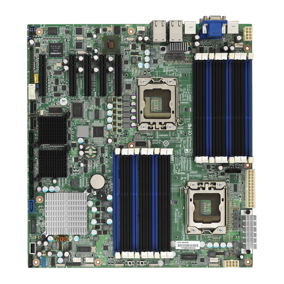
Page 10: Board Image
2.1- Board Image S7012 This picture is representative of the latest board revision available at the time of publishing. The board you receive may or may not look exactly like the above picture. http://www.tyan.com... -
Page 11: Block Diagram
2.2 - Block Diagram S7012 http://www.tyan.com... -
Page 12: Board Parts, Jumpers And Connectors
This diagram is representative of the latest board revision available at the time of publishing. The board you receive may not look exactly like the above diagram. Jumper Legend OPEN - Jumper OFF, without jumper cover CLOSED – Jumper ON, with jumper cover http://www.tyan.com... - Page 13 Pin 2-3 closed: Clear COM2 Switch Jumper Pin 1-2 closed: SIO to COM2 (Default) JP1/JP2 Pin 2-3 closed: BMC UART2 to COM2 LSI 1068E Device ID Select Jumper Pin 1-2 closed: (Default) Pin 2-3 closed: Device ID bit [0]=0b1 http://www.tyan.com...
- Page 14 (From left to right) SATA5/SATA4/SATA3/SATA2/SATA1/SATA0 http://www.tyan.com...
- Page 15 J34: USB Front Panel Header (Blue) Signal Signal USB D- USB D- USB D+ USB D+ SATA0/1/2/3/4/5: Serial ATA Connector Connects to the Serial ATA ready drives via the Serial ATA cable. SATA0: J30 SATA1: J29 SATA2: J26 SATA3: J23 SATA4: J22 SATA5: J21 http://www.tyan.com...
- Page 16 J6: Chassis Intrusion Header Signal Signal INTRUDER# http://www.tyan.com...
- Page 17 J41/J42/J43/J44/J45: 8-pin 4096 Fan Header (reserved for barebone) Signal Signal PWM1 +12V TACH1 TACH2 +12V PWM2 J41: Sys5 FAN & Sys10 FAN J42: Sys4 FAN & Sys9 FAN J43: Sys3 FAN & Sys8 FAN J44: Sys2 FAN & Sys7 FAN J45: Sys1 FAN & Sys6 FAN http://www.tyan.com...
- Page 18 USB3 http://www.tyan.com...
- Page 19 Clear CMOS Replace jumper cap to close Pin_1 and 2 Clear Reconnect power supply to AC source Power on system JP1/JP2: COM2 Switch Jumper Pin 1-2 Closed: SIO to COM2 (Default) Pin 2-3 Closed: BMC UART2 to COM2` http://www.tyan.com...
- Page 20 http://www.tyan.com...
- Page 21 Pin 1-2 Closed: LSI 1068E Device ID (Default) Pin 2-3 Closed: :LSI 1068E Device ID – Device ID bit [0] =0b1 J3: LSI 1068E Enable/Disable Jumper Pin 1-2 Closed: Enable LSI 1068E (Default) Pin 2-3 Closed: Disable LSI 1068E http://www.tyan.com...
-
Page 22: Installing The Processor And Heatsink
Please note that both processors of the same type and frequency are required for optimal system performance. NOTE: TYAN is not liable for damage as a result of operating an unsupported configuration. Follow these instructions to install your processor. - Page 23 Intel www.Intel.com Please refer to Intel’s website at The following diagram illustrates how to install heat sink onto the CPU of S7012. Place the heat sink on top of the CPU and secure it to the motherboard using four screws clockwise.
-
Page 24: Thermal Interface Material
CPU lid (applying too much will actually reduce the cooling). Note: Always check with the manufacturer of the heat sink & processor to ensure the Thermal Interface material is compatible with the processor & meets the manufacturer’s warranty requirements. http://www.tyan.com... -
Page 25: Finishing Installing The Heatsink
(which should already be attached to the heat sink) to the motherboard. The following diagram illustrates how to connect fans onto the motherboard. Once you have finished installing all the fans you can connect your drives (hard drives, CD-ROM drives, etc.) to your motherboard. http://www.tyan.com... -
Page 26: Tips On Installing Motherboard In Chassis
Some chassis’ include plastic studs instead of metal. Although the plastic studs are usable, TYAN recommends using metal studs with screws that will fasten the motherboard more securely in place. Below is a chart detailing what the most common motherboard studs look like and how they should be installed. -
Page 27: Installing The Memory
2.8 - Installing the Memory Before installing memory, ensure that the memory you have is compatible with the motherboard and processor. Check the TYAN Web site at: www.tyan.com for details of the type of memory recommended for your motherboard. The following diagram shows common types of DDR3 memory modules. - Page 28 Memory Installation Procedure Follow these instructions to install memory modules into the S7012. 1. Press the locking levers in the direction shown in the following illustration. Align the memory module with the socket. The memory module is keyed to fit only one way in the socket.
-
Page 29: Attaching Drive Cables
Connections for these drives are also very simple. There is no need to set Master/Slave jumpers on SATA drives. TYAN has supplied six SATA cables. If you are in need of other cables or power adapters please contact your place of purchase. -
Page 30: Installing Add-In Cards
YOU MUST ALWAYS unplug the power connector from the motherboard before performing system hardware NOTE changes. Otherwise you may damage the board and/or expansion device. http://www.tyan.com... -
Page 31: Installing I/O Shield
Use the pliers to grasp and twist the I/O port cap off the shield. Step 3. Repeat Step 1 & 2 to remove the I/O caps in accordance with your rear I/O configuration and then attach the I/O shield to the rear panel. http://www.tyan.com... -
Page 32: Connecting External Devices
2.12 - Connecting External Devices The following diagram will detail the rear port stack for this S7012 motherboard: Intel Intel 82576 82574 LAN4 LAN2 (share IPMI) VGA Port LAN3 LAN1 Serial Port USB x 2 USB x 2 NOTE: Peripheral devices can be plugged straight into any of these ports but software may be required to complete the installation. -
Page 33: Installing The Power Supply
2.13 - Installing the Power Supply There are three power connectors on your S7012. - 24-pin (PW3) - 8-pin (PW1, PW4) 1 x 24-pin 12V Power Connector (PW2) 2 x 8-pin 12V Power Connector (PW1, PW3) NOTE: Please be aware that ATX 2.x, ATX12V and ATXGES power supplies may not be compatible with the board and can damage the motherboard and/or CPU(s). - Page 34 NOTE http://www.tyan.com...
-
Page 35: Chapter 3: Bios Setup
To configure the advanced chipset features PCI/PnP To configure legacy Plug & Play or PCI settings Boot To configure system boot order Security To configure user and supervisor passwords Chipset To configure chipset management features Exit To exit setup utility http://www.tyan.com... - Page 36 Chipset section unless you are absolutely sure of what you are doing. The Chipset defaults have been carefully chosen either by TYAN or your system manufacturer for best performance and reliability. Even a seemingly small change to the Chipset setup options may cause the system to become unstable or unusable.
-
Page 37: Bios Main Menu
General Help F10 Save and Exit System Time [HH:MM:SS] ESC Exit System Date [MM:DD:YYYY] Feature Option Description Main Set the system time System Time HH : MM : SS System Date MM : DD : YYYY Set the system date http://www.tyan.com... -
Page 38: Advanced Menu
Section for Advanced ACPI ACPI Configuration Menu Item Configuration Section for Advanced AHCI AHCI Configuration Menu Item Configuration Hardware Health Configure/monitor the Menu Item Configuration Hardware Health IPMI configuration including IPMI 2.0 Configuration Menu Item server monitoring and event log http://www.tyan.com... - Page 39 PCI Express Configuration Menu Item Configure PCI Express Support Remote Access Configuration Menu Item Configure Remote Access Configure settings related to Trusted Computing Menu Item Trusted Computing Information Onboard Devices Onboard Devices and PCI Add- Menu Item Configuration on cards Enable/Disable http://www.tyan.com...
-
Page 40: Cpu Configuration
[Enabled] [Auto] C State package limit setting C1 Auto Demotion [Enabled] C3 Auto Demotion [Enabled] Feature Option Description CPU Configuration Manufacturer ® Intel Frequency Read only Displays information about CPU BCLK Speed Cache L1/L2/L3 Ratio Status Ratio Actual Value http://www.tyan.com... - Page 41 Intel TurboMode Tech frequency in specific condition. Enabled Disabled C-State: CPU idle is set to ® Intel C-STATE Tech C2/C3/C4 Enabled ® NOTE: C3 State and C6 State will appear when Intel SpeedStep Tech is set to [Disabled]. http://www.tyan.com...
- Page 42 When enabled, CPU will Enabled C1 Auto Demotion conditionally demote C3/C6/C7 requests to C1 based on uncore Disabled auto-demote information. When enabled, CPU will Enabled conditionally demote C6/C7 C3 Auto Demotion requests to C3 based on uncore Disabled auto-demote information. http://www.tyan.com...
- Page 43 Enable/Disable device write protection. Disabled Hard Disk Write Protect This will be effective only if device is Enabled accessed through BIOS. IDE Detect Time Out 0~35 Select the time out value for detecting (Sec) (at 5 interval) ATA/ATAPI device(s). http://www.tyan.com...
- Page 44 S.M.A.R.T (Self-Monitoring Analysis Auto and Reporting Technology) is a S.M.A.R.T. Disabled utility that monitors your disk status Enabled to predict hard disk failure. Enabled Enables 32-bit to maximize the IDE 32Bit Data Transfer hard disk data transfer rate. Disabled http://www.tyan.com...
- Page 45 POST Watchdog Mode OS: Start at OS Boot Power on: Start at power on Power ON Disabled When a chassis open event is detected, Chassis Intrusion the BIOS will record the event and issue a detection warning beep. Enabled http://www.tyan.com...
- Page 46 Enable or disable hotplug USB Enabled floppy support. A dummy FDD device is created that will be Hotplug USB FDD Support associated with the hotplugged Disabled FDD later. AUTO option creates this dummy device only Auto if there is no USB FDD present. http://www.tyan.com...
- Page 47 If Auto, USB devices less than 530 Floppy MB will be emulated as Floppy and remaining as hard drive. Forced Emulation Type Forced FDD FDD option can be used to force a HDD formatted drive to boot as FDD Hard Disk (Ex. ZIP drive). CDROM http://www.tyan.com...
- Page 48 Chipset Exit Advanced ACPI ACPI Settings Configuration settings Use this selection to Advanced ACPI Configuration configure additional Chipset ACPI Configuration ACPI options. ← → Select Screen ↑↓ Select Item Change Option General Help F10 Save and Exit ESC Exit http://www.tyan.com...
- Page 49 Enabled Include OEMB table pointer to AMI OEMB table R(X)SDT pointer lists. Disabled Enabled Enable or disable Headless Headless mode operation mode through ACPI. Disabled Enabled Enable or Disable the building of ACPI SRAT Table ACPI SRAT Table. Disabled http://www.tyan.com...
- Page 50 Resume feature, which is generally useless). Disabled Enable / Disable ACPI APIC SCI ACPI APIC SCI IRQ Enabled Enabled Enable/disable High Performance High Performance Event Timer Event Timer. Disabled FED00000h FED01000h HPET Memory Address Choose HPET Memory Address FED02000h FED03000h http://www.tyan.com...
- Page 51 AHCI Port4 [Not Detected] ESC Exit AHCI Port5 [Not Detected] Feature Option Description AHCI Configuration Enabled AHCI BIOS Support Enable for supporting AHCI. Disabled Some SATA CD/DVD in AHCI mode need AHCI CD/DVD Boot to wait ready longer. Time Out http://www.tyan.com...
- Page 52 AHCI Port0 Configuration Auto Select the type of device SATA Port0 connected to the system. Not Installed S.M.A.R.T (Self-Monitoring Enabled Analysis and Reporting S.M.A.R.T. Technology) is a utility that monitors your disk status to Disabled predict hard disk failure. http://www.tyan.com...
- Page 53 PWM Minimal Duty 40%-100% Cycle 30% Duty Cycle 30%-100% 0% Duty Cycle 0%-100% Manual Select chassis type to configure sensor 1x4 FAN event default status. Chassis Select Option [Manual] shows submenu to 1x8 FAN configure each sensor event. Auto http://www.tyan.com...
- Page 54 F10 Save and Exit ESC Exit SDR Monitoring Next Page SDR Monitoring Next Page Main Advanced PCI/PnP Boot Security Chipset Exit NAME READING STATUS Sys. 9 : xxxx RPM Sys. 10 : xxxx RPM Select [OK] to switch Available/Not Available [Cancel] http://www.tyan.com...
- Page 55 ESC Exit SDR Monitoring Next Page SDR Monitoring Next Page Main Advanced PCI/PnP Boot Security Chipset Exit NAME READING STATUS Sys. 9 : xxxx RPM Sys. 10 : xxxx RPM Read only. It can not be modified in user mode. http://www.tyan.com...
- Page 56 BMC Watch Dog Timer system if the operating system crashes or Action Power Down hangs. Power Cycle BMC Alert LED and BMC Alert LED and Beep On/Off Beep Enter IPMI FW key to upgrade IPMI or FW Key [xxxxxxx] iKVM function http://www.tyan.com...
- Page 57 PEF Support [Disabled] ← → Select Screen ↑↓ Select Item Change Option Tab Select Field General Help F10 Save and Exit ESC Exit Feature Option Description Set PEF Configuration Parameters Command Disabled PEF Support Enable or Disable PEF Support Enabled http://www.tyan.com...
- Page 58 Description LAN Configuration Channel Number Status Read only DHCP IPMI IP Source STATIC/DHCP IPMI DHCP (Read only) STATIC Current IP Address in BMC Read only Current Subnet Address in BMC Read only Current MAC Mask in BMC Read only http://www.tyan.com...
- Page 59 Intel VT-d Configuration ® Enable or disable Intel Virtualization Enabled Technology for Directed I/O (VT-d) support. VT-d support on Intel platforms provides the Intel VT-d capability to ensure improved isolation of Disabled I/O resources for greater reliability, security, and availability. http://www.tyan.com...
- Page 60 [Disabled] ← → Select Screen ↑↓ Select Item Change Option General Help F10 Save and Exit ESC Exit Feature Option Description PCI Express Configuration Enabled Active State Power- Enable/disable PCI Express L0s and Management L1 link power status. Disabled http://www.tyan.com...
- Page 61 COM2 Base Address, IRQ Read only 115200 8,n,1 57600 8,n,1 Serial Port Mode Select Serial Port settings. 38400 8, n, 1 19200 8,n,1 9600 8,n,1 None Select Flow Control for console Flow Control Hardware redirection. Software http://www.tyan.com...
- Page 62 VT-UTF8 Enabled VT-UTF8 Combo Key Enable VT-UTF8 Combination key Support Support for ANSI/VT100 terminals. Disabled No Delay Delay 1 Sec Sredir Memory Display Gives the delay in seconds to Delay display memory information Delay 2 Sec Delay 4 Sec http://www.tyan.com...
- Page 63 Report TPM Owner status Clearing the TPM is the process of returning the TPM to factory defaults. It is possible the platform owner will change when in this state. Are you sure you want to clear it? Cancel http://www.tyan.com...
- Page 64 Onboard VGA device. Enabled Enable/disable onboard LSI LSI 1068E Chip 1068E SAS controller. Disabled Enabled Lan (82575) Enable/disable Lan controller. Disabled Auto Lan (82574-1) Enable/disable Lan controller Enabled Lan (82574-2) Disabled Enabled Lan OP-ROM Executed Lan OP-ROM or not Disabled http://www.tyan.com...
-
Page 65: Pci Pnp Menu
When set to higher values, every PCI device PCI Latency Timer can conduct transactions for a longer time and thus improve the effective PCI bandwidth. Values in units of PCI clocks for PCI device latency timer register. http://www.tyan.com... - Page 66 Enabled: informs the PCI devices that an ISA graphics device is Enabled installed in the system so the card will function correctly. Enabled: BIOS uses PCI bus Disabled PCI IDE BusMaster mastering for reading / writing to IDE drives. Enabled http://www.tyan.com...
-
Page 67: Boot Menu
Bootup Num-Lock [On] Wait for ‘F1’ if Error [Enabled] ← → Select Screen Hit ‘DEL’ Message Display [Enabled] Interrupt 19 Capture [Enabled] ↑↓ Select Item Change Option Endless Boot [Disabled] General Help F10 Save and Exit ESC Exit http://www.tyan.com... - Page 68 Disabled Enabled Displays “Press DEL to run Setup” in Hit ‘DEL’ Message Display POST. Disabled Disabled Enabled: allows option ROMs to trap Interrupt 19 Capture interrupt 19. Enabled Disabled Enable/Disable endless loop boot from Endless Boot BBS table. Enabled http://www.tyan.com...
-
Page 69: Boot Device Priority
Change Option General Help F10 Save and Exit ESC Exit Feature Option Description Boot Device Priority xx,xxx-xxxxx:xxx Settings for boot priority. 1st Boot Device These can be customized 2nd Boot Device xx,xxx-xxxxx:xxx depending on your 3rd Boot Device preference. Disabled http://www.tyan.com... -
Page 70: Hard Disk Drives
1st Drive [xxxxxxxx] ← → Select Screen ↑↓ Select Item Change Option General Help F10 Save and Exit ESC Exit Feature Option Description Hard Disk Drives Specifies the boot xx,xxx-xxxxx:xxx 1st Drive sequence from the available Disabled devices. http://www.tyan.com... -
Page 71: Security Menu
User Password. When it is set to [Enabled], BIOS Disabled will issue a virus warning Boot Sector Virus Protection message and beep if a write to the boot sector or the partition Enabled table of the HDD is attempted. http://www.tyan.com... -
Page 72: Chipset Menu
WARNING: Setting wrong values in below sections may ← → Select Screen cause system to malfunction. ↑↓ Select Item CPU Bridge Configuration Enter Go to Sub Screen North Bridge Configuration General Help South Bridge Configuration F10 Save and Exit ME Subsystem Configuration ESC Exit http://www.tyan.com... - Page 73 Channel Mirroring Memory Mode space between channels Lockstep Lockstep: lockstep between channel 0 and 1 Sparing Spare: sparing mode Disabled ECC demand scrubbing Demand Scrubbing enabled / disabled Enabled Disabled ECC patrol scrubbing enabled Patrol Scrubbing / disabled Enabled http://www.tyan.com...
- Page 74 Crystal Beach/DMA [Disabled] Enter Go to Sub Screen General Help F10 Save and Exit ESC Exit Feature Option Description North Bridge Chipset Configuration NB Revision Read only Current QPI Frequency Disabled Crystal Beach/DMA Crystal Beach / DMA configuration Enabled http://www.tyan.com...
- Page 75 Enable or disable SMBUS controller Disabled 4~5 seconds 3~4 seconds SLP_S4# Min. Select Timing for SLP_S4# Assertion Width 2~3 seconds 1~2 seconds Power Off Restore on AC Power Configure how the system board Power On Loss responds to a power failure. Last State http://www.tyan.com...
- Page 76 ME Subsystem Configuration ← → Select Screen ME-HECI [Disabled] ↑↓ Select Item Enter Go to Sub Screen General Help F10 Save and Exit ESC Exit Feature Option Description South Bridge Chipset Configuration Enabled ME-HECI Enable or disable ME-HECI Disabled http://www.tyan.com...
-
Page 77: Exit Menu
Use this option to load default performance setup values. Use this option when system CMOS values have been corrupted or modified incorrectly. Load Failsafe Defaults Use this option to load all default failsafe setup values. Use this option when troubleshooting. http://www.tyan.com... - Page 78 NOTE http://www.tyan.com...
-
Page 79: Chapter 4: Diagnostics
BIOS flash failure, you must contact your dealer for a replacement BIOS. There are no exceptions. TYAN does not have a policy for replacing BIOS chips directly with end users. In no event will TYAN be held responsible for damages done by the end user. -
Page 80: Amibios Post Code
ADM module for initialization. Initialize language and font modules for ADM. Activate ADM module. Initializes the silent boot module. Set the window for displaying text information. Displaying sign-on message, CPU information, setup key message, and any OEM specific information. http://www.tyan.com... - Page 81 Wait for user input at config display if needed. Uninstall POST INT1Ch vector and INT09h vector. Deinitializes the ADM module. Prepare BBS for Int 19 boot. End of POST initialization of chipset registers. Save system context for ACPI. Passes control to OS Loader (typically INT19h). http://www.tyan.com...
- Page 82 NOTE http://www.tyan.com...
-
Page 83: Glossary
While this improves system performance --- reading to or writing from a disk drive a single time is much faster than doing so repeatedly --- there is also the possibility of losing your data should the system crash. Information stored in a buffer is temporarily stored, not permanently saved. http://www.tyan.com... - Page 84 DMA (Direct Memory Access): channels that are similar to IRQs. DMA channels allow hardware devices (like soundcards or keyboards) to access the main memory without involving the CPU. This frees up CPU resources for other tasks. As with http://www.tyan.com...
- Page 85 EEPROM (Electrically Erasable Programmable ROM): also called Flash BIOS, is a ROM chip which can, unlike normal ROM, be updated. This allows you to keep up with changes in the BIOS programs without having to buy a new chip. TYAN’s BIOS updates can be found at http://www.tyan.com ESCD (Extended System Configuration Data): a format for storing information about Plug-n-Play devices in the system BIOS.
- Page 86 In this configuration, SRAM requests are pipelined, which means that larger packets of data are sent to the memory at one time, and acted upon quickly. This type of SRAM operates at bus speeds higher than 66MHz. http://www.tyan.com...
- Page 87 SDRAM (Synchronous Dynamic RAM): called as such because it can keep two sets of memory addresses open simultaneously. By transferring data alternately from one set of addresses and then the other, SDRAM cuts down on the delays http://www.tyan.com...
- Page 88 CPUs without damaging the sensitive CPU pins. The CPU is lightly placed in an open ZIF socket, and a lever is pulled down. This shift the processor over and down, guiding into the board and locking it into place. http://www.tyan.com...
-
Page 89: Technical Support
Return Merchandise Authorization (RMA) number. The RMA number should be prominently displayed on the outside of the shipping carton and the package should be mailed prepaid. TYAN will pay to have the board shipped back to you. - Page 90 Danger of explosion if battery is incorrectly replaced. Replace only with the same or equivalent type recommended by manufacturer. Dispose of used battery according to manufacturer instructions and in accordance with your local regulations. Document #: D1994-100 http://www.tyan.com...
Need help?
Do you have a question about the S7012 and is the answer not in the manual?
Questions and answers