Table of Contents
Advertisement
Quick Links
Проконсультироваться и купить данное оборудование вы можете в компании «АНД-Системс»
адрес: 125480, г.Москва, ул.Туристская, д.33/1; site: https://andpro.ru тел: +7 (495) 545-4870 email: info@andpro.ru
Copyright
Copyright © 2018 MITAC COMPUTING TECHNOLOGY CORPORATION. All rights
reserved. No part of this manual may be reproduced or translated without prior
written consent from MITAC COMPUTING TECHNOLOGY CORPORATION.
Trademark
All registered and unregistered trademarks and company names contained in this
manual are property of their respective owners including, but not limited to the
following.
®
TYAN
is a trademark of MITAC COMPUTING TECHNOLOGY CORPORATION.
Intel
®
is a trademark of Intel
AMI, AMI BIOS are trademarks of AMI Technologies.
Microsoft
®
, Windows
®
Nuvoton
is a trademark of Nuvoton Technology Corporation.
Notice
Information contained in this document is furnished by MITAC COMPUTING
TECHNOLOGY CORPORATION and has been reviewed for accuracy and reliability
prior to printing. MITAC assumes no liability whatsoever, and disclaims any express
or implied warranty, relating to sale and/or use of TYAN
or warranties relating to fitness for a particular purpose or merchantability. MITAC
retains the right to make changes to product descriptions and/or specifications at
any time, without notice. In no event will MITAC be held liable for any direct or
indirect, incidental or consequential damage, loss of use, loss of data or other
malady resulting from errors or inaccuracies of information contained in this
document.
При обращении используйте промокод AND-PDF и получите скидку.
S7103
Version 1.0c
®
Corporation.
®
are trademarks of Microsoft Corporation.
http://www.tyan.com
®
products including liability
1
Advertisement
Table of Contents

Related Manuals for TYAN S7103


Summary of Contents for TYAN S7103
- Page 1 Information contained in this document is furnished by MITAC COMPUTING TECHNOLOGY CORPORATION and has been reviewed for accuracy and reliability prior to printing. MITAC assumes no liability whatsoever, and disclaims any express or implied warranty, relating to sale and/or use of TYAN ® products including liability or warranties relating to fitness for a particular purpose or merchantability.
- Page 2 http://www.tyan.com...
-
Page 3: Table Of Contents
3.9 Save & Exit ..................146 Chapter 4: Diagnostics ................149 4.1 Flash Utility ..................149 4.2 AMIBIOS Post Code (Aptio) ............150 Appendix: Fan and Temp Sensors............157 Glossary ....................161 Technical Support .................. 167 http://www.tyan.com... -
Page 4: Before You Begin
2 x CPU clip for Narrow Non-Fabric CPU Carrier 2 x SATA Cable 1 x Rear IO Shield 1 x S7103 Quick reference guide ® 1 x TYAN Driver’s and Utilities DVD IMPORTANT NOTE: Sales sample may not come with the accessory listed above. -
Page 5: Chapter 1: Instruction
32 and 64-bit computing, high-bandwidth memory design, and lightning- fast PCI-E bus implementation. The S7103 not only empowers you in today’s demanding IT environment but also offers a smooth path for future application upgradeability. All of these rich feature sets provides the S7103 with the power and flexibility to meet demanding requirements for today’s IT environments. - Page 6 & system environment System Monitoring Monitors voltage for CPU, memory, Voltage chipset & power supply Over temperature warning indicator, Fan & PSU fail LED indicator Others Watchdog timer support Server Management AST2500 iKVM Feature IPMI 2.0 compliant baseboard http://www.tyan.com...
- Page 7 Please refer to our AVL support lists. Motherboard (1) S7103 Motherboard Package Contains Manual (1) Quick Installation Guide Installation CD (1) TYAN Device Driver CD TYAN S7103 (S7103WGM2NR) Socket Type / Q'ty LGA3647/ (2) Supported CPU Intel Xeon Scalable Processor Series...
- Page 8 Connector type D-Sub 15-pin Graphic Resolution Up to 1920x1200 Chipset Aspeed AST2500 (2) USB3.0 ports (via cable), (2) USB3.0 ports (at rear), (1) Type-A USB3.0 port Input /Output (1) DB-9 COM Connector (1) D-Sub 15-pin VGA port (at rear) http://www.tyan.com...
- Page 9 SMBIOS 3.0/PnP/Wake on LAN, Boot from USB device/PXE via BIOS Feature LAN/Storage, User Configurable FAN PWM Duty Cycle, Console Redirection, ACPI sleeping states S0,S1,S5 Form Factor EATX Physical Dimension Board Dimension 12"x13" (305x330mm) FCC (DoC) Class A Regulation CE (DoC) Class A http://www.tyan.com...
- Page 10 OS supported list lists. Motherboard (1) S7103 Motherboard Package Contains Manual (1) Quick Installation Guide Installation CD (1) TYAN Device Driver CD TYAN S7103 (S7103GM4NR-2F-L2) Socket Type / Q'ty LGA3647/ (2) Supported CPU Intel Xeon Scalable Processor Series Thermal Design...
- Page 11 & system environment Monitors voltage for CPU, memory, System Monitoring Voltage chipset & power supply Over temperature warning indicator, Fan & PSU fail LED indicator Others Watchdog timer support AST2500 iKVM IPMI 2.0 compliant baseboard Server Management Feature management controller (BMC), http://www.tyan.com...
- Page 12 OS supported list lists. Motherboard (1) S7103 Motherboard Package Contains Manual (1) Quick Installation Guide Installation CD (1) TYAN Device Driver CD TYAN S7103 (S7103WGM4NR-2F-L2) Socket Type / Q'ty LGA3647/ (2) Supported CPU Intel Xeon Scalable Processor Series Thermal Design...
- Page 13 (2) SATA/SATA-DOM Controller Intel C622 sSATA Speed 6.0 Gb/s RAID 0/1/10/5 (Intel RAID RSTe) Connector type D-Sub 15-pin Graphic Resolution Up to 1920x1200 Chipset Aspeed AST2500 (2) USB3.0 ports (via cable), (2) Input /Output USB3.0 ports (at rear), (1) Type-A http://www.tyan.com...
- Page 14 AMI, 32MB Hardware Monitor, ACPI 5.0, SMBIOS 3.0/PnP/Wake on LAN, Boot from USB device/PXE via BIOS Feature LAN/Storage, User Configurable FAN PWM Duty Cycle, Console Redirection, ACPI sleeping states S0,S1,S5 Form Factor EATX Physical Dimension Board Dimension 12"x13" (305x330mm) http://www.tyan.com...
- Page 15 OS supported list lists. Motherboard (1) S7103 Motherboard Package Contains Manual (1) Quick Installation Guide Installation CD (1) TYAN Device Driver CD TYAN S7103 (S7103GM2NR-2F-L2) Socket Type / Q'ty LGA3647/ (2) Supported CPU Intel Xeon Scalable Processor Series Thermal Design...
- Page 16 Aspeed AST2500 Total (1) 2 x 10-pin headers Monitors temperature for CPU & Temperature memory & system environment System Monitoring Monitors voltage for CPU, memory, Voltage chipset & power supply Over temperature warning indicator, Fan & PSU fail LED indicator http://www.tyan.com...
- Page 17 OS supported list lists. Motherboard (1) S7103 Motherboard Package Contains Manual (1) Quick Installation Guide Installation CD (1) TYAN Device Driver CD TYAN S7103 (S7103WGM2NR-2F-L2) Socket Type / Q'ty LGA3647/ (2) Processor Supported CPU Intel Xeon Scalable Processor Series http://www.tyan.com...
- Page 18 (2) Mini-SAS (8-ports) Controller Intel C622 Storage SATA Speed 6.0 Gb/s RAID 0/1/10/5 (Intel RAID RSTe) (1) Mini-SAS (4-ports), Connector (2) SATA/SATA-DOM Controller Intel C622 sSATA Speed 6.0 Gb/s RAID 0/1/10/5 (Intel RAID RSTe) Graphic Connector type D-Sub 15-pin http://www.tyan.com...
- Page 19 Server Management virtual hub 24-bit high quality video AST2500 IPMI compression, 10/100/1000 Mb/s Feature MAC interface Brand / ROM size AMI, 32MB Hardware Monitor, ACPI 5.0, BIOS SMBIOS 3.0/PnP/Wake on LAN, Feature Boot from USB device/PXE via LAN/Storage, User Configurable http://www.tyan.com...
-
Page 20: Software Specifications
OS supported list lists. Motherboard (1) S7103 Motherboard Package Contains Manual (1) Quick Installation Guide Installation CD (1) TYAN Device Driver CD 1.3 Software Specifications ® For OS (operation system) support, please check with TYAN support for latest information. http://www.tyan.com... -
Page 21: Chapter 2: Board Installation
To avoid damaging the motherboard and associated components, do not use torque force greater than 5~7 kgf/cm (4.35 ~ 6.09 lb/in) on each mounting screw for motherboard installation. Do not apply power to the board if it has been damaged. http://www.tyan.com... -
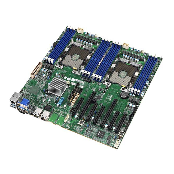
Page 22: Board Image
2.1 Board Image S7103WGM4NR-2F-L2 This picture is representative of the latest board revision available at the time of publishing. The board you receive may not look exactly like the above picture. http://www.tyan.com... -
Page 23: Block Diagram
2.2 Block Diagram S7103 Block Diagram http://www.tyan.com... -
Page 24: Mainboard Mechanical Drawing
2.3 Mainboard Mechanical Drawing http://www.tyan.com... -
Page 25: Board Parts, Jumpers And Connectors
The board you receive may not look exactly like the above diagram. But for the DIMM number please refer to the above placement for memory installation. For the latest board revision, please visit our web site at http://www.tyan.com. http://www.tyan.com... - Page 26 (J1) 30. SATA3.0 Mini (4 in 1) Connector 12. SYS_FAN_5 Connector (SYS_FAN_5) (PCH_SATA2) 31. SATA3.0 Mini (4 in 1) Connector 13. TYAN Module Header (DBG_HD1) (PCH_SATA1) 14. SATA DOM Connector 32. ATX 24-pin Power Connector (PW1) (SSATA_DOM0) 33. SSATA3.0 Mini (4 in 1) Connector 15.
- Page 27 PCIE Slots (x8) (PCIe_slot3) PCIE Slots (x16) (PCIe_slot2) PCIE Slots (x8) (PCIe_slot1) Jumper Legend OPEN - Jumper OFF Without jumper cover CLOSED - Jumper ON With jumper cover http://www.tyan.com...
- Page 28 FPIO_1: Front Panel Header Signal Signal PWRLED+ VCC3_AUX IDLED+ PWRLED- IDLED- HDDLED+ SYS_FAULT1- HEELED- SYS_FAULT2- PWR_SW# LAN0_LED+ LAN0_LED- RESET_SW# SMBDATA SMBCLK IDLED_SW# INTRUSION# SYS_AIR_INLET LAN1_LED+ NMI_SW# LAN1_LED- J20: Chassis Intrusion Header Signal Signal PCH_INTRUDER_N SW3: ID LED Switch Button Signal Signal FP_IDLED_BTN_N http://www.tyan.com...
- Page 29 PSMI1: PSMI Connector Signal Signal SMB_CLK SMB_DAT SMB_ALERT# VCC3 DBG_HD1: TYAN Module Header Signal Signal VCC3 FRAME LAD0 LAD1 RESET# LAD2 LAD3 SERIRQ PRSNT# 3VSB GPIO1 GPIO2 IPMB_HD1: IPMB Pin Header Signal Signal BMC_SMB_DATA BMC_SMB_CLK USB3_FPIO1: USB3.0 Header Signal Signal...
- Page 30 SDIN DATA SDOUT SLOAD SCLOCK VCC3_AUX HDD_FAULT SSATA_DOM0 / SSATA_DOM1: SSATA DOM Connector Signal Signal sSATA6G_RX_P4 sSATA6G_TX_P4 sSATA6G_TX_N4 VCC5 sSATA6G_RX_N4 FPIO_VGA2: Front Panel VGA Header (not available for S7103GM2NR) Signal Signal VGA_5V HD_VGA_R HD_VGA_G HD_VGA_B HD_VGA_DAT HD_VGA_HS HD_VGA_CLK HD_VGA_VS http://www.tyan.com...
- Page 31 Signal Signal BMC_COM2_TXD TXD_2 BMC_COM5_TXD Pin1-2 closed: BMC COM2 Debug (Default) Pin2-3 closed: BMC COM5 Debug 3PHD2: ME Recovery Mode Jumper Signal Signal FM_ME_RCVR_N Rpd 49.9 om Pin1-2 closed: Normal Mode (Default) Pin2-3 closed: ME In Force Update Mode http://www.tyan.com...
-
Page 32: Installing The Processor And Heat Sink
Specifications on page 5. Check our website at http://www.tyan.com for latest processor support. NOTE: MITAC TYAN is not liable for damage as a result of operating an unsupported configuration. Processor Installation for LGA3647 Socket Follow the steps below to install the processors and heat sinks. NOTE: Please save and replace the CPU protection cap when returning for service. - Page 33 Save and replace the CPU cover if the processor is removed from its socket. Align the heatsink with the CPU socket by the guide pins and make sure the gold arrow is located in the correct direction. Then place the heatsink onto the top of the CPU socket. http://www.tyan.com...
- Page 34 NOTE: When disassembling the heatsink, loosen the screws in reverse order (4321). NOTE: Always check with the manufacturer of the heat sink & processor to ensure that the thermal interface material is compatible with the processor and meets the manufacturer’s warranty requirements. http://www.tyan.com...
-
Page 35: Tips On Installing Motherboard In Chassis
Some chassis include plastic studs instead of metal. Although the plastic studs are usable, MITAC recommends using metal studs with screws that will fasten the motherboard more securely in place. http://www.tyan.com... - Page 36 Below is a chart detailing what the most common motherboard studs look like and how they should be installed. http://www.tyan.com...
-
Page 37: Installing The Memory
2.8 Installing the Memory Before installing memory, ensure that the memory you have is compatible with the motherboard and processor. Check the TYAN Web site at http://www.tyan.com details of the type of memory recommended for your motherboard. Supports single/dual rank memory ... - Page 38 √ √ √ P0_MCO_DIM_CH_D0 √ √ √ P0_MCO_DIM_CH_E0 √ √ P0_MCO_DIM_CH_F0 √ P1_MCO_DIM_CH_A0 √ √ √ √ √ √ P1_MCO_DIM_CH_B0 √ √ √ √ √ P1_MCO_DIM_CH_C0 √ √ √ √ P1_MCO_DIM_CH_D0 √ √ √ P1_MCO_DIM_CH_E0 √ √ P1_MCO_DIM_CH_F0 √ http://www.tyan.com...
- Page 39 Memory Installation Procedure Follow these instructions to install memory modules into the S7103. Unlock the clips as shown in the illustration. Insert the memory module firmly into the socket by gently pressing down until it sits flush with the socket.
-
Page 40: Attaching Drive Cables
2.9 Attaching Drive Cables Attaching Serial ATA Cables S7103 is equipped with six (6) Serial ATA (SATA) channel. Connections for the drives are very simple. There is no need to set Master/Slave jumpers on SATA drives. If you are in need of SATA/SAS cables or power adapters please contact your place of purchase. -
Page 41: Installing Add-In Cards
Doing so allows air to circulate within the chassis more easily, thus improving cooling for all installed devices. NOTE: You must always unplug the power connector to the motherboard before performing system hardware changes to avoid damaging the board or expansion device. http://www.tyan.com... -
Page 42: Connecting External Devices
10/100/1000 Mbps LAN Link/Activity LED Scheme Left LED Right LED Link Green 10 Mbps Active Blinking Green Solid Green Link Green 100 Mbps Solid Green Active Blinking Green Solid Yellow Link Green 1000 Mbps Solid Yellow Active Blinking Green No Link http://www.tyan.com... -
Page 43: Installing The Power Supply
2.13 Installing the Power Supply There are three (3) power connectors on your S7103 motherboard. The S7103 supports EPS 12V power supply. PW1: ATX 24-pin Main Power Connector Signal Signal VCC3 VCC3 VCC3 -12V VCC5 PS_ON# VCC5 PWR_OK 5VSB VCC5... -
Page 44: Finishing Up
In the rare circumstance that you have experienced difficulty, you can find help by asking your vendor for assistance. If they are not available for assistance, please find setup information and documentation online at our website or by calling your vendor’s support line. http://www.tyan.com... -
Page 45: Chapter 3: Bios Setup
The table below shows how to navigate in the setup program using the keyboard. Function Left/Right Arrow Keys Change from one menu to the next Up/Down Arrow Keys Move between selections Enter Open highlighted section PgUp/PgDn Keys Change pages Change options Exit http://www.tyan.com... - Page 46 The following pages provide the details of BIOS menu. Please be noticed that the BIOS menu are continually changing due to the BIOS updating. The BIOS menu provided are the most updated ones when this manual is written. Please visit TYAN’s website at http://www.tyan.com for the information of BIOS updating.
-
Page 47: Main Menu
Note that the options listed below are for options that can directly be changed within the Main Setup screen. System Date Set the Date. Use Tab to switch between Date elements. Default Ranges: Year: 2005-2099 Months: 1-12 Days: dependent on month System Time Set the Time. Use Tab to switch between Time elements. http://www.tyan.com... -
Page 48: Advanced Menu
Intel® Virtual RAID on CPU This formset allows the user to manage Intel® Virtual RAID on CPU. Trusted Computing Trusted Computing Settings. ACPI Settings System ACPI Parameters. Hardware Health Configuration Hardware health Configuration Parameters. Onboard Device Configuration Onboard Device Configuration. http://www.tyan.com... - Page 49 Option ROM Dispatch Policy. PCI Subsystem Settings PCI, PCI-X and PCI Express Settings. Network Stack Configuration Network Stack Settings. CSM Configuration CSM configuration: Enable/Disable, Option ROM execution settings, etc. USB Configuration USB Configuration Parameters. NVDIMM ADR Configuration NVDIMM ADR Configuration. http://www.tyan.com...
- Page 50 Select Advanced Network Stack Configuration Network Stack [Enabled] Step 3. Save changes and reboot. iSCSI Initiator Name The worldwide unique name of iSCSI Initiator. Only IQN format is accepted. Enter [iqn.xxx]. xxx ranges from 4 to 223. http://www.tyan.com...
- Page 51 3.3.1.1 Add an Attempt Read only. NOTE: Only LAN1 supports iSCSI function. http://www.tyan.com...
- Page 52 IP4 / IP6 / Autoconfigure Connection Retry Count The minimum value is 0 and the maximum is 16. 0 means no retry. Connection Establishing Timeout The timeout value in milliseconds. The minimum value is 100 milliseconds and the maximum is 20 seconds. http://www.tyan.com...
- Page 53 Target Port Target Port. Boot LUN Hexadecimal representation of the LU number. Examples are: 4752-3A4F-6b7e- 3F99, 6734-9-156f-127, 4186-9. Authentication Type Authentication method: CHAP, Kerberos, or None. CHAP / None Save Changes Must reboot system manually for changes to take place. http://www.tyan.com...
- Page 54 3.3.1.2 Delete Attempts Attempt 1 MAC: 34:12:78:56:00:00, PFA: Bus 1/ Dev 0 / Func 0, iSCSI mode: Disabled, IP version: IP4. Disabled / Enabled Commit Changes and Exit Commit Changes and Exit. Discard Changes and Exit Discard Changes and Exit. http://www.tyan.com...
- Page 55 Change the order of Attempts using +/- keys. Use arrow keys to select the attempt then press +/- to move the attempt up/down in the attempt order list. Attempt 1 / Attempt # Commit Changes and Exit Commit Changes and Exit. Discard Changes and Exit Discard Changes and Exit. http://www.tyan.com...
- Page 56 Suppose the card is installed in CPU0 Slot 3, then Intel® VMD for Volume Management Device for PStack0 will be set to [Enabled]. Step 3. Save changes and reboot. All Intel VMD Controllers Select to see more information about the Intel VMD Controllers. http://www.tyan.com...
- Page 57 3.3.2.1 All Intel VMD Controllers Create RAID Volume This page allows you to create a RAID volume. Non-RAID Physical Disks Read only. http://www.tyan.com...
- Page 58 Enable RAID spanned over VMD Controllers Enter RAID spanned over VMD Controllers. blank / X Port 0, VMD0, INTEL SSDPE2MD400G4 X – to Select Disk. blank / X Port 1, VMD1, INTEL SSDPEDME400G4 X – to Select Disk. blank / X http://www.tyan.com...
- Page 59 Create a volume with the settings specified above. NOTE: For Create Volume to be configurable, the following items Enable RAID spanned over VMD Controllers, Port 0, VMD0, INTEL SSDPE2MD400G4 and Port 1, VMD1, INTEL SSDPEDME400G4 must be set to [X]. http://www.tyan.com...
- Page 60 3.3.2.1.1.1 Create Volume Press ‘y’ to create, ‘n’ to discard. Volume0, RAID0(Stripe), 708.0GB, Normal Select to see more information about the RAID volume. http://www.tyan.com...
- Page 61 3.3.2.1.1.1.1 Volume0, RAID0(Stripe), 708.0GB, Normal Read only. http://www.tyan.com...
- Page 62 3.3.2.1.1.1.1.1 Delete Delete the RAID Volume Deleting a volume will reset the disks to non-RAID. Yes / No http://www.tyan.com...
- Page 63 3.3.2.1.2 Port 0, VMD0, INTEL SSDPE2MD400G4 SN: xxxx, … Port 1, VMD1, INTEL SSDPEDMD400G4 SN: xxxx, …. Read only. http://www.tyan.com...
- Page 64 3.3.3 Trusted Computing Security Device Support Enables or Disables BIOS support for security device. O.S. will not show Security Device. TCG EFI protocol and INT1A interface will not be available. Enabled / Disabled http://www.tyan.com...
- Page 65 3.3.4 ACPI Settings Enable ACPI Auto Configuration Enable or disable BIOS ACPI Auto Configuration. Disabled / Enabled Enable Hibernation Enable or disable System ability to Hibernate (OS/S4 Sleep State). This option may not be effective with some OS. Disabled / Enabled http://www.tyan.com...
- Page 66 Auto Fan Control Auto Fan Control Help. Disabled / Enabled PWM Minimal Duty Cycle PWM Minimal Duty Cycle. 15% Duty Cycle / 30% Duty Cycle / 45% Duty Cycle BMC Alert Beep Enable/Disable BMC Alert Beep. Off / On http://www.tyan.com...
- Page 67 5.3.5.1 Sensor Data Register Monitoring When you enter the Sensor Data Register Monitoring submenu, you will see the following dialog window pop out. Please wait 8~10 seconds. NOTE: SDR can not be modified. Read only. http://www.tyan.com...
- Page 68 3.3.6 Onboard Device Configuration Chassis Intrusion detect Enabled: when a chassis open event is detected, the BIOS will record the event. Disabled / Enabled NMI Function Enable or Disable NMI function. Disabled / Enabled http://www.tyan.com...
- Page 69 3.3.7 AST2500 Super IO Configuration Super IO Chip Read only. http://www.tyan.com...
- Page 70 / IO=3F8h, IRQ=3, 4, 5, 6, 7, 9, 10, 11, 12; / IO=2F8h; IRQ=3, 4, 5, 6, 7, 9, 10, 11, 12; / IO=3E8h, IRQ=3, 4, 5, 6, 7, 9, 10, 11, 12; / IO=2E8h, IRQ=3, 4, 5, 6, 7, 9, 10, 11, 12; http://www.tyan.com...
- Page 71 Select 0-23. For example enter 3 for 3am and 15 for 3pm. Wake up minute Select 0-59 for Minute. Wake up second Select 0-59 for Second. When Wake system from S5 is set to [Dynamic Time] Wake up Minute increase 1-5. http://www.tyan.com...
- Page 72 Console redirection enable or disable. Disabled / Enabled Legacy Console Redirection Settings Legacy Console redirection settings. Console Redirection Settings The settings specify how the host computer (which the user is using) will exchange data. Both computers should have the same or compatible settings. http://www.tyan.com...
- Page 73 1’s in the data bits is odd. Mark: parity bit is always 1. Space: parity bit is always 0. Mark and Space parity do not allow for error detection. None / Even / Odd / Mark / Space http://www.tyan.com...
- Page 74 Redirection after BIOS POST The settings specify if BootLoader is selected than Legacy console redirection is disabled before booting to Legacy OS. Default value is Always Enable which means Legacy Console Redirection is enabled for Legacy OS. Always Enable / BootLoader http://www.tyan.com...
- Page 75 3.3.9.2 Legacy Console Redirection Settings Legacy Serial Redirection Port Select a COM port to display redirection of Legacy OS and Legacy OPROM Messages. COM1 / COM2 http://www.tyan.com...
- Page 76 VT-UTF8 / VT100 / VT100+ / ANSI Bits per Second Select serial port transmission speed. The speed must be matched on the other side. Long or noisy lines may require lower speeds. 115200 / 9600 / 19200 / 57600 http://www.tyan.com...
- Page 77 ‘start’ signal can be sent to restart the flow. Hardware flow control uses two wires to send start/stop signal. None / Hardware RTS/CTS / Software Xon/Xoff Data Bits / Parity / Stop Bits Read only. http://www.tyan.com...
- Page 78 Select onboard LAN1 Option ROM type. PXE / iSCSI Onboard LAN2 (I350) Enable or disable onboard LAN2 Option ROM. Disabled / Enabled PCIE_1 Empty / PCIE_5 Empty Enable or Disable Option ROM execution for selected Slot. Disabled / Enabled http://www.tyan.com...
- Page 79 Enables or Disables 64bit capable Devices to be Decoded in Above 4G Address Space (Only if System Supports 64 bit PCI Decoding). Enabled / Disabled SR-IOV Support If system has SR-IOV capable PCIe Devices, this option Enables or Disables Single Root IO Virtualization Support. Enabled / Disabled http://www.tyan.com...
- Page 80 Enable Ipv4 HTTP Boot Support. If disabled IPV4 HTTP boot option will not be created. Disabled / Enabled Ipv6 PXE Support Enable Ipv6 PXE Boot Support. If disabled IPV6 PXE boot option will not be created. Disabled / Enabled http://www.tyan.com...
- Page 81 Enable Ipv6 HTTP Boot Support. If disabled IPV6 HTTP boot option will not be created. Disabled / Enabled PXE boot wait time Wait time to press ESC key to abort the PXE boot. Media detect count Number of times presence of media will be checked. http://www.tyan.com...
- Page 82 UEFI and Legacy / Legacy only / UEFI only Network Controls the execution of UEFI and Legacy PXE OpROM. Legacy / Do not launch / UEFI Storage Controls the execution of UEFI and Legacy Storage OpROM. Legacy / Do not launch / UEFI http://www.tyan.com...
- Page 83 Video Controls the execution of UEFI and Legacy Video OpROM Legacy / Do not launch / UEFI Other PCI Devices Determines OpROM execution policy for devices other than Network, Storage, or Video. Legacy / Do not launch / UEFI http://www.tyan.com...
- Page 84 XHCI Hand-off This is a workaround for OSes without XHCI hand-off support. The XHCI ownership change should be claimed by XHCI driver. Enabled / Disabled USB Mass Storage Driver Support Enable/Disable USB Mass Storage Driver Support. Enabled / Disabled http://www.tyan.com...
- Page 85 Mass storage device emulation type. ‘Auto’ enumerates devices according to their media format. Optical drives are emulated as ‘CDROM’, drives with no media will be emulated according to a drive type. Auto / Floppy / Forced FDD / Hard Disk / CD-OM http://www.tyan.com...
- Page 86 3.3.15 NVDIMM ADR Configuration Assert ADR on Reset Assert ADR on Reset. Disabled / Enabled Assert ADR on Shutdown Assert ADR on Shutdown. Disabled / Enabled http://www.tyan.com...
-
Page 87: Platform Configuration
3.4 Platform Configuration PCH Configuration Displays and provides option to change the PCH Settings. Server ME Configuration Configure Server ME Technology Parameters. http://www.tyan.com... - Page 88 PCH sSATA Configuration sSATA devices and settings. USB Configuration USB Configuration Settings. PCH DFX Configuration PCH DFX Configuration Options. PCH state after G3 Select S0/S5 for ACPI state after a G3. S0 / Onboard / S5 / Leave power state unchanged http://www.tyan.com...
- Page 89 L1 Substates PCI Express L1 Substates settings. Disabled / L1.1 / L1.2 / L1.1 & L1.2 PCIe Speed Configure PCIe Speed. Auto / Gen1 / Gen2 / Gen3 Max Payload Size PCIE Max Payload Size Selection. MPL128B / MPL256B http://www.tyan.com...
- Page 90 Determines how SATA controller(s) operate. AHCI / RAID Port 0 Enable or Disable SATA Port. Disabled / Enabled Hot Plug Designates this port as Hot Pluggable. Disabled / Enabled Configure as eSATA Configures port as External SATA (eSATA). Disabled / Enabled http://www.tyan.com...
- Page 91 Identify the SATA port is connected to Solid State Drive or Hard disk Drive. Hard Disk Drive / Solid State Drive SATA Topology Identify the SATA Topology if it is Default or ISATA or Flex or DirectConnect or M2. Unknown / ISATA / Direct Connect / Flex / M2 http://www.tyan.com...
- Page 92 Determines how SATA controller(s) operate. AHCI / RAID Port 0 Enable or Disable SATA Port. Disabled / Enabled Hot Plug Designates this port as Hot Pluggable. Disabled / Enabled Configure as eSATA Configures port as External SATA (eSATA). Disabled / Enabled http://www.tyan.com...
- Page 93 Identify the SATA port is connected to Solid State Drive or Hard disk Drive. Hard Disk Drive / Solid State Drive SATA Topology Identify the SATA Topology if it is Default or ISATA or Flex or DirectConnect or M2. Unknown / ISATA / Direct Connect / Flex / M2 http://www.tyan.com...
- Page 94 3.4.1.4 USB Configuration XHCI Idle L1 Enabled XHCI Idle L1. Disabled to workaround USB3 hot plug will fail after 1 hot plug removal. Please put the system to G3 for the new settings to take effect. Enabled / Disabled http://www.tyan.com...
- Page 95 Enabled / Disabled Enable/Disable ADR Timer Held-off for DEBUG PURPOSES ONLY!. Enabled / Held-off ADR timer expire time Select proper ADR timer value: 25uS, 50uS, 100uS or 0. 25 uS / 50 uS / 100 uS / 0 us http://www.tyan.com...
- Page 96 ADR timer multiplier Select proper ADR timer multiplier: x1, 8, 24, 40, 56, 64, 72, 80, 88, 96. x1 / x8 / x24 / x40 / x56 / x64 / x72 / x80 / x88 / x96 http://www.tyan.com...
- Page 97 3.4.2 Miscellaneous Configuration Active Video Select active video type. Auto / Onboard Device / Offboard Device http://www.tyan.com...
- Page 98 3.4.3 Server ME Configuration Read only. http://www.tyan.com...
-
Page 99: Socket Configuration
Displays and provides option to change the UPI Settings. Memory Configuration Displays and provides option to change the Memory Settings. IIO Configuration Displays and provides option to change the IIO Settings. Advanced Power Management Configuration Displays and provides option to change the Power Management Settings. http://www.tyan.com... - Page 100 This should be enabled in order to boot legacy OSes that cannot support CPUs with extended CPUID functions. Disabled / Enabled Execute Disable Bit When disabled, forces the XD feature flag to always return 0. Disabled / Enabled Enable Intel® TXT Enables Intel® TXT. Disabled / Enabled http://www.tyan.com...
- Page 101 Lock or Unlock chipset. Disabled / Enabled Hardware Prefetcher MLC Streamer Prefetcher (MSR 1A4h Bit[0]). Enabled / Disabled Adjacent Cache Prefetch MLC Spatial Prefetcher (MSR 1A4h Bit[1]). Enabled / Disabled Extended APCI Enable/Disable extended APIC support. Disabled / Enabled http://www.tyan.com...
- Page 102 Selects the allocation size used to assign mmioh resources. Total mmioh space can be up to 32xgranularity. Per stack mmioh resource assignments are multiples of the granularity where 1 unit per stack is the default allocation. 1G / 4G / 16G / 64G / 256G / 1024G http://www.tyan.com...
- Page 103 Numa Enable or Disable Non uniform Memory Access (NUMA). Disabled / Enabled http://www.tyan.com...
- Page 104 Disable --- Reset it, Auto --- Auto decides based on Si Compatibility. Disabled / Enable / Auto Link L1 Enable Enable --- Set the c_l1_en, Disable --- Reset it, Auto --- Auto decides based on Si Compatibility. Disabled / Enable / Auto http://www.tyan.com...
- Page 105 3.5.3.1. UPI Status Read only http://www.tyan.com...
- Page 106 Disable --- disables this feature. Auto --- Sets it to the MRC default setting; current default is Enable. Auto / POR / Disable Memory Frequency Maximum Memory Frequency Selections in Mhz. Do not select Reserved. Auto / 1866 / 2133 / 2400 / 2666 http://www.tyan.com...
- Page 107 3.5.4.1 Memory Topology Read only. http://www.tyan.com...
- Page 108 Partial mirror mode will enable the required size of memory to be mirrored. If rank sparing is enabled partial mirroring will not take effect. Mirror Enable will disable XPT Prefetch. Disabled / Partial Mirror mode 1LM / Partial Mirror mode 2LM Memory Rack Sparing Enable/Disable Memory Rank Sparing. Disabled / Enabled http://www.tyan.com...
- Page 109 Correctable Error Threshold (1 – 32767) used for sparing, tagging, and leaky bucket. SDDC Plus One Enable/Disable SDDC Plus One. Disabled / Enabled ADDDC Sparing Enable/Disable ADDDC Sparing. Disabled / Enabled Patrol Scrub Enable/Disable Patrol Scrub. Disabled / Enabled http://www.tyan.com...
- Page 110 Enable/Disable PCIe ACPI Hot Plug globally, or allow per-port control. When Disabled, MSI is generated on HP event. When Enabled, _HPGPE message is generated. Disabled / Enable / Per-Port PCIe Access Control Services Enable or disable Access Control Services (ACS) in PCIe Downstream Switch Port. Disabled / Enable http://www.tyan.com...
- Page 111 Selects PCIe port Bifurcation for selected slot(s). x4x4x4x4 / x4x4x8 / x8x4x4 / x8x8 / x16 / Auto Socket 0 PcieBr1D00F0 – Port 1A Settings related to PCI Express Ports (0/1A/1B/1C/1D/2A/2B/2C/2D/3A/3B/3C/3D/4A/5A). Socket 0 PcieBr2D00F0 – Port 2A Settings related to PCI Express Ports (0/1A/1B/1C/1D/2A/2B/2C/2D/3A/3B/3C/3D/4A/5A). http://www.tyan.com...
- Page 112 Socket 0 PcieBr3D02F0 – Port 3C Settings related to PCI Express Ports (0/1A/1B/1C/1D/2A/2B/2C/2D/3A/3B/3C/3D/4A/5A). Socket 0 PcieBr4D00F0 – MCP 0 Settings related to PCI Express Ports (0/1A/1B/1C/1D/2A/2B/2C/2D/3A/3B/3C/3D/4A/5A). Socket 0 PcieBr5D00F0 – MCP 1 Settings related to PCI Express Ports (0/1A/1B/1C/1D/2A/2B/2C/2D/3A/3B/3C/3D/4A/5A). http://www.tyan.com...
- Page 113 This option disables the link so that the no training occurs but the CFG space is still active. Enabled / Disabled Link Speed Choose Link Speed for this PCIe port. Auto / Gen 1 (2.5 GT/s) / Gen 2 (5 GT/s) / Gen 3 (8 GT/s) http://www.tyan.com...
- Page 114 PCI-E ASPM Support This option enables/disables the ASPM (L1) support for the downstream devices. Auto / L1 Only / Disabled L0s Support When disabled, IIO never puts its transmitter in L0s state. Disabled / Enabled http://www.tyan.com...
- Page 115 This option disables the link so that the no training occurs but the CFG space is still active. Enabled / Disabled Link Speed Choose Link Speed for this PCIe port. Auto / Gen 1 (2.5 GT/s) / Gen 2 (5 GT/s) / Gen 3 (8 GT/s) http://www.tyan.com...
- Page 116 PCI-E ASPM Support This option enables/disables the ASPM (L1) support for the downstream devices. Auto / L1 Only / Disabled L0s Support When disabled, IIO never puts its transmitter in L0s state. Disabled / Enabled http://www.tyan.com...
- Page 117 Selects PCIe port Bifurcation for selected slot(s). x4x4x4x4 / x4x4x8 / x8x4x4 / x8x8 / x16 / Auto Socket 1 PcieBr1D00F0 – Port 1A Settings related to PCI Express Ports (0/1A/1B/1C/1D/2A/2B/2C/2D/3A/3B/3C/3D/4A/5A). Socket 1 PcieBr1D02F0 – Port 1C Settings related to PCI Express Ports (0/1A/1B/1C/1D/2A/2B/2C/2D/3A/3B/3C/3D/4A/5A). http://www.tyan.com...
- Page 118 (0/1A/1B/1C/1D/2A/2B/2C/2D/3A/3B/3C/3D/4A/5A). Socket 1 PcieBr3D00F0 – Port 3A Settings related to PCI Express Ports (0/1A/1B/1C/1D/2A/2B/2C/2D/3A/3B/3C/3D/4A/5A). Socket 1 PcieBr4D00F0 –MCP 0 Settings related to PCI Express Ports (0/1A/1B/1C/1D/2A/2B/2C/2D/3A/3B/3C/3D/4A/5A). Socket 1 PcieBr5D00F0 – MCP 1 Settings related to PCI Express Ports (0/1A/1B/1C/1D/2A/2B/2C/2D/3A/3B/3C/3D/4A/5A). http://www.tyan.com...
- Page 119 This option disables the link so that the no training occurs but the CFG space is still active. Enabled / Disabled Link Speed Choose Link Speed for this PCIe port. Auto / Gen 1 (2.5 GT/s) / Gen 2 (5 GT/s) / Gen 3 (8 GT/s) http://www.tyan.com...
- Page 120 PCI-E ASPM Support This option enables/disables the ASPM (L1) support for the downstream devices. Auto / L1 Only / Disabled L0s Support When disabled, IIO never puts its transmitter in L0s state. Disabled / Enabled http://www.tyan.com...
- Page 121 3.5.5.3 Intel® VT for Directed I/O (VT-d) Intel® VT for Directed I/O (VT-d) Enable/Disable Intel® Virtualization Technology for Directed I/O (VT-d) by reporting the I/O device assignment to VMM through DMAR ACPI Tables. Enabled / Disabled http://www.tyan.com...
- Page 122 3.5.5.4 Intel® VMD Technology http://www.tyan.com...
- Page 123 Intel® VMD for Volume Management Device for PStack1 Enable/Disable Intel® Volume Management Device Technology in this Stack. Disabled / Enabled Intel® VMD for Volume Management Device for PStack2 Enable/Disable Intel® Volume Management Device Technology in this Stack. Disabled / Enabled http://www.tyan.com...
- Page 124 Intel® VMD for Volume Management Device for PStack1 Enable/Disable Intel® Volume Management Device Technology in this Stack. Disabled / Enabled Intel® VMD for Volume Management Device for PStack2 Enable/Disable Intel® Volume Management Device Technology in this Stack. Disabled / Enabled http://www.tyan.com...
- Page 125 P State Control Configuration Sub Menu, include Turbo, XE and ete. Hardware PM State Control Hardware P-State setting. CPU C State Control CPU C State setting. Package C State Control Package C State setting. CPU T State Control CPU T State setting. http://www.tyan.com...
- Page 126 Max Performance / Max Efficient / Set by Intel Node Manager Energy Efficient Turbo Energy Efficient Turbo Disable, MSR 0x1FC [19]. Enabled / Disabled Turbo Mode Enable/Disable processor Turbo Mode (requires EMTTM enabled too). Disabled / Enabled CPU Flex Ratio Override Enable/Disable CPU Flex Ratio Programming. Disabled / Enabled http://www.tyan.com...
- Page 127 NOTE: When CPU Flex Ratio Override set to [Enabled], the following item can be configured. CPU Core Flex Ratio Non-Turbo Mode Processor Core Ratio Multiplier. http://www.tyan.com...
- Page 128 Disable: Hardware chooses a P-state based on OS Request (Legacy P-States). Native Mode: Hardware chooses a P-state based on OS guidance. Out of Band Mode: Hardware autonomously chooses a P-state (no OS guidance). Disabled / Native Mode / Out of Band Mode / Native Mode with NO Legacy Support http://www.tyan.com...
- Page 129 Enable/Disable CPU C6 (ACPI C3) report to OS. Disabled / Enabled / Auto Enhanced Halt State (C1E) Core C1E auto promotion Control. Takes effect after reboot. Disabled / Enabled OS ACPI Cx Report CC3/CC6 to OS ACPI C2 or ACPI C3. ACPI C2 / ACPI C3 http://www.tyan.com...
- Page 130 3.5.5.5.4 Package C State Control Package C State Package C State limit. C0/C1 state / C2 state / C6 (non Retention) state / C6 (Retention) state / No Limit / Auto http://www.tyan.com...
- Page 131 T-State Throttle Level On-Die Thermal Throttling. Disabled / Enabled / 6.25% / 12.5% / 18.75% / 25% / 31.25% / 37.5% / 43.75% / 50% / 56.25% / 62.5% / 68.75% / 75% / 81.25% / 87.5% / 93.75% http://www.tyan.com...
-
Page 132: Server Management
OS Watchdog Timer If enabled, starts a BIOS timer which can only be shut off by Management Software after the OS loads. Helps determine that the OS successfully loaded or follows the OS Boot Watchdog Timer policy. Enabled / Disabled http://www.tyan.com... - Page 133 Do Nothing / Reset / Power Down / Power Cycle BMC Logo Enable or Disable BMC Logo. Enabled / Disabled System Event Log Press <Enter> to change the SEL event log configuration. BMC network configuration Configure BMC network parameters. http://www.tyan.com...
- Page 134 Choose options for reactions to a full SEL. Do Nothing / Erase Immediately Log EFI Status Codes Disable the logging of EFI Status Codes or log only error code or only progress code or both. Disabled / Both / Error Code / Progress Code http://www.tyan.com...
- Page 135 Enable/Disable BMC Share Nic. Enabled / Disabled Configuration Address Source Select the configure LAN channel parameters statically or dynamically (by BIOS or BMC). Unspecified option will not modify any BMC network parameters during BIOS phase. Unspecified / Static / DynamicBmcDhcp / DynamicBmcNonDhcp http://www.tyan.com...
- Page 136 Enable or Disable LAN1 IPV6 Support. Enabled / Disabled Configuration Address Source Select the configure LAN channel parameters statically or dynamically (by BIOS or BMC). Unspecified option will not modify any BMC network parameters during BIOS phase. Unspecified / Static / DynamicBmcDhcp http://www.tyan.com...
-
Page 137: Security
Set user password in the Create New Password window. After you key in the password, the Confirm New Password window will pop out to ask for confirmation. Security Frozen Mode Enable or disable HDD security freeze lock. Disable to support secure erase function. Enabled / Disabled http://www.tyan.com... - Page 138 Secure boot activated when Platform Key (PK) is enrolled, System mode is User/Deployed, and CSM function is disabled. Disabled / Enabled Secure Boot Mode Secure Boot mode selector: Standard/Custom. In Custom mode Secure Boot Variables can be configured without authentication. Standard / Custom http://www.tyan.com...
- Page 139 Save NVRAM content of all Secure Boot variables to the files (EFI_SIGNATURE_LIST data format) in root folder on a target file system device. Platform Key (PK) Enroll Factory Defaults or load certificates from a file: 1. Public Key Certificate in: http://www.tyan.com...
- Page 140 EFI_CERT_X509 (DER encoded) c) EFI_CERT_RSA2048 (bin) d) EFI_CERT_SHA256, 384, 512 (bin) 2. Authenticated UEFI Variable 3. EFI PE/C0FF Image (SHA256) Key source: Default, External, Mixed, Test Set New / Append Authorized TimeStamps Enroll Factory Defaults or load certificates from a file: http://www.tyan.com...
- Page 141 Enroll Factory Defaults or load certificates from a file: 1. Public Key Certificate in: a) EFI_SIGNATURE_LIST b) EFI_CERT_X509 (DER encoded) c) EFI_CERT_RSA2048 (bin) d) EFI_CERT_SHA256, 384, 512 (bin) 2. Authenticated UEFI Variable 3. EFI PE/C0FF Image (SHA256) Key source: Default, External, Mixed, Test Set New / Append http://www.tyan.com...
-
Page 142: Boot
Quiet Boot Enable or disable Quiet Boot option. Disabled / Enabled Wait for ‘ESC’ If Error Wait for ‘ESC’ key to be pressed if error occurs. Disabled / Enabled Endless Boot Enable or disable Endless Boot. Disabled / Enabled http://www.tyan.com... - Page 143 Boot Option #1~#3 Select the first/second boot device. Device Name / Disabled USB Device BBS Priorities Set the order of the legacy devices in this group. Network Device BBS Priorities Set the order of the legacy devices in this group. http://www.tyan.com...
- Page 144 3.8.1 USB Device BBS Priorities Boot Option #1 Set the system boot order. Device Name / Disabled http://www.tyan.com...
- Page 145 3.8.2 Network Device BBS Priorities Boot Option #1 / #2 Set the system boot order. Device Name / Disabled http://www.tyan.com...
-
Page 146: Save & Exit
Reset the system after saving the changes. Discard Changes and Reset Reset system setup without saving any changes. Save Changes Save changes done so far to any of the setup options. Discard Changes Discard changes done so far to any of the setup options. http://www.tyan.com... - Page 147 Restore Defaults Restore/Load Default values for all the setup options. Save as User Defaults Save the changes done so far as User Defaults. Restore User Defaults Restore the User Defaults to all the setup options. Boot Override Read only. http://www.tyan.com...
- Page 148 NOTE http://www.tyan.com...
-
Page 149: Chapter 4: Diagnostics
BIOS flash failure, you must contact your dealer for a replacement BIOS. There are no exceptions. TYAN does not have a policy for replacing BIOS chips directly with end users. In no event will TYAN be held responsible for damages done by the end user. -
Page 150: Amibios Post Code (Aptio)
South Bridge initialization before microcode loading 0x05 OEM initialization before microcode loading 0x06 Microcode loading 0x07 AP initialization after microcode loading 0x08 North Bridge initialization after microcode loading 0x09 South Bridge initialization after microcode loading 0x0A OEM initialization after microcode loading 0x0B Cache initialization http://www.tyan.com... - Page 151 CPU post-memory initialization is started 0x33 CPU post-memory initialization. Cache initialization 0x34 CPU post-memory initialization. Application Processor(s) (AP) initialization 0x35 CPU post-memory initialization. Boot Strap Processor (BSP) selection 0x36 CPU post-memory initialization. System Management Mode(SMM) initialization 0x37 Post-Memory North Bridge initialization is started http://www.tyan.com...
- Page 152 Reserved for future AMI progress codes S3 Resume Error Codes 0xE8 S3 Resume Failed 0xE9 S3 Resume PPI not Found 0xEA S3 Resume Boot Script Error 0xEB S3 OS Wake Error 0xEC – 0xEF Reserved for future AMI error codes http://www.tyan.com...
- Page 153 CPU DXE initialization (CPU module specific) 0x67 CPU DXE initialization (CPU module specific) 0x68 PCI host bridge initialization 0x69 North Bridge DXE initialization is started 0x6A North Bridge DXE SMM initialization is started 0x6B North Bridge DXE initialization (North Bridge module specific) http://www.tyan.com...
- Page 154 USB initialization is started 0x9B USB Reset 0x9C USB Detect 0x9D USB Enable 0x9E -0x9F Reserved for future AMI codes 0xA0 IDE initialization is started 0xA1 IDE Reset 0xA2 IDE Detect 0xA3 IDE Enable 0xA4 SCSI initialization is started http://www.tyan.com...
- Page 155 No Console Output Devices are found 0xD7 No Console Input Devices are found 0xD8 Invalid password 0xD9 Error loading Boot Option (LoadImage returned error) 0xDA Boot Option is failed (StartImage returned error) 0xDB Flash update is failed 0xDC Reset protocol is not available http://www.tyan.com...
- Page 156 System is waking up from the S3 sleep state 0x40 System is waking up from the S4 sleep state 0xAC System has transitioned into ACPI mode. Interrupt controller is in PIC mode. 0xAA System has transitioned into ACPI mode. Interrupt controller is in APIC mode. http://www.tyan.com...
-
Page 157: Appendix: Fan And Temp Sensors
(rpm) Temp Sensor: MB_Air_Inlet, SYS_Air_Outlet, SAS_3008_Temp, PCH_Temp, P0_MOSFET, P1_MOSFET, P0_DIMM_MOSFET_1, P1_DIMM_MOSFET_1. Temp sensor detects the system temperature around. NOTE: The system temperature is measured in a scale defined by Intel, not in Fahrenheit or Celsius. http://www.tyan.com... - Page 158 BIOS Temp Sensor Name Explanation: http://www.tyan.com...
- Page 159 http://www.tyan.com...
- Page 160 Fan Speed of SYS_FAN_5 SYS_FAN_6 Fan Speed of SYS_FAN_6 SYS_FAN_7 Fan Speed of SYS_FAN_7 SYS_FAN_8 Fan Speed of SYS_FAN_8 SYS_FAN_9 Fan Speed of SYS_FAN_9 SYS_FAN_10 Fan Speed of SYS_FAN_10 SYS_FAN_11 Fan Speed of SYS_FAN_11 SYS_FAN_12 Fan Speed of SYS_FAN_12 http://www.tyan.com...
-
Page 161: Glossary
(reading to or writing from a disk drive a single time is much faster than doing so repeatedly) there is the possibility of losing your data should the system crash. Information in a buffer is temporarily stored, not permanently saved. http://www.tyan.com... - Page 162 (like soundcards or keyboards) to access the main memory without involving the CPU. This frees up CPU resources for other tasks. As with IRQs, it is vital that you do not double up devices on a single line. Plug-n-Play devices will take care of this for you. http://www.tyan.com...
- Page 163 EEPROM (Electrically Erasable Programmable ROM): also called Flash BIOS, it is a ROM chip which can, unlike normal ROM, be updated. This allows you to keep ® up with changes in the BIOS programs without having to buy a new chip. TYAN ’s BIOS updates can be found at http://www.tyan.com...
- Page 164 PXE (Preboot Execution Environment): one of four components that together make up the Wired for Management 2.0 baseline specification. PXE was designed to define a standard set of preboot protocol services within a client with the goal of allowing networked-based booting to boot using industry standard protocols. http://www.tyan.com...
- Page 165 NVIDIA s (graphics communications processing units) and NVIDIA MCPs (media and processors). application Depending on the , NVIDIA SLI can deliver as much as two times the performance of a single GPU configuration. http://www.tyan.com...
- Page 166 CPUs without damaging the sensitive CPU pins. The CPU is lightly placed in an open ZIF socket, and a lever is pulled down. This shifts the processor over and down, guiding it into the board and locking it into place. http://www.tyan.com...
-
Page 167: Technical Support
(which can have expensive consequences). If these options are not available for you then TYAN can help. Besides designing innovative and quality products for over a decade, TYAN has continuously offered customers service beyond their expectations. - Page 168 (RMA) number. The RMA number Should be prominently displayed on the outside of the shipping carton and the package should be mailed prepaid. TYAN will pay to have the board shipped back to you. Notice for the USA Compliance Information Statement (Declaration of...
Need help?
Do you have a question about the S7103 and is the answer not in the manual?
Questions and answers